manuals.online logo
Brands
  1. Home
  2. •
  3. Brands
  4. •
  5. JYE Tech
  6. •
  7. Test Equipment
  8. •
  9. JYE Tech DSO138mini User manual

JYE Tech DSO138mini User manual

Iron(20W)
1
Solderwire
Multimeter
Screwdriver
UserManual
Rev.05
DSO138miniOscilloscopeDIYKit
2
3
4
Flushcutter
5
Toolsyouneed
Tweezers
6
TestandAssemblyMainBoard
Step1
- www.jyetech.com -
JYETechLtd.
1.Resistors
Alwaysmeter resistor
valuesbefore soldering
because colorbands are
easy tomis-read.
Note:
R1,R13100K
R21.8M
:
:
R3,R15
200K
:
R42M:
R520K
:
R6,R14,R17 300
:
R7,R11180
R8,R12
120
:
:
R9,R10,R16
1.1K
:
D1 Zener,2.0V
2.Diode
:
6X 6X 9mm
12.TactSwitches
:
BTN1, BTN2,
BTN3, BTN4
6.CeramicCapacitors
0.1F
μ
:
220pF:
3pF:
C1
1pF [ver. Honly]:
C7
:
C2
C3
C5
J1,J6 2Pin,2.54mm,
rightangled
7.Pinheader
:
Cathode
C4 5-30pF(green)
5.Capacitortrimmers
:
10. Pin-headers(male)
1X 10pin
:
J5
1X 3pin
:
J2
SW1, SW2, SW3 2P3T
9.Slideswitches
:
Checkvalues&quantitiesagainstpartslisted
1
Understandallpartpolaritiesandorientations
2
3
Beforeyoustart
Page1
(Model:13805K)
Applicablefirmware:113-13810-110orlater
8.Electrolyticcapacitors
:
100μ/16VF
Solderpositivepole
(thelongerlead)to
thesquarepad
C10,C11,
C12,C13,
C14
AssemblyAnalogBoard(followthe orderasnumbered)
Step2
1.Checkthemainboard
Beforemountinganypartstothemainboard
UseanUSBcablewithUSB-Microplugtopower
themainboardthroughJ7.
1
2Youshouldseethescopebootsuptoascreen
similartothephotobelow. D1(LED)should
blinkthreetimesduringthebooting.
Applypower
Check
display
1
2
:
1X10pin
J4
:
1X2pinJ8
2.Pin-headers(female)
Attention
Donot solderanypartstotheboardif
youfindproblem.Otherwise warranty
willbevoided.Reportto yourvender
orJYETechforanyproblem found.
L1,L2 100Hμ
3. HF-Chokes
:
Donotinstall J1 if BNC
connectoris tobe used.
Note:
1)Makeasmallringwitha
leadcut-off.
11.Testsignalring
2)Soldertheringtothetwo
holesofJ4(asshownin
thephoto).
Preparea USB cablewithUSB-microconnector
Resistors are all 1/8W.
1X 2pin
:
J3
:
1X3pinJ9
ApplicablePCB:
Main: 109-13800-00I
Analog: 109-13801-00[H, J]
SW4 DPDT
:
4.LED
13. Jumpers
ShortJP2 and JP3with
solder(seephoto at left).
Keep JP4, JP5, JP6 (on
thebottom side)open.
JP1 hasbeen pre-shorted.
Solderpositivepole
(thelongerlead)to
thesquarepad
D2 LED, blue,
dia. 3mm
:
Instructions for optional parts (includingand
) are not giveninthis manual. If youhave purchasedthese partsplease
refer totheir ownmanuals availableat.
BNCprobe, enclosure,battery
charger
www.jyetech.com
1
Please visitforother documentsabout schematics,
troubleshooting, firmware upgrade, mechanical, waveformupload,etc.
www.jyetech.com
2
Notes
TechSupport: www.jyetech.com/forum
Itemsmarkedwith[H] are for analogboardver. H. Items markedwith[J]arefor
analogboardver. J.
3
C6 5-30pF(green)[H]
:
2-6pF(blue)[J]
120pF [H]
500pF [J]
[H ] [J]
CalibratingC4&C6
Connectredhookto
test signaloutput
Leaveblackhook
un-connected
InserthookprobetoJ1.Connectthe redhooktothe testsignal
terminalJ4andleave theblackhookun-connected.
1.
Set[SEN1]switchto0.1Vand[SEN2]switchtoX5.
Set[CPL]switchtoACorDC.
2.
Adjusttimebaseto0.2ms.Youshouldsee waveformsimilar
tothatshowninphotos below. Iftraces arenotstable adjust
triggerlevel(the pinktriangle onrightscreenborder)soas
yougeta stable display.
3.
TurnC4(capacitortrimmer)withasmallscrewdriversothat
the waveform displays sharprightangle (photoC).
4.
C4C6
Set[SEN1]switchto1Vand[SEN2]switchtoX1whilekeepallother
settings unchanged.AdjustC6sothatsharprightangle waveform is
displayed.
5.
A Notenough B Toomuch C Good
Page2
Testanalogboard
Step3
1.Checkvoltagesandcontrols
14.HookProbes
Putwirethroughhoodcapandsoldthe
wireontohookterminalasshown.
Matchwirecolorwithhookcolor.
Finishedlook
Attach the main board to the
analog board.Apply5VDC
powerthrough J7.
1
2
3
Setswitch[CPL] toGND, [SEN1]
to 1V, and[SEN2] toX5.
Checkvoltagesatthe pointsas
shown in the photo.
VBUS
V+
AV+
V-
AV-
V1
V2
V3
V4
+5.10V
>3.5V
>3.5V
<-3.5V
<-3.5V
0V
1.05V
2.1V
-1.05V
References
(*)
(*)
(*)Input dependent
V4
V2
V1
V3
AV+
V-
AV-
V+
Placenegative
penatGND
Coupleswitch
(set to GND)
SaveWaveform Press[SEL]&[+]buttonssimultaneously.The currentlydisplayedwaveform
willbe savedtoEEPROM.The existingdata inEEPROMwillbeover-written.
VPosAlignment
Measurements
ON/OFF
Functions Operations
Movecursor toVPosindicator.Holddown[OK]for3seconds.Thenfollowscreenprompts.
DefaultRestore
RecallWaveform
CenterHPos
Center Trigger
Level
Movecursor totimebase.Holddown[OK]buttonfor3secondstoturnONorOFFon-screen
measurementsincludingVmax, Vmin, Vavr, Vpp, Vrms,Freq.,Cycle,Pulsewidth,andDutycycle.
Press[SEL]&[-]buttonssimultaneously. Recalledwaveformisalwaysdisplayed
inHoldstate.
Holddown[+]and[-]buttons simultaneouslyforabout3seconds.
Movecursortothetopbar. Holddown[OK]buttonforabout3seconds.This willmove
thedisplaywindowtothecenter of capturebuffer.
Movecursortotriggerlevelindicator. Holddown[OK]for 3seconds.Thiswillset
thetriggerleveltothemediumvalueofsignalamplitude.
Operations
[SEL]button: Selectparameterto be adjusted.The selected parameterwillbe highlighted.
[+]and[-]button: Adjustthe parameterselected by [SEL]button.
[OK]button: Freeze waveformrefresh(entering HOLDstate). Pressonitagainwillde-freeze.
[CPL]switch: Setcouple to DC,AC, orGND.When GNDisselected the scope inputisdisconnected
fromoutside and connected to ground internally(0Vinput).
[SEN1]/[SEN2]: Adjustsensitivity. The productof[SEN1]and[SEN2]settingsmakesthe
actualsensitivity which isdisplayed atthe screen lower-leftcorner.
MoreOperations
Power supplyvoltage mustnotexceed
8V.
Attention
1.
Allowedmaximumsignalinputvoltage
is50Vpk(100Vpp).
2.
Analogbandwidth
Sensitivityrange
Resolution
Recordlength
Maxrealtimesamplerate
Timebaserange
Maxinputvoltage
Inputimpedance
Powersupply
Currentconsumption
Dimension
Weight
1MSa/s
0--200KHz
10mV/div-5V/div
50Vpk(1Xprobe)
1Mohm/20pF
12bits
1024points
500s/Div-- 10us/Div
3.5V-5VDC
<100mA
85x75x15(mm)
50gram(withoutprobe)
Triggermodes
Triggerpositionrange
Auto,Normal,andSingle
Center(fixed)
Specifications
HOLDRUN/
[OK]:
Parameter
Adjustment
[+] and[-]:
Parameter
Selection
[SEL]:
Trigger
State
TriggerLevel
Indicator
Trigger
Slope
Trigger
Mode
Timebase
(s/div)
Sensitivity
(V/div)
Couple
Vertical
Position
Indicator
Powerinput
Couple
Selection
Sensitivity
Selection1
Sensitivity
Selection2
[CPL]:
[SEN1]: [SEN2]:
Horizontal
Position
Oscilloscope
Mode
SignalInput
DisplayandControls
4Checkslide switchesandpush-
buttonsforcorrect operation.
(*)
(*)
Powerinput
(USB)
Reset (byshorting
thetwopads)
5Calibrate C4 &C6if everything
isfine (see instructionsto the
right).
SendWaveform
Data
Holddown[SEL]buttonfor3secondswillsendwaveformdata intextsvia serialport
J5.The baudrate is 115200. Data formatis8N1.
Triggersources
Ext.triggerthresholds
Ext.triggerinputrange
Internal/External
Low:1.1V,High:2.2V
0V-10V(max)
VBUS
V2 -V4 could have up to
+/-0.2Vvariance depending
on powersupplyvoltage.
Note:
Trigger
Source
TriggerLevel
(internalonly)
- www.jyetech.com -
JYETechLtd.
TechSupport: www.jyetech.com/forum
Toggle Test Signal
Amplitude
Movecursor totriggerslopeindicator.Holddown[OK]buttonfor3secondstotoggletestsignal
amplitudebetween3.3Vandabout0.14V.Theamplitudeisindicatedbytoscreentop.
CalibrateAnalog
Gain
Movecursor totriggersourceindicator.Holddown[OK]buttonfor3secondstoenteranaloggain
calibrationmode.Followtheon-screeninstructions.
Ext.TriggerIn
(PB15)
[H] [J]
[Analogboard
ver. Hshown]
[Analog board
ver. Hshown]
[Analogboard
ver. Hshown]
Other JYE Tech Test Equipment manuals

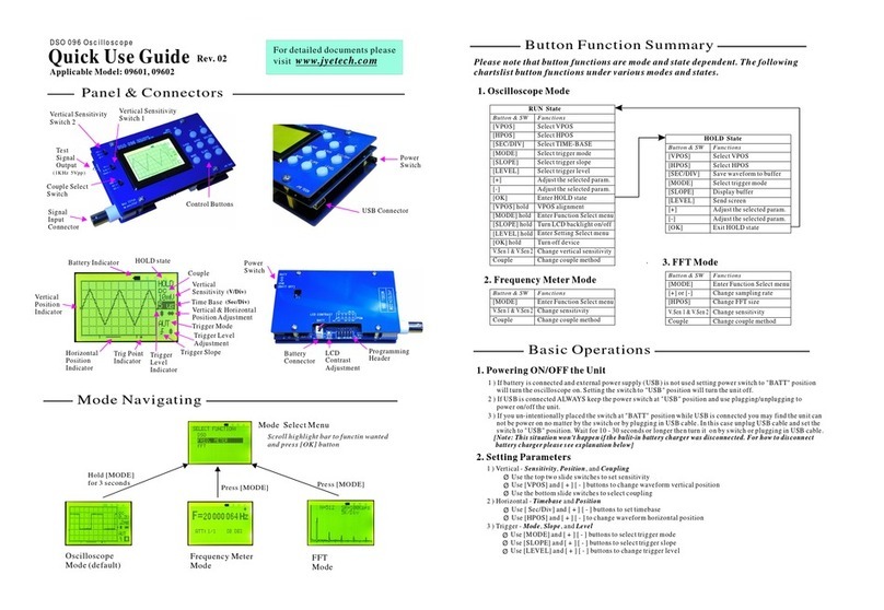
JYE Tech DSO 096 Operating manual

JYE Tech

JYE Tech DSO 096 Operating manual

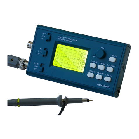
JYE Tech DSO 068 User manual

JYE Tech

JYE Tech DSO 068 User manual

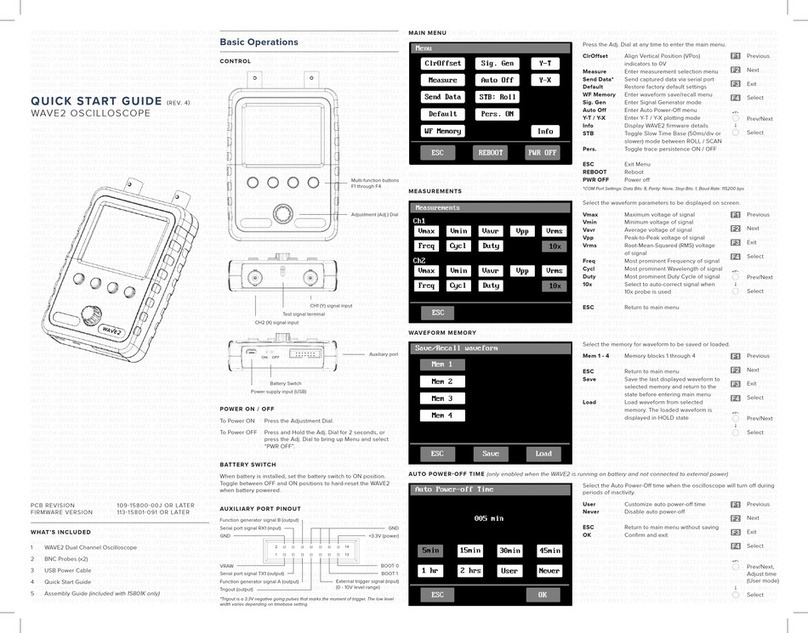
JYE Tech WAVE2 User manual

JYE Tech

JYE Tech WAVE2 User manual

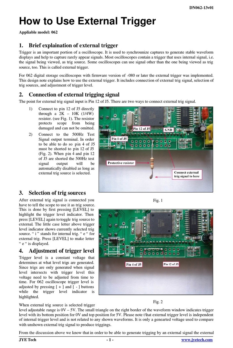
JYE Tech 062 Operating instructions

JYE Tech

JYE Tech 062 Operating instructions

JYE Tech 13803K User manual

JYE Tech

JYE Tech 13803K User manual

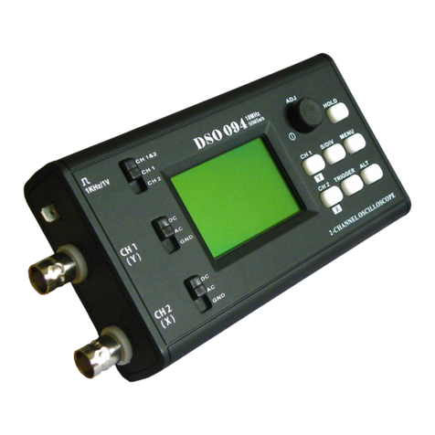
JYE Tech DSO 094 User manual

JYE Tech

JYE Tech DSO 094 User manual

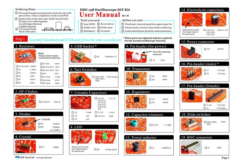
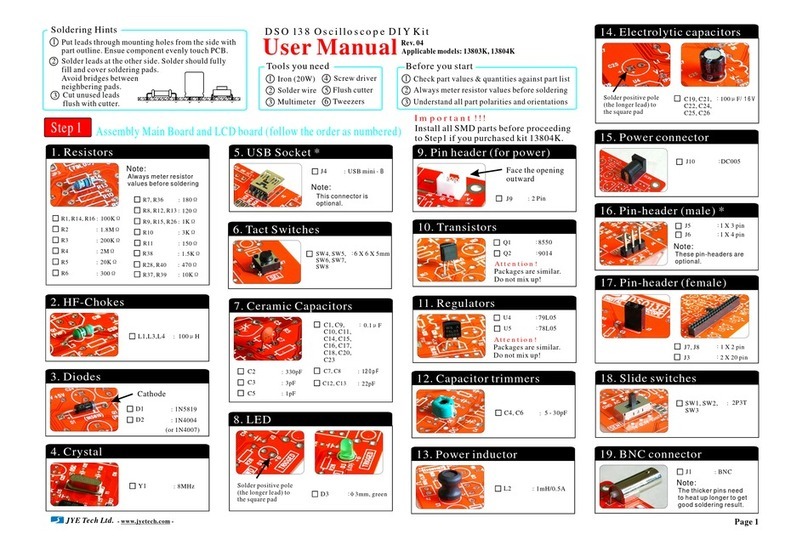
JYE Tech DSO 138 User manual

JYE Tech

JYE Tech DSO 138 User manual

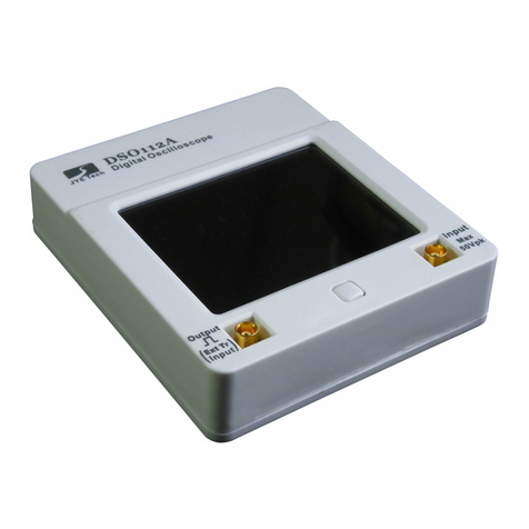
JYE Tech DSO112A User manual

JYE Tech

JYE Tech DSO112A User manual

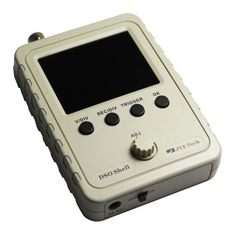
JYE Tech DSO Shell 150 User manual

JYE Tech

JYE Tech DSO Shell 150 User manual

JYE Tech DSO 138 User manual

JYE Tech

JYE Tech DSO 138 User manual

JYE Tech DSO 068 User manual

JYE Tech

JYE Tech DSO 068 User manual

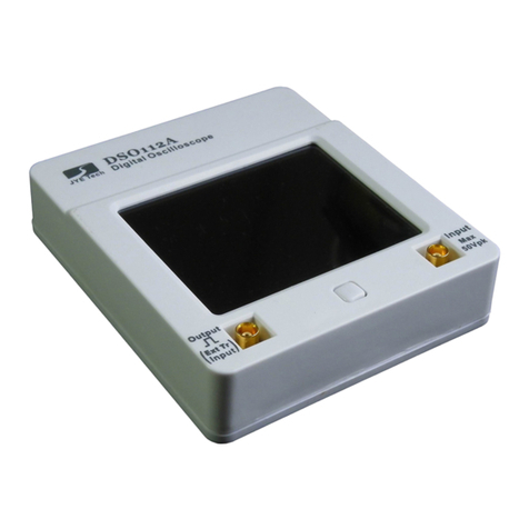
JYE Tech DSO112A User manual

JYE Tech

JYE Tech DSO112A User manual

JYE Tech 062 Quick start guide

JYE Tech

JYE Tech 062 Quick start guide

Popular Test Equipment manuals by other brands

Fluke i400 Calibration information

Fluke

Fluke i400 Calibration information

Walter SURFOX owner's manual

Walter

Walter SURFOX owner's manual

TiePie Handyprobe HP3 user manual

TiePie

TiePie Handyprobe HP3 user manual

Fluke TS54-A-09-TDR user guide

Fluke

Fluke TS54-A-09-TDR user guide

Wavecrest SIA-3000 manual

Wavecrest

Wavecrest SIA-3000 manual

PIE Evolution piecal 211 operating instructions

PIE

PIE Evolution piecal 211 operating instructions

Kett L-500 operating manual

Kett

Kett L-500 operating manual

Hydrajaws M35+ user manual

Hydrajaws

Hydrajaws M35+ user manual

Kewtech KT1795 instruction manual

Kewtech

Kewtech KT1795 instruction manual

Viavi RGS-2000NG Operation manual

Viavi

Viavi RGS-2000NG Operation manual

Tektronix 11801C user manual

Tektronix

Tektronix 11801C user manual

Clearaudio double matrix professional SONIC user manual

Clearaudio

Clearaudio double matrix professional SONIC user manual

WEBTEC DHCR 2 Series user manual

WEBTEC

WEBTEC DHCR 2 Series user manual

Gossen MetraWatt METRISO 1000A operating instructions

Gossen MetraWatt

Gossen MetraWatt METRISO 1000A operating instructions

SF AllVac Commercial Installation operation & maintenance

SF

SF AllVac Commercial Installation operation & maintenance

TriBrer TB-700 user manual

TriBrer

TriBrer TB-700 user manual

General tools FHT803 instruction manual

General tools

General tools FHT803 instruction manual

AFL WDM900 user guide

AFL

AFL WDM900 user guide

manuals.online logo
manuals.online logoBrands
  • About & Mission
  • Contact us
  • Privacy Policy
  • Terms and Conditions

Copyright 2025 Manuals.Online. All Rights Reserved.