KÜBLER SPORT OxyCycle 3 User manual

Service Manual

1
TABLE OF CONTENTS
HOW TO REMOVE THE CONTROLLER BRACKET -------------------------- 2
HOW TO REMOVE THE FOOT PEDALS ----------------------------------------- 3
HOW TO REMOVE THE CRANKS ------------------------------------------------- 3
HOW TO REMOVE THE COVERS ------------------------------------------------- 6
HOW TO REPLACE A NEW MOTOR ---------------------------------------------- 7
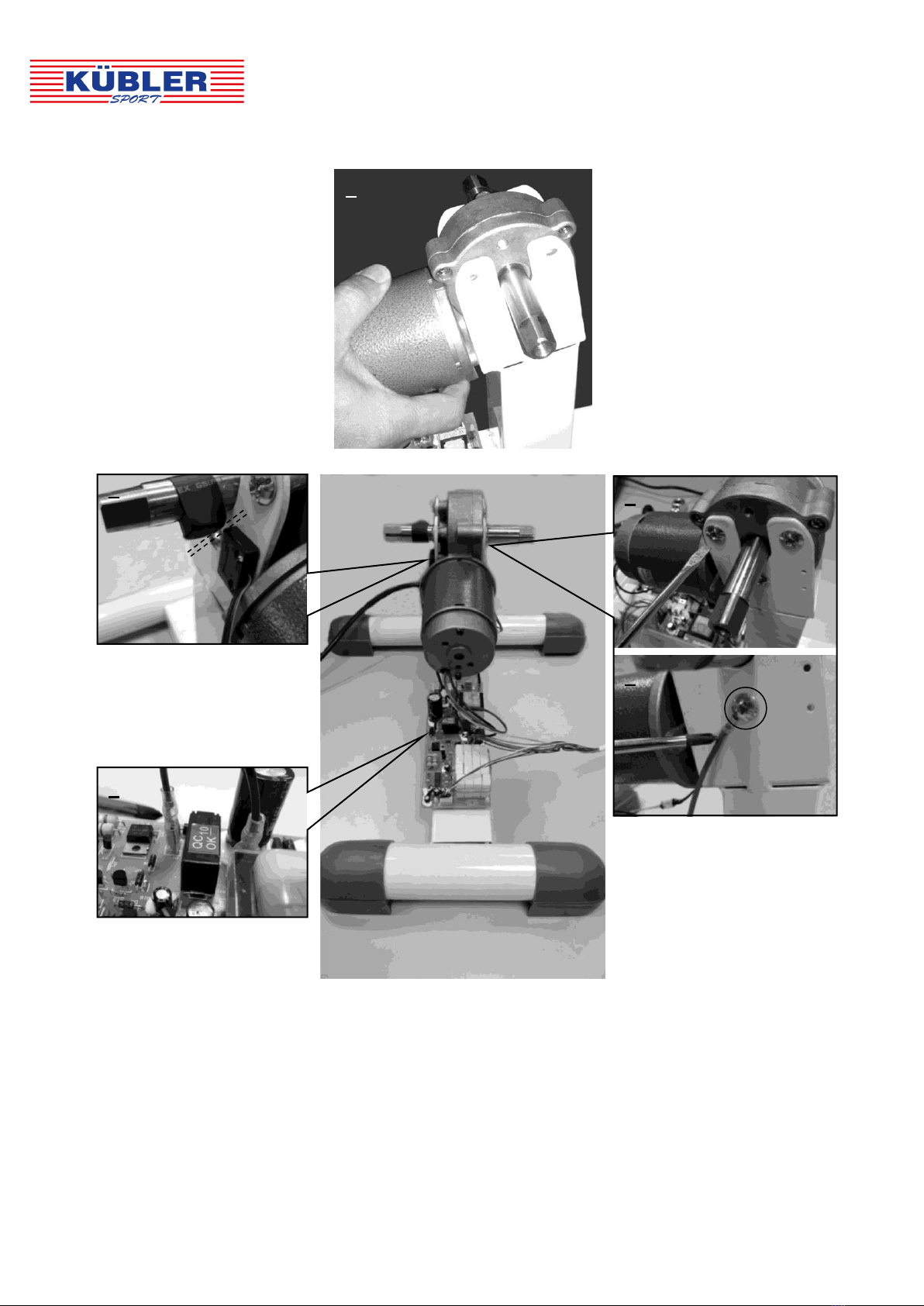
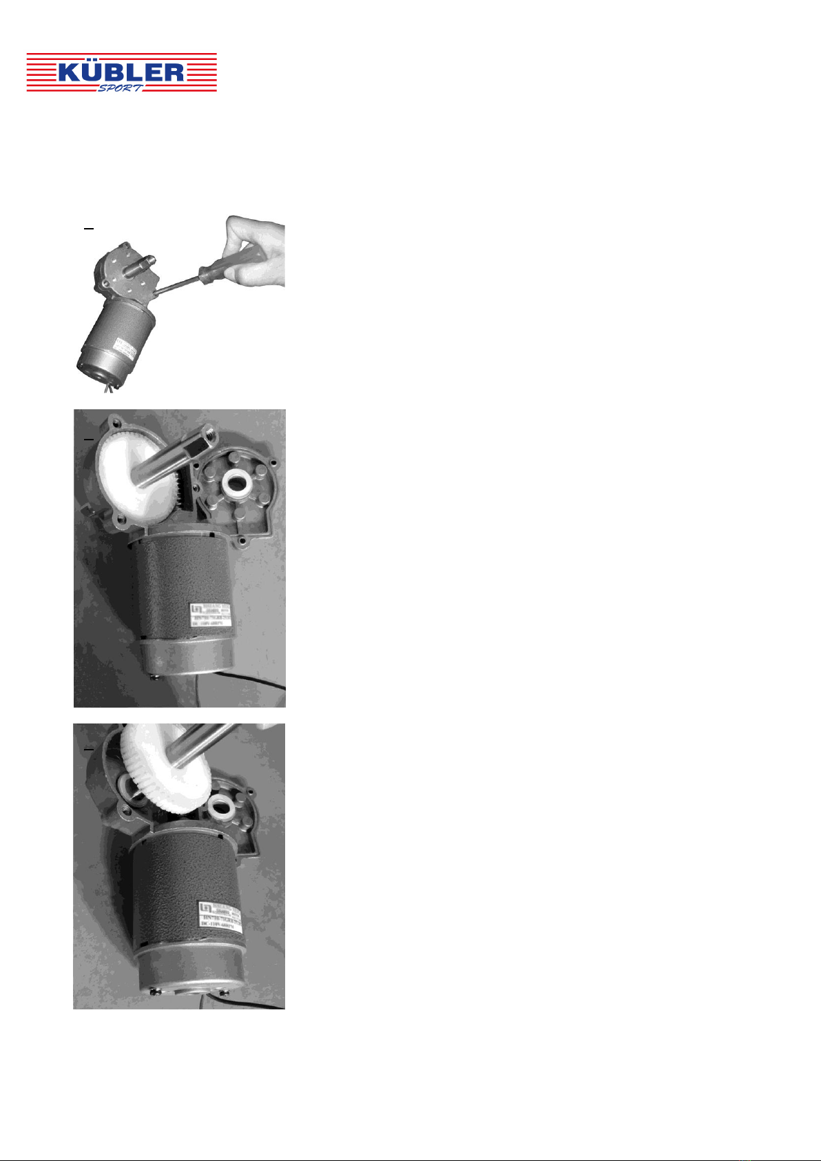
REMOVE THE MOTOR ----------------------------------------------------------- 7
REPLACE A NEW MOTOR ------------------------------------------------------ 8
HOW TO REPLACE THE ROTOR -------------------------------------------------- 9
REMOVE THE ROTOR ----------------------------------------------------------- 9
PLACE THE NEW ROTOR ------------------------------------------------------- 10
HOW TO REPLACE THE POWER CONTROL BOARD ----------------------- 12
REMOVE THE POWER CONTROL BOARD -------------------------------- 12
PLACE THE NEW POWER CONTROL BOARD --------------------------- 13
HOW TO REPLACE THE CONTROLLER ----------------------------------------- 14
REMOVE THE CONTROLLER --------------------------------------------------14
PLACE THE NEW CONTROLLER --------------------------------------------- 15
INSTALL THE COVERS BACK TO THE DEVICE --------------------------------16
INSTALL THE CRANKS BACK TO THE DEVICE ------------------------------- 17
INSTALL THE FOOT PEDALS BACK TO THE CRANKS ----------------------18
INSTALL THE CONTROLLER BRACKET BACK TO THE DEVICE ---------18
HOW TO USE YOUR OXYCYCLE III PEDAL EXERCISER ------------------ 20

2
HOW TO REMOVE THE CONTROLLER BRACKET
4
3
2
1
STEP 1
Remove the Controller from the Controller Bracket.
STEP 2
Remove the Bolt and Nut with a Screwdriver.
STEP 3
Remove the Bolt and Nut from the Controller Bracket.
STEP 4
Remove the Controller Bracket.

3
HOW TO REMOVE THE FOOT PEDALS
HOW TO REMOVE THE CRANKS
1
2
STEP 1
Remove both Right and Left Foot Pedals with a
Wrench.
NOTE: The Cranks and Foot Pedals are marked
“R” for Right and “L” for Left.
STEP 2
Turn the pedal shaft from the Right Foot Pedal by
wrench in the counter-clockwise direction until
loosen. Then remove the Right Foot Pedal.
Turn the pedal shaft from the Left Foot Pedal by
wrench in the clockwise direction until loosen.
Then remove the Left Foot Pedal.
2
STEP 1
Turn the Plastic Cap with Pliers in the
clockwise direction until loosen.
STEP 2
Remove the Plastic Cap on the Right Crank.
1

4
6
3
4
5
STEP 3
Remove the Bolt by using anAllen Wrench.
STEP 4
Remove the Bolt.
STEP 5
Remove the Right Crank by using a Crank Puller.
STEP 6
Turn the head from the Crank Puller in
clockwise direction into the Right Crank. Make
sure it is threaded all the way in.

5
7
8
STEP 7
Turn the Crank Puller arm in the clockwise direction
while holding onto the Right Crank.
STEP 8
Remove the Right Crank.
NOTE: Repeat STEP 1 to STEP 8 for removing the
Left Crank.

6
HOW TO REMOVE THE COVERS
STEP 1
Remove the Right Cover which is held on by
nine Bolts. Remove the bolts with a Screwdriver.
STEP 2
Remove the Left Cover which is held on by two
Bolts. Remove the bolts with a Screwdriver.
STEP 3
Remove the Right Cover.
STEP 4
The Left and Right Covers are removed.
3
4
2
1
1
2

7
HOW TO REPLACE THE MOTOR
REMOVE THE MOTOR
1
2
3
STEP 1
Remove the Red wire from the
PCB (Power Control Board) by
simply pulling it off with Pliers.
STEP 2
Remove the Black wire from
the PCB (Power Control
Board) by simply pulling it
off with Pliers.
STEP 3
Remove six Bolts from
Main Frame by using
a Screwdriver.
Tool Required:
Pliers
STEP 4
Remove the Motor
from the Main Frame.
4

8
PLACE THE NEW MOTOR
4
STEPS 2 and 3Place
the new motor onto
the Main Frame with
six Bolts that were
removed.
Be careful: the Bolt
under the motor axle
must be attached with
the wire onto the Main
Frame.
STEP 5
There is a gap
between the
magnet and the
sensor.
STEP 4
Reconnect both Red
and Black wires in
their respective plugs
on the PCB (Power
Control Board).
5
STEP 1
Place the new Motor
onto the Main Frame.
1
2
3

9
HOW TO REPLACE THE ROTOR
REMOVE THE ROTOR
1
2
3
STEP 1
Remove the cover which is held on by three Bolts.
Remove the bolts with a Screwdriver.
STEP 2
Remove the cover from the Motor.
STEP 3
Remove the Rotor.

10
PLACE THE NEW ROTOR
2
2-1
4
5
STEPS 4
The Rotor with Flying
Wheel is removed.
NOTE: There is only
one Plastic Washer
on the motor side.
STEPS 5
NOTE: There are three
Plastic Washers on the
cover side.
STEP 1
Place the new Rotor into the housing.
1
NOTE: There is only
one Plastic Washer
on the motor side.
NOTE: There are
three Plastic
Washers on the
cover side.

11
STEP 2
Place three Plastic Washers onto the axle of the rotor
and then install the cover back to the motor.
2
3
STEP 3
Attach the cover onto the motor with the three Bolts
that were removed. Tighten the bolts with a
Screwdriver.
NOTE: There are
three Plastic
Washers on the
cover side.

12
HOW TO REPLACE THE NEW POWER CONTROL
BOARD
REMOVE THE POWER CONTROL BOARD
Tool Required:
Pliers
1
2
1
2
3
4
5
6
STEPS 1 and 2
Pinch the head of the
support by using the
Pliers, then pull the
PCB out.
There are six PCB (Power Control Board) Supports to fix
the PCB in place.

13
PLACE THE NEW POWER CONTROL BOARD
1
2
3
STEP 1
There are six PCB (Power
Control Board) Supports on
the Main Frame.
STEP 2
Position the PCB (Power
Control Board) on the Main
Frame and align the
support holes.
STEP 3
Snap-inthe PCB (Power
Control Board) to fix it in
place.

14
HOW TO REPLACE THE CONTROLLER
REMOVE THE CONTROLLER
STEP 3
Remove the cable
connector from the PCB
by pulling it off carefully.
STEP 2
Remove the
cable connector
from the PCB by
pulling it off
carefully.
STEP 1
Disconnect both wires.
3
2
1

15
PLACE THE NEW CONTROLLER
STEP 3
Reconnect the cable
connector in its plug on
the PCB.
STEP 2
Reconnect the
cable connector
in its plug on the
PCB.
STEP 1
Reconnect the wire
from the Controller to
the wire from the
Sensor.
3
2
1

16
INSTALL THE COVERS BACK TO THE DEVICE
1
STEP 2
Attach the Left and Right Covers with the nine Bolts
that were removed at the Right side. Tighten the
bolts with a Screwdriver.
STEP 1
Install both Left and Right Covers back to the device.
2
3
1
2
STEP 3
Attach the Left and Right Covers with the two Bolts
that were removed at the Left side. Tighten the
bolts with a Screwdriver.

17
INSTALL THE CRANKS BACK TO THE DEVICE
4
1
2
3
STEP 4
Install the Plastic Cap back onto the Right Crank that
was removed.
STEP 3
Tighten the bolt with an Allen Wrench.
STEP 2
Attach the Right Crank with the Bolt that was
removed. Tighten the bolts with a
Screwdriver.
STEP 1
Install the Right Crank back to the motor axle.
NOTE: The Cranks are marked “R” for Right and
“L” for Left.
5
STEP 5
Tighten the Plastic Cap with Pliers in the
counter-clockwise direction.
NOTE: Repeat STEP 1 to STEP 5 for installing the
Left Crank.

18
INSTALL THE FOOT PEDALS BACK TO THE
CRANKS
INSTALL THE CONTROLLER BRACKET BACK TO
THE DEVICE
2
1
STEPS 1 and 2
The Foot Pedals are marked “R” for Right and
“L” for Left.
For Right Foot Pedal:
Insert the pedal shaft from the Right Foot Pedal
into the threaded hole in Right Crank. Turn the
pedal shaft by hand in clockwise direction and it
with a Wrench.
For Left Foot Pedal:
Insert the pedal shaft from the Left Foot Pedal into
the threaded hole in Left Crank. Turn the pedal
shaft by hand in counter-clockwise direction and it
with a Wrench.
1
STEP 1
Install the Controller Bracket back onto the covers.

19
2
3
4
STEP 2
Attach the Controller Bracket onto the Covers with a
Bolt and Nut.
STEP 3
Tighten the bolt with a Screwdriver.
STEP 4
Slide the Controller back onto the Controller Bracket.
This manual suits for next models
1
Table of contents
Other KÜBLER SPORT Fitness Equipment manuals
Popular Fitness Equipment manuals by other brands

Kayakpro
Kayakpro SUP ERGO Assembly & instruction manual

NordicTrack
NordicTrack Nordic Fitness Chair Assembly, operating and training program

Keiser
Keiser m5 quick start guide

Sportplus
Sportplus SP-LB-1000-R-iE user manual

Apollo
Apollo 7000 Series owner's manual

Next Level Racing
Next Level Racing FLIGHT SIMULATOR NLR-S018 instruction manual