manuals.online logo
Brands
  1. Home
  2. •
  3. Brands
  4. •
  5. K-Rain
  6. •
  7. Irrigation System
  8. •
  9. K-Rain R-200 User manual

K-Rain R-200 User manual

K-RAIN MANUFACTURING CORP.
1640 Australian Avenue
Riviera Beach, FL 33404
(561) 844-1002 | 1.800.735.7246 | www.krain.com
K-RAIN MANUFACTURING CORP.
1640 Australian Avenue
Riviera Beach, FL 33404
(561) 844-1002 | 1.800.735.7246 | www.krain.com
BYPASSING THE SENSOR
Should you desire to bypass the operation of the rain sensor for any reason (i.e.,turn on your system even
though the rain sensor has shut “off” due to rainfall), there is an easy way to do this. Simply go to the rain sensor
and raise the rain quantity “cap” setting higher, or completely remove it altogether. This takes the pressure off
the switch button, which allows the valve circuit to close again.
Note: Using the Manual switch on the controller may not bypass the sensor.
MAINTENANCE
There is no required maintenance for the unit. The rain sensor does not have to be removed or covered
for winterizing purposes.
TROUBLESHOOTING
Follow these simple checks before replacing your rain sensor:
System will not come on at all:
A. Check to see that the rain sensor discs are dry and switch “clicks” on and off freely by pressing the top of
the spindle.
B. Look for breaks in the wire leading to the rain sensor and check all wire junctions.
C. If the rain sensor is dry and the wire leading to it is good, check the rain sensor switch by nicking the
insulation of the two “outer” wires near the unit to expose copper. Turn one sprinkler zone on, and apply
a “jumper wire” across the two exposed wires. If the sprinkler now comes on, the switch is bad. Wrap all
nicked wires with electrical tape.
D. The rain sensor is wired to function with most controllers (normally closed). If you are unable to make the
sensor work with the suggestion above you may have a unique controller (normally open).
System will not shut off even after heavy rainfall:
A. Check wiring for correct installation (See “Adjustments and Operation” section).
B. Check sensitivity setting on rain sensor, and move the cap to a more sensitive setting. The rain sensor is
an accurate rain gauge and can be verified by setting up a “tube” type rain gauge in the same vicinity and
making periodic readings.
C. Check for obstructions to rainfall such as overhangs, trees or walls.
WARRANTY
K-Rain Manufacturing warrants that its products will be free from materials and workmanship defects for a
period of 2 years. With proof of purchase provided, K-Rain will replace, free of charge, the defective part or
parts found to be defective under normal use and service for the warranty period. Prior to replacement, K-Rain
reserves the right to inspect and authorize the defective part or parts; all defectives must be authorized in
writing by K-Rain. Liability under this warranty is limited solely to the replacement or repair of defective parts.
This warranty is given expressly and in place of all other expressed or implied warranties including but not
limited to warranties regarding fitness for use of merchantability. No agent or representative has authority to
waive or alter this warranty.
© K-Rain Manufacturing Corporation Made in China
AN ISO 9001:2008 CERTIFIED COMPANY R2005101 Rev10
INTRODUCTION
Thank you for selecting a K-Rain R-200 RainSensor. This sensor will provide conservation, convenience, and
flexibility to your fully automatic watering system. Never again will you see your sprinklers running on a rainy
day. Now, after a set amount of rain has fallen, the sensor engages a switch that will prevent the controller from
watering. Once the rain sensor has dried sufficiently, the sensor allows normal sprinkler operation.
RAIN SENSOR
INSTALLATION
MANUAL
RAIN SENSOR
INSTALLATION
MANUAL
R-200
Gutter & Surface Mount
Rain Sensor
R-200 Gutter & Surface Mount Rain Sensor
INSTALLATION INSTRUCTIONS
MOUNTING
The R-200 sensor includes 2 mounting options:
1. Rain Gutter
2. Flat Surface
Mount the rain sensor where it will be exposed to direct, unobstructed rainfall (but away from sprinkler spray).
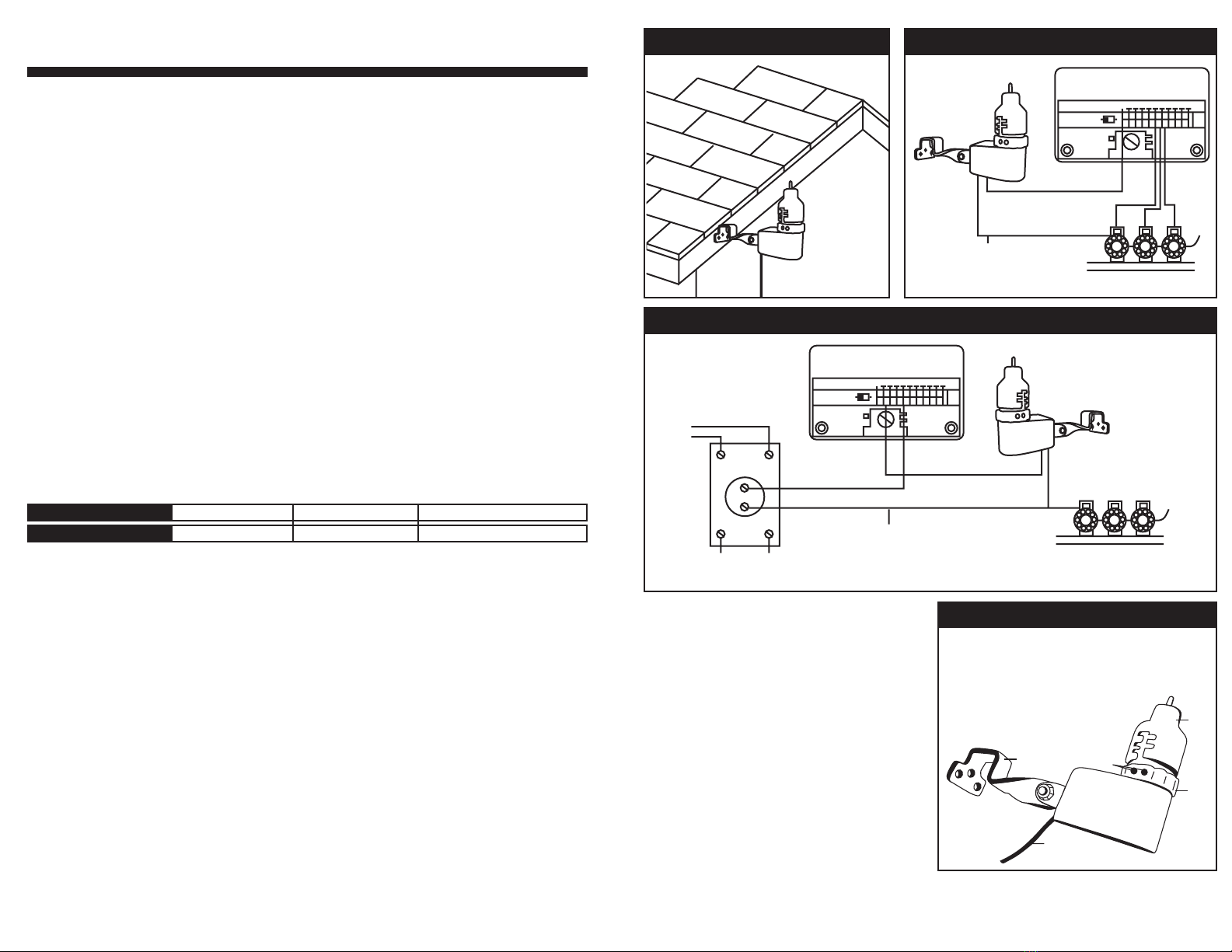
The Switch-housing portion must be upright (See Figure 1).
Hints for mounting:
A. Mount as close as possible to the timer. This will cause the wire run to be shorter, which minimizes the
possibility of wire breaks.
B. Mount in the highest possible position where rain can fall directly upon the rain sensor.
C. As described in the “Adjustments and Operation” section of the manual, “reset rate” refers to the amount of
time it takes the rain sensor to dry out sufficiently for the sprinkler system to be allowed to come back on.
The mounting location will affect this rate and should be taken into consideration should extreme conditions
exist. For example, mounting the rain sensor on a very sunny, southeastern end of a building may cause
the rain sensor to dry out sooner than desired. Similarly, mounting on the northern end of a building with
constant shade may keep the rain sensor from drying soon enough. Some experimentation and use of the
“vent ring” (as described later) will usually yield satisfactory results.
Once the rain sensor is mounted, run the wire to the controller, using wire clips every few feet to fasten it. If an
extension to the wire provided is needed, use the following table to determine the minimum wire gauge needed:
WIRING
IMPORTANT: The rain sensor is sold and designed for 24-VAC irrigation controllers only. All wiring must
conform to applicable local codes. The two most common wiring situations are detailed below for controllers
that do not have direct rain sensor & pump start relay wiring capabilities. For non-standard wiring situations,
please consult your distributor.
A. 24-VAC Solenoid Valves Only (No Pump Start Relay See Figure 2) With the two wires from the rain sensor
at the controller, locate the “common ground” wire of the solenoid valves. If it is connected to the common
terminal on the controller disconnect it. Attach one wire of the rain sensor to the “common” terminal
(usually marked “COM”) on the controller. Attach the other wire of the rain sensor to the common wire
leading to the valves. Note: The common wire to the valves does not have to be interrupted at the
controller.The rain sensor may be wired anywhere along the common wire line.
B. 24-VAC Solenoid Valves with Pump Start Relay (See Figure 3). Locate the common wire to the solenoid
valves and the common wire lead to the coil of the relay that starts the pump. If these two wires are
connected to the “common” terminal on the controller, disconnect both of them. Twist these two wires
together along with one wire from the rain sensor and secure with a wire nut. Attach the other wire of the
rain sensor to the “common” terminal on the controller.
CHECK TO VERIFY CORRECT WIRING
Turn on one zone of the sprinkler system that is visible while you are in reach of the rain sensor. Manually
depress the spindle at the top of the rain sensor until you hear the switch “click” off. The sprinkler zone should
stop instantly. If it does not, check wiring for correct installation.
ADJUSTMENTS AND OPERATION
The rain sensor can keep the irrigation system from
starting or continuing after rainfall quantities of 1/8”,
¼”, ½”, ¾”, or 1”. To adjust it to the desired quantity of
rainfall, rotate the cap on the switch housing so that
the pins are located in the proper slots (See Figure 4).
Do not forcibly twist the cap as this might break the pins.
The time that it takes the rain sensor to reset for normal
sprinkler operation after the rain has stopped is determined
by weather conditions (wind, sunlight, humidity, etc.).
These conditions will determine how fast the hygroscopic
discs will dry out, and since the landscape will also be
experiencing the same conditions, the irrespective drying
rates will roughly parallel each other. Note that there is
an adjustment capability on the rain sensor that will slow
down the reset rate. By turning the “ventring” (See Figure
4) to completely or partially cover the ventilation holes, the hygroscopic discs will dry more slowly. This adjustment
can compensate for an “overly sunny” installation location or peculiar soil conditions. Experimenting with the vent
ring will best determine the ideal vent setting.
Extension needed:
then use:
25-50 ft.
20 AWG
50-100 ft.
18 AWG
100 ft. or more
16 AWG
A
B
C
D
E
F
A Cap
B Vent Ring
C Ventalation Holes
D Housing
E Mounting Bracket
F 24 VAC Wire to Controller
FIGURE 1: Mounting Rain Sensor
FIGURE 3: Wiring
FIGURE 2: Wiring
FIGURE 4: Parts Diagram
Timer - Controller
Line-In
Common Wire
to All Valves
Line-Out
(on Pump)
Pump
Start
Relay
Solenoid Valves
Rain Sensor
Timer - Controller
Common Wire
to All Valves
Solenoid Valves
Rain Sensor
Timer - Controller
Line-In
Common Wire
to All Valves
Line-Out
(on Pump)
Pump
Start
Relay
Solenoid Valves
Rain Sensor
Timer - Controller
Common Wire
to All Valves
Solenoid Valves
Rain Sensor
Timer - Controller
Line-In
Common Wire
to All Valves
Line-Out
(on Pump)
Pump
Start
Relay
Solenoid Valves
Rain Sensor
Timer - Controller
Common Wire
to All Valves
Solenoid Valves
Rain Sensor

Other K-Rain Irrigation System manuals

K-Rain RPS Series Operating manual

K-Rain

K-Rain RPS Series Operating manual

K-Rain ProSport 14003 Operating manual

K-Rain

K-Rain ProSport 14003 Operating manual

K-Rain RPS50 Operating manual

K-Rain

K-Rain RPS50 Operating manual

K-Rain ProPlus Operating manual

K-Rain

K-Rain ProPlus Operating manual

K-Rain KRX6 User manual

K-Rain

K-Rain KRX6 User manual

K-Rain PRO-LC User manual

K-Rain

K-Rain PRO-LC User manual

K-Rain SMARTSET K2 Operating manual

K-Rain

K-Rain SMARTSET K2 Operating manual

K-Rain RPS50 Operating manual

K-Rain

K-Rain RPS50 Operating manual

K-Rain KRC 9 User manual

K-Rain

K-Rain KRC 9 User manual

K-Rain RPS 46 User manual

K-Rain

K-Rain RPS 46 User manual

K-Rain Sure Throw ST-IS45 User manual

K-Rain

K-Rain Sure Throw ST-IS45 User manual

K-Rain MiniPro Operating manual

K-Rain

K-Rain MiniPro Operating manual

K-Rain RPS75 Operating manual

K-Rain

K-Rain RPS75 Operating manual

K-Rain RPS 75 Operating manual

K-Rain

K-Rain RPS 75 Operating manual

K-Rain RPS Select Operating manual

K-Rain

K-Rain RPS Select Operating manual

K-Rain K2 SMARTSET Operating manual

K-Rain

K-Rain K2 SMARTSET Operating manual

K-Rain K2Pro Operating manual

K-Rain

K-Rain K2Pro Operating manual

K-Rain K2Pro Operating manual

K-Rain

K-Rain K2Pro Operating manual

K-Rain RPS 46 User manual

K-Rain

K-Rain RPS 46 User manual

K-Rain ProCom Operating manual

K-Rain

K-Rain ProCom Operating manual

K-Rain RPS 75i Operating manual

K-Rain

K-Rain RPS 75i Operating manual

K-Rain SuperPro with Intelligent Flow Technology Operating manual

K-Rain

K-Rain SuperPro with Intelligent Flow Technology Operating manual

Popular Irrigation System manuals by other brands

Globe GL-RES/DC Series manual

Globe

Globe GL-RES/DC Series manual

Viking MicrofastHP VK344 Technical data

Viking

Viking MicrofastHP VK344 Technical data

Eden 94124EDAMZ quick start guide

Eden

Eden 94124EDAMZ quick start guide

Eden 94152EDAMZ quick start guide

Eden

Eden 94152EDAMZ quick start guide

Rain Bird LNDDRIPKIT installation instructions

Rain Bird

Rain Bird LNDDRIPKIT installation instructions

Hunter I-80 installation instructions

Hunter

Hunter I-80 installation instructions

Reliable F1-56-300 Series manual

Reliable

Reliable F1-56-300 Series manual

Toro 570Z PRX Series Specifications

Toro

Toro 570Z PRX Series Specifications

Autopot 12Pot System Set-up guidelines

Autopot

Autopot 12Pot System Set-up guidelines

Tyco Fire Product Gem DS-1 instruction manual

Tyco Fire Product

Tyco Fire Product Gem DS-1 instruction manual

Senju Sprinkler RC-QR manual

Senju Sprinkler

Senju Sprinkler RC-QR manual

Tyco TY5332 quick start guide

Tyco

Tyco TY5332 quick start guide

Hunter ST Series owner's manual

Hunter

Hunter ST Series owner's manual

Fiskars 1023656 Original instructions

Fiskars

Fiskars 1023656 Original instructions

Tyco LFII Series quick start guide

Tyco

Tyco LFII Series quick start guide

Tyco CC2 quick start guide

Tyco

Tyco CC2 quick start guide

Gardena OS 140 operating instructions

Gardena

Gardena OS 140 operating instructions

claber Aqua-Magic System user manual

claber

claber Aqua-Magic System user manual

manuals.online logo
manuals.online logoBrands
  • About & Mission
  • Contact us
  • Privacy Policy
  • Terms and Conditions

Copyright 2025 Manuals.Online. All Rights Reserved.