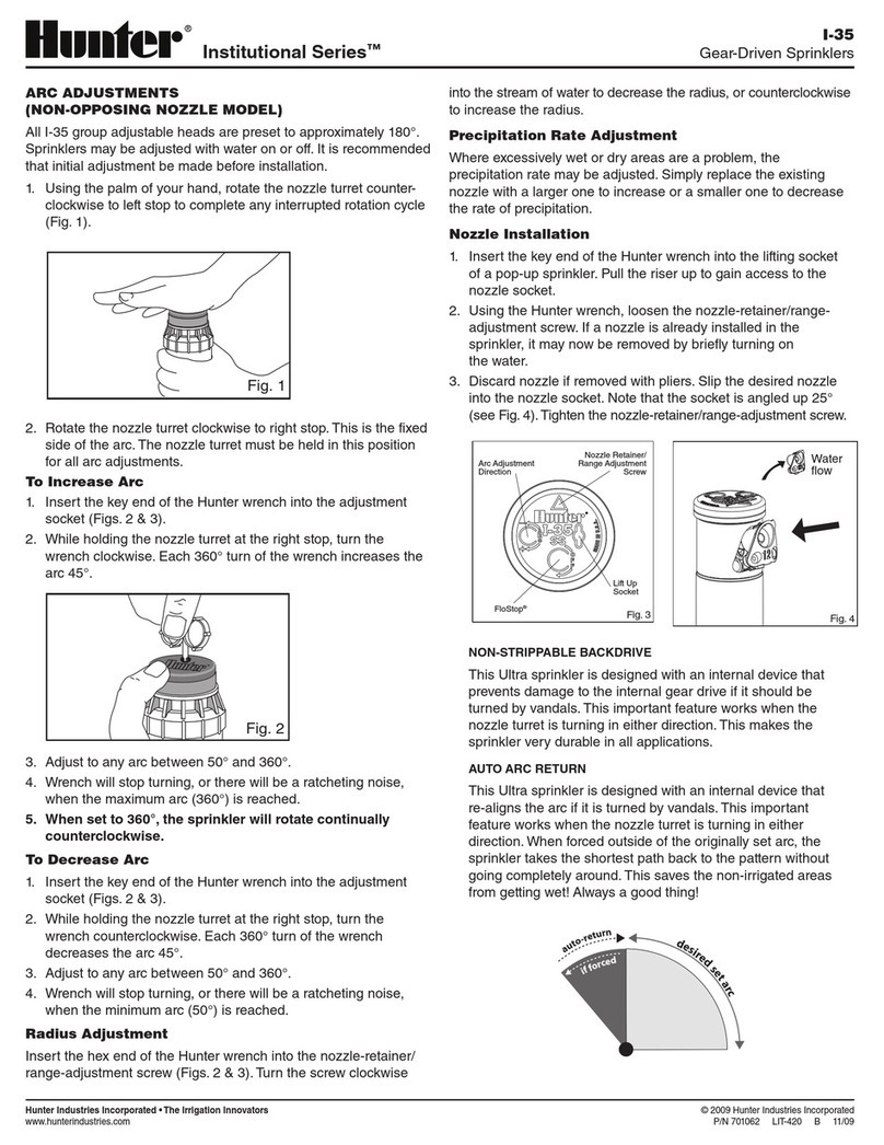
RC-099 -EM A 2/19
I80ON NOZZLE PERFORMANCE DATA*
Nozzle Set Pressure Radius
m
Flow Precip mm/hr
bar kPa m3/hr l/min
3.4 344 14.9 3.23 53.8 14.5 16.7
Tan Grey 4.1 413 15.5 3.57 59.4 14.8 17.0
15 4.5 450 15.9 3.73 62.1 14.8 17.1
4.8 482 16.2 3.86 64.4 14.8 17.1
803611 White 315317 5.5 551 16.8 4.13 68.9 14.7 17.0
3.4 344 17.1 3.91 65.1 13.4 15.5
Tan Grey 4.1 413 17.7 4.28 71.3 13.7 15.8
18 4.5 450 18.0 4.48 74.6 13.8 16.0
4.8 482 18.3 4.54 75.7 13.6 15.7
803611 Orange 315317 5.5 551 18.6 4.82 80.3 13.9 16.1
3.4 344 17.4 4.18 69.7 13.8 16.0
Tan Grey 4.1 413 18.0 4.61 76.8 14.3 16.5
20 4.5 450 18.6 4.86 81.0 14.1 16.2
4.8 482 19.2 4.91 81.8 13.3 15.4
803611 Brown 315317 5.5 551 19.5 5.16 85.9 13.5 15.6
3.4 344 19.2 4.91 81.8 13.3 15.4
Tan Lt. Blue 4.1 413 19.8 5.22 87.1 13.3 15.4
23 4.5 450 20.1 5.45 90.8 13.5 15.6
4.8 482 20.4 5.66 94.3 13.6 15.7
803611 Green 315311 5.5 551 20.7 6.04 100.7 14.1 16.2
4.5 450 21.6 6.50 108.3 13.9 16.0
Tan Lt. Blue 4.8 482 22.3 6.75 112.5 13.6 15.7
25 5.5 551 22.6 7.19 119.8 14.1 16.3
6.2 620 22.9 7.65 127.5 14.6 16.9
803611 Blue 315311 6.9 689 23.5 8.12 135.3 14.7 17.0
4.5 450 22.6 7.02 117.0 13.8 15.9
Tan Lt. Blue 4.8 482 22.9 7.27 121.1 13.9 16.1
33 5.5 551 23.5 7.77 129.5 14.1 16.3
6.2 620 24.1 8.22 137.0 14.2 16.4
803611 Grey 315311 6.9 689 24.7 8.68 144.6 14.2 16.4
4.5 450 23.5 7.97 132.9 14.5 16.7
Tan Lt. Blue 4.8 482 24.1 8.31 138.5 14.3 16.6
38 5.5 551 25.0 8.84 147.3 14.1 16.3
6.2 620 25.6 9.38 156.3 14.3 16.5
803611 Red 315311 6.9 689 26.5 9.90 165.0 14.1 16.3
-------
Tan Blue 4.8 482 25.3 9.38 156.3 14.7 16.9
43 5.5 551 25.9 9.90 165.0 14.8 17.0
6.2 620 26.5 10.52 175.3 15.0 17.3
803611 Dk. Brown 315300 6.9 689 27.1 11.09 184.7 15.1 17.4
-------
Dk. Brown Dk. Blue 4.8 482 27.4 10.65 177.5 14.2 16.3
48 5.5 551 28.0 11.11 185.1 14.1 16.3
6.2 620 28.7 11.46 191.0 14.0 16.1
803610 Dk. Green 833500 6.9 689 29.3 12.15 202.5 14.2 16.4
-------
Dk. Brown Dk. Blue 4.8 482 27.7 11.31 188.5 14.7 17.0
53 5.5 551 28.3 11.86 197.7 14.8 17.0
6.2 620 29.0 12.61 210.1 15.0 17.4
803610 Dk. Blue 833500 6.9 689 29.6 13.29 221.4 15.2 17.6
LOWANGLE NOZZLES**
I80 NOZZLESI80ON NOZZLES
I80 NOZZLE PERFORMANCE DATA
Nozzle Set Pressure Radius
m
Flow Precip mm/hr
bar kPa m3/hr l/min
Orange Dk. Green 3.4 344 11.3 2.02 33.7 15.9 18.4
4.1 413 11.9 2.23 37.1 15.8 18.2
10 4.5 450 12.5 2.32 38.6 14.8 17.1
803603 315312 - - - - - - -
Lt. Green - - - - - - -
Orange White 3.4 344 14.3 2.59 43.2 12.6 14.6
4.1 413 14.6 2.79 46.6 13.1 15.1
13 4.5 450 14.9 2.93 48.8 13.1 15.2
803603 315314 - - - - - - -
Lt. Blue - - - - - - -
Orange White 3.4 344 15.9 2.93 48.8 11.7 13.5
4.1 413 15.9 3.29 54.9 13.1 15.1
15 4.5 450 16.2 3.38 56.4 13.0 15.0
803603 315314 4.8 482 16.2 3.52 58.7 13.5 15.6
White 5.5 551 16.5 3.75 62.5 13.8 16.0
Orange Lt. Green 3.4 344 17.4 3.77 62.8 12.5 14.4
4.1 413 17.7 4.04 67.4 12.9 14.9
18 4.5 450 18.0 4.23 70.4 13.1 15.1
803603 315313 4.8 482 18.3 4.41 73.4 13.2 15.2
Orange 5.5 551 18.6 4.66 77.6 13.5 15.6
Orange Lt. Green 3.4 344 18.0 4.07 67.8 12.6 14.5
4.1 413 18.6 4.43 73.8 12.8 14.8
20 4.5 450 18.9 4.50 75.0 12.6 14.5
803603 315313 4.8 482 19.2 4.68 78.0 12.7 14.7
Tan 5.5 551 19.5 5.02 83.7 13.2 15.2
Orange Lt. Green 3.4 344 19.8 4.59 76.5 11.7 13.5
4.1 413 20.1 5.02 83.7 12.4 14.3
23 4.5 450 20.4 5.43 90.5 13.0 15.0
803603 315313 4.8 482 20.4 5.50 91.6 13.2 15.2
Green 5.5 551 21.0 5.88 98.0 13.3 15.4
Red Green 4.5 450 21.6 6.43 107.1 13.7 15.8
4.8 482 21.9 6.66 110.9 13.8 16.0
25 5.5 551 22.3 7.16 119.2 14.5 16.7
803602 315310 6.2 620 22.6 7.59 126.4 14.9 17.2
Blue 6.9 689 22.9 8.04 134.0 15.4 17.8
Red
Green 4.5 450 21.9 6.95 115.8 14.4 16.7
4.8 482 22.3 7.18 119.6 14.5 16.7
33 5.5 551 22.9 7.70 128.3 14.7 17.0
803602 315310 6.2 620 23.5 8.13 135.5 14.8 17.0
Grey 6.9 689 24.1 8.61 143.5 14.8 17.1
Red Green 4.5 450 23.2 7.93 132.1 14.8 17.1
4.8 482 23.8 8.22 137.0 14.5 16.8
38 5.5 551 24.4 8.88 148.0 14.9 17.2
803602 315310 6.2 620 25.0 9.36 156.0 15.0 17.3
Red 6.9 689 25.6 9.88 164.7 15.1 17.4
Red Green - - - - - - -
4.8 482 24.7 9.36 156.0 15.4 17.7
43 5.5 551 25.3 9.88 164.7 15.4 17.8
803602 315310 6.2 620 26.2 10.49 174.9 15.3 17.6
Dk. Brown 6.9 689 27.1 11.06 184.3 15.0 17.4
Dk. Red Dk. Green - - - - - - -
4.8 482 25.3 10.52 175.3 16.4 19.0
48 5.5 551 25.9 10.99 183.2 16.4 18.9
803601 315312 6.2 620 27.1 11.74 195.7 16.0 18.4
Dk. Green 6.9 689 27.7 12.38 206.3 16.1 18.6
Dk. Red Dk. Green - - - - - - -
4.8 482 26.5 11.52 191.9 16.4 18.9
53 5.5 551 27.1 12.06 201.0 16.4 18.9
803601 315312 6.2 620 28.0 12.81 213.5 16.3 18.8
Dk. Blue 6.9 689 28.7 13.54 225.6 16.5 19.0
= Indicates installed nozzle plug P/N 315300
* Complies with ASAE standard. All precipitation rates calculated for 360°
operation. All triangular rates are equilateral.
**Low-angle nozzles reduce radius by 15%.
© 2019 Hunter Industries Inc. Hunter and the Hunter logo are trademarks of Hunter Industries, registered in the U.S. and other countries.
Use the pop-up riser removal instructions below to complete
riser removal and installation.
➊To install the turf cup to the top of the riser, the cup must
be correctly aligned with the top of the riser assembly.
②Locate the protruding vertical indicator on the outside of
the turf cup’s vertical surface near the top (Figure 17).
➌While holding the turf cup over the riser assembly, orient
the turf cup’s indicator mark to the riser’s nozzle retaining
screw.
④While maintaining this orientation, place the turf cup onto
the top of the riser. Then turn quickly clockwise to lock the
cup to the riser.
➊Pull the turf cup upward using at-nosed
pliers. Hold the riser assembly in the
popped-up position.
②Slide the adjustment wrench PN
991300SP onto the grey or black
adjustment ring below the nozzle turret.
Then release the cup downward (Figure 12
and Figure 13).
➌Hold the turret with the tool in one hand and
the riser and turf cup in the other. Remove the
cup with a quick counterclockwise turn and li
away (Figure 14).
④Use the Hunter wrench or T-handle tool PN
319100SP to engage the pull-up socket in
riser’s retainer cap (Figure 15).
➎Li the riser assembly slightly while removing
the adjustment wrench PN 991300SP. Then
lower the riser assembly into position
(Figure 16).
Figure 12
Figure 13
Figure 14 Figure 15 Figure 16 Figure 17
