K-Systems G210 InviCell User manual

Document K32903 | Issue: 9 | Date: June 4, 2018 | DRF: 4602
0086
User Manual
Models: InviCell Standard and InviCell Plus
G210 InviCell
CO2/O2 Incubator

Contents
Section 1 - Preface 5
Section 2 - Safety 6
Safety and Reliability 6
Warnings 6
Cautions 6
Symbols 8
Section 3 - Installation 10
Before Installation 10
Placement 10
Section 4 - Intended Use 11
Applicable Part Numbers 11
Significant Performance Characteristics 11
Operation Principle 11
User Profile 11
Operating Environment 11
Dish Inserts 12
Chamber Heating 12
Chamber Lid 12
Preparation Chamber 12
Section 5 - Product Overview 13
Main Components 13
Supplied Accessories for G210 InviCell Standard 14
Accessory Order Codes 15
Specification Table 16
Section 6 - G210 InviCell Plus 17
External Sensors, pH / CO217
Dish Insert for pH Online 18
External Temperature 18
Additionally Supplied Accessories for G210 InviCell Plus 18
Section 7 - Set-up 19
Gas Supply 19
Factory Settings 19

Contents
Section 8 - Basic Operation 20
Touchscreen Menu 20
Main Menu 21
Advanced Menu 21
Chamber Information 22
Edit Chamber Information 22
Log 23
Setpoint 23
Changing the Temperature Setpoint 24
Changing the Gas Setpoint 24
Section 9 - Settings 25
Changing the Date and Time 25
Ethernet Settings 26
Changing the Preparation Chamber Settings 26
Changing Language 26
Changing Basal Body Temperature 26
Security Settings 27
Access Levels 28
Edit User 29
Change Password 29
Create A New User 30
Delete User 30
Log Out 30
Lost Password 30
Alarm 31
External Alarm Connector 31
Errors 31
Section 10 - K-Link 32
Starting K-Link 32
Device Connection 32
Measurement Section 33
Alarm Display Section 33
Graph Section 34
Level Tab 34
Pressure Tab 35

Contents
Daily Average Tab 35
Warning Tab 36
Mail Tab 36
Service Tab 37
Section 11 - Troubleshooting 38
Heating System 38
CO2Gas Regulator 38
O2Gas Regulator 39
Gas Consumption 39
Touchscreen 39
Section 12 - Maintenance 40
Periodic Cleaning 40
Disinfection 40
Sterilizing the Dish Inserts 40
Validation Check 41
Gas Calibration 41
Gas Sample Port 42
Chamber Lid Plug 42
Temperature Calibration 44
Alarm Function Test 44
Section 13 - Service 45
Service Plan 45
On-screen Prompts 45
Replacing the K-730 Filter 46
Disposal of the K-730 Filter 46
Section 14 - Disposal and Recycling 47
Environmental Protection for Disposal of the Product 47
Recyclable Components 47
Section 15 - Warranty Information and Limits
on Liability 48
Returned Goods Policy 49
Technical Support/Service Representatives 49
Customer Service 49

Preface
1
5
Section 1 - Preface
Thank you for choosing a K-Systems product. We hope you will be happy with your G210 InviCell.
At CooperSurgical, we strive to provide the very best products and solutions for human IVF and the
G210 InviCell is designed to provide optimum conditions for your embryos during long-term culture.
For optimal use of your G210 InviCell, please read and follow the instructions in this User Manual.
The incubator should be operated by trained personnel only. All sections of this manual should be
read and understood fully before any operation of the incubator. If the operator is unsure of any of
the information contained in this manual they should contact Customer Services or an appointed
representative before attempting to use this equipment. Keep these instructions close to the device.
This way you ensure having easy access to the safety instructions and important information.
In no event does CooperSurgical assume the liability for any technical or editorial errors of commission,
or omission; nor is liable for direct, indirect, incidental, or consequential damages arising out of the
use or inability to use this manual.
The information in this manual is current at the time of publication. Our commitment to
product improvement requires that we reserve the right to change equipment, procedures
and specifications at any time. The latest version of the User Manual can be downloaded from
origio.com. This user manual belongs with the G210 InviCell incubator and should be passed on with
the incubator if relocated to another facility.
© This manual is protected by copyright, all rights reserved, and no part hereof may be photocopied
or reproduced in any form without the prior written consent of CooperSurgical.
95 Corporate Drive
Trumbull
CT 06611
USA
EMERGO EUROPE
Prinsessegracht 20
2514 AP The Hague
The Netherlands
EC REP
CooperSurgical is a registered trademark of CooperSurgical, Inc.
K-Systems is a CooperSurgical brand.
©2018 CooperSurgical, Inc.

Safety
6
2
Section 2 - Safety
Safety and Reliability
Please read this manual carefully and follow the instructions to ensure that the system will work safely
and reliably. Safety is the responsibility of the laboratory. Risk assessment and working practices
should comply with local regulatory policies.
Warnings
Cautions
WARNING: Use only 100% pure CO2and 100% pure N2gas. Use of other gases could
result in serious injury, depending on the gas connected.
DO NOT disassemble or modify any part of the G210 Invicell, or substitute any
component for any other. Doing so may result in damage to samples. This voids the
warranty and/or service contract.
WARNING To avoid the risk of electric shock, this equipment must only be connected
to a mains supply with protective earth.
WARNING Not to be used in a patient environment.
WARNING Use of accessories, transducers and cables other than those specified
or provided by the manufacturer of this equipment could result in increased
electromagnetic emissions or decreased electromagnetic immunity of this equipment
and result in improper operation.

Safety
7
2
CAUTION
• DO NOT use the incubator if ShockWatch or TipNTell has been triggered or if the package
is damaged.
• Read and understand the manual completely before use. Keep the manual close to
the unit.
• Never use or handle this unit in ways other than specified in this manual. Your safety may
be at risk and the unit may get damaged.
• Never try to move the unit without consulting a person authorized by CooperSurgical.
• Never use the unit if the alarm system of the device has issued a failure message and the
cause of the failure has not been identified.
• Protect the power cord from being damaged or being restricted in any way. Unplug the
power cord from the wall socket or at the rear of the instrument to disconnect the mains
supply.
• Make sure that CO2and N2gas supply pressures are maximum 1.0 bar and not below 0.5
bar.
• Always keep the red cap on unused gas inlets at the back of the unit and the protection cap
on the sample port placed behind the Preparation Chamber.
• Never use the unit without an original K-Systems K-730 filter.
• DO NOT expose the filter to liquids. Change filters that have been exposed to liquids.
• DO NOT leave lids open for more than 20 seconds.
• DO NOT use the unit at ambient temperatures exceeding 30°C. Ambient temperature
above 30°C will compromise the incubation process. The relative humidity must not exceed
75% (non-condensing).

Safety
8
2
Symbols
Symbol Meaning
WARNING: Indicates a potentially hazardous situation which, if not
avoided, could result in death or serious injury.
CAUTION: Indicates a potentially hazardous situation which, if not
avoided, may result in minor or moderate injury. It may also be used
to alert against unsafe practices.
Consult the User Manual for information needed for proper use of
the device.
Manufacturer
Date of manufacture
Waste electrical and electronic equipment
• CooperSurgical, and its distributors within the European Union
and associated states, have taken the necessary steps to comply
with the directive 2012/19/EU on waste electrical and electronic
equipment (WEEE).
• The instrument, when reaching its end of life, must be collected
and recycled separately from other waste according to national
requirements. Please contact your local CooperSurgical
distributor for instructions.
Environmental implications: WEEE contains materials that are
potentially hazardous to the environment and to human health (see
page 47).
S
N
Serial Number
REF
Catalog Number

Safety
9
2
Symbol Meaning
This equipment must be protectively earthed
Warranty label
Ethernet
Sample Port Sample port
GAS (MAX 1 BAR) Gas Inlets CO2/N2
Static sensitive (ESD)
Fuse
0086
In accordance with Annex II of the European Medical Device Directive
93/42/EEC, as amended by Directive 2007/47/EC.
EC REP Authorized Representative in the European Community

Installation
10
3
Section 3 - Installation
Installation of the G210 InviCell should be carried out by a CooperSurgical Service Technician or other
authorized personnel. Incorrect installation could result in overall poor performance.
The G210 InviCell is designed as a stationary unit and, therefore, not to be moved once it has been
installed. If the incubator needs to be relocated, please contact technical support.
Before Installation
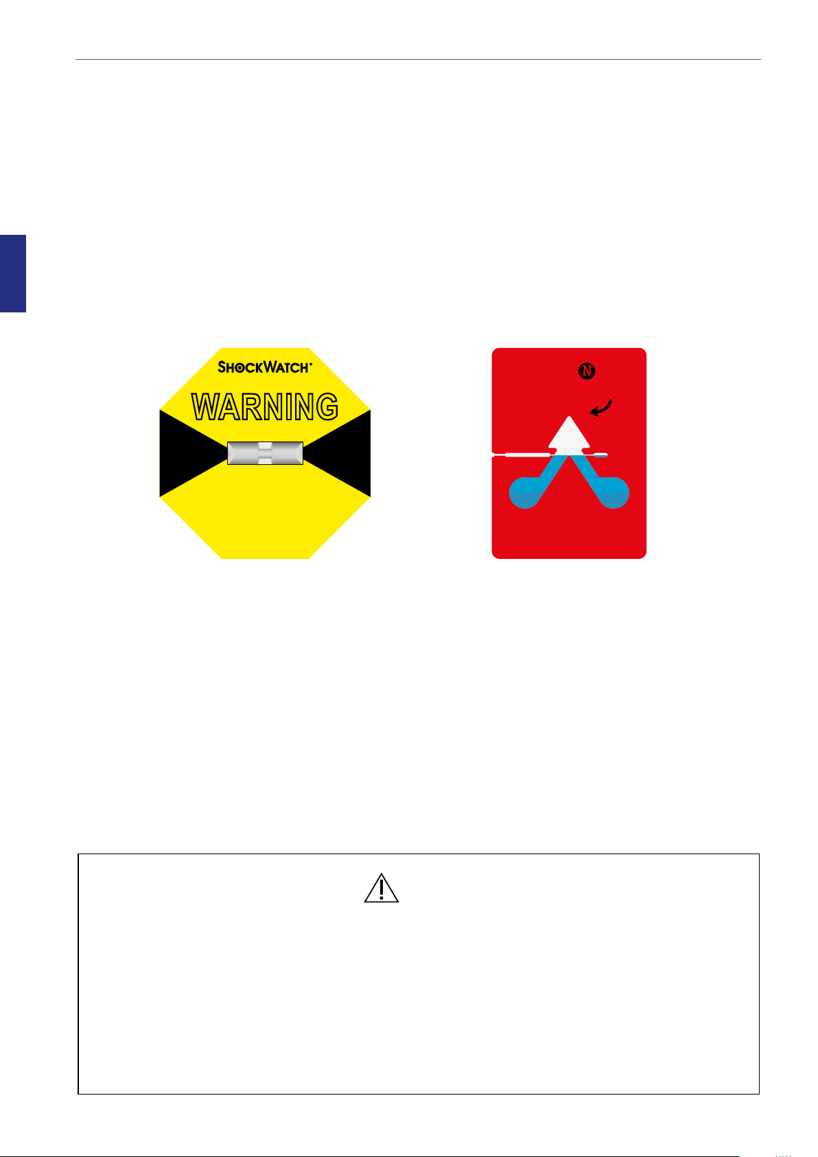
This incubator is transported in a crate and we recommend you inspect its delivery. If the ShockWatch
or TipNTell has been triggered, inform customer service.
Check the contents to ensure all parts listed on the packing list are present.
Placement
The G210 InviCell should be placed on a level, secure surface, away from heaters, coolers,
air-conditioning outlets, mists, splash and direct sunlight. Allow 10cm of clearance on all sides to allow
adequate ventilation.
Allow the G210 to acclimatize for two hours before installation.
To maintain a device setpoint between 35-40°C the preferred ambient temperature should be
between 20-30°C. DO NOT use the incubator at ambient temperatures exceeding 30°C as this may
compromise the incubation process.
This unit is designed for use at altitudes under 2,000 meters.
HANDLE WITH CARE
WARNING
RED INDICATES ROUGH HANDLING.
IF RED, NOTE ON THE BILL OF LADING
AND INSPECT PRODUCT
PRODUCT OF MEDIA RECOVERY
MODEL: L-65 (25g)
MADE IN THE USA
www.shockwatch.com 1.800.527.9497
MADE IN THE U.S.A
BLUE BEADS IN
ARROW INDICATES
CONTAINER WAS
TIPPED OR
MISHANDLED
TELL
TIP
CAUTION
• Installation of the unit should only be performed by an authorized CooperSurgical Service
Technician.
• Never block any of the ventilation holes on the unit.
• Make sure that all devices emitting electromagnetic radiation are kept at a reasonable
distance from the unit in order to avoid any potential interferences.
• Make sure the power circuits used are intended for medical equipment.
• Make sure there is sufficient access to the device for ease of disconnection if required.

Intended Use
11
4
Section 4 - Intended Use
To provide an environment with controlled temperature at or near body temperature and gas level
(CO2, O2and N2), for the development of human gametes and embryos during in vitro fertilization
(IVF) treatment.
Applicable indications for use are subject to the regulations of the country into which the device
is sold and also the availability of the G210 InviCell for clinical use is dependent on the regulatory
approval status of the incubator within that country.
Applicable Part Numbers
Order Code Description
K59500 InviCell Standard Incubator
K60000 InviCell Plus Incubator
Significant Performance Characteristics
The incubator has been developed and optimized for gametes and embryos cultured with an overlay
of either paraffin or mineral oil. Each chamber is designed to contain dishes from one patient only.
Operation Principle
The fertilized egg (zygote) is cultured for up to 6-7 days in a growth medium in the incubator with
a controlled environment (temperature and CO2/O2). It is then implanted in the same or another
woman’s uterus, with the intention of establishing a successful pregnancy.
User Profile
Atrainedhealthprofessional,whohastheappropriate assisted reproductiontechnologiesqualifications.
Only qualified personnel trained in using the G210 InviCell should operate the incubator.
CAUTION: If the equipment is used in a manner not specified by this manual, the
safety of the user may be at risk and the equipment may be damaged. Always use the
equipment as stated in this User Manual.
Operating Environment
To be used at ambient temperature in a medical environment, clinic or hospital laboratory under
normal working conditions.

Intended Use
12
4Ensure the culture dishes
are placed securely in the
correct milled grooves of
the Dish Inserts.
1
23
Dish Inserts
The chambers should only be fitted with special Dish Inserts (1), that allow safe placement of standard
culture dishes (Falcon, Nunc, Vitrolife).
Chamber Heating
Each chamber is heated with K-Systems unique non-inductive EM Neutra™ heating system, which
provides a uniform heat distribution and ensures there is no electro-magnetic field around the embryos/
gametes. All chambers have their own individual sensors to ensure stable temperatures at all times
and unidirectional gas flow across the chambers ensures even gas distribution in each chamber.
Chamber Lid
Each lid has a sensor that, when opened, will disconnect the gas flow to minimize ambient air entering
the chamber. The gas flow restarts immediately after closing the lid.
The silicone plugs (2) in the lid of each chamber are for the collection of gas samples. These plugs
should be replaced when penetrated a maximum of 5 times.
Preparation Chamber
The Preparation Chamber (3) is intended to be used for the equilibration and heating of pre-filled
culture dishes with an oil overlay or flask of oil.
The Preparation Chamber also has a temperature sensor which will disconnect the gas flow when the
lid is opened, to minimize the ingress of ambient air. The gas flow restarts immediately after closing
the lid.
Gas flow to the Preparation Chamber can be disconnected by using the on/off button in system
settings (see page 26).

13
5
Product Overview
Section 5 - Product Overview
Main Components
Components
1 Incubator Chambers
2 Touchscreen
3 Preparation Chamber
4 K-730 Filter
4
2
3
1
G210 InviCell Standard and Plus models - front view
G210 InviCell Standard and Plus models - raised top section

14
5
Product Overview
5
7
On base
of unit
6
89 10
Supplied Accessories for G210 InviCell Standard
• 1 x K-730 Filter
• 2 x HEPA Inline Filter for input gas supply
• 10 Dish Inserts for Nunc®, Falcon®or Vitrolife®
• 2 x Silicone Tube Sealing Rings & Silicone Tube (3m)
• Gas sampling coupling
• 1 power cord
• 1 LAN cable (3m)
• 1 packet of Chamber Lid plugs (10 pieces)
• 1 USB drive containing K-Link software
Components
5 Product label
6 Mains connection with fuse
7 Ventilation holes
8 Gas inlet connectors
9 Alarm output
10 Ethernet connector**
**External computing devices connected to the Ethernet on the unit must only be Limited Power
Source and SELV circuit according to the standards IEC/UL 60950-1.
G210 InviCell Standard Model - back view
(see page 17 for InviCell Plus)

15
5
Product Overview
Accessory Order Codes
Order Code Description
23063-1 Falcon Dish Inserts 1 pc
23064-1 Nunc Dish Inserts 1 pc
22410-1 Nunc Dish Inserts 10 pc
23069 Vitrolife Dish Inserts 1 pc
23070-1 Vitrolife Dish Inserts 10 pc
22412-1 5 x Nunc Dish Inserts and 5 x Falcon Dish Inserts
23071-1 5 x Nunc Dish Inserts and 5 x Vitrolife Dish Inserts
23072-1 5 x Vitrolife Dish Inserts and 5 x Falcon Dish Inserts
23060-1 Dish Insert Nunc pH Online Sensor (Plus models only)
23061-1 Dish Insert Falcon pH Online Sensor (Plus models only)
23079 Dish Insert Vitrolife pH Online Sensor (Plus models only)
59556 K-730 Filter
53830 HEPA Inline Filter
59922 Lid Plugs, bag of 10
59901-1 Lid Seal for culture chambers
59902-1 Lid Seal for Preparation Chamber
59688 Gas sampler coupling
11103 G100 Gas Analyzer
11006 Solid Temperature Sensor (use with K-Systems F100 Thermometer)
59655 XLR6 Receptacle Connector
32903 User Manual
60017 Connector for External CO2sensor MTG (Plus models only)
60014 Connector for External CO2sensor Vaisala (Plus models only)
60018 25 Pin D-Sub male connector prepared for soldering (Plus models
only)
60019 24VDC power supply (Plus models only)

16
5
Product Overview
Specification Table
Criteria Specification
Overall dimensions, (L x W x H) 860mm x 550mm x 180mm
Weight 53kg maximum
Temperature range 35 – 42°C
User interface Touchscreen
User interface functions Digital temperature readout, data logger, temperature
setpoint, calibration, warning for next service
Connections Mains, CO2gas, N2gas, Sampler port, Ethernet, Alarm
Alarms Visual and audible alarm for out of range temperature and gas
Filter (HEPA/ VOC) K-730 Filter
IP class IP30
Overvoltage category Transient overvoltage II
Pollution degree rating for electrical
equipment 2
Power specifications 100 – 240 VAC
Max consumption 270W
Voltage 1/N/PE AC, 100 - 240VAC Class 1 type B
Frequency 50/60 Hz
Current 3.2A
Mains supply voltage fluctuations Up to +/-10 % of the nominal voltage
Fuses 100 - 240V UL Listed
Mains connection T2.7AL
Ambient conditions
Working temperature and humidity 20 – 30°C. Less than 75% RH (non-condensing)
Transport and storage temperature
and humidity
5 – 50°C. Less than 95% RH (non-condensing)
Maximum one week at 50°C

17
6
G210 InviCell Plus
Section 6 - G210 InviCell Plus
G210 InviCell Plus supports external and independent movement and monitoring of the most critical
parameters regarding the performance of culture media, CO2concentration, temperature and
pH measurement.
All external sensors are completely independent of the functions and controls in the G210 InviCell
Plus as they are connected to and powered by instruments independent of the G210 InviCell Plus.
CAUTION: Installations of external sensors must be performed by CooperSurgical or
by persons authorized by CooperSurgical only.
Component
1 Connection for external CO2sensor
2 Connection for external pH monitoring (pH Online™)
3 Data connection for external thermometer and power
4 Power connection for external thermometer and power
External Sensors, pH / CO2
The following external sensors can be used with the G210 InviCell Plus:
• External pH: OCTAX Log & Guard™ from MTG GmbH
• External CO2: OCTAX Log & Guard™ CO2sensor from MTG
GMP251 Carbon Dioxide Probe from Vaisala Oyj
These parts need to be purchased separately, directly from MTG GmbH or Vaisala Oyj.
An external CO2connector for the GMP251 Carbon Dioxide Probe from Vaisala Oyj is enclosed.
Connectors can to be ordered separately.
• OCTAX Log & Guard™ CO2sensor from MTG
• GMP251 Carbon Dioxide Probe from Vaisala Oyj
1
234
G210 InviCell Plus - back view

18
6
G210 InviCell Plus
Dish Insert for pH Online
A special Dish Insert must be used in the chamber were the pH optical fibre sensor is installed. There
are three different Dish Inserts available depending on the dishes used:
• Dish Insert Nunc pH Online Sensor: Order code: 23060-1
• Dish Insert Falcon pH Online Sensor: Order code: 23061-1
• Dish Insert Vitrolife pH Online Sensor: Order code: 23079
External Temperature
You will need:
• 25 Pin D-Sub male connector prepared for soldering
• 24 VDC power supply
Further information is available in the Installation Guide for the G210 InviCell Plus.
Additionally Supplied Accessories for G210 InviCell Plus
• Connector for GMP251 Carbon Dioxide Probe from Vaisala Oyj
• 25 Pin D-Sub male connector prepared for soldering
• 24 VDC power supply

19
7
Set-up
Section 7 - Set-up
Before use, see chapter “Section 9 - Settings”.
Gas Supply
1. The G210 is not supplied sterile and should be cleaned before use. Make sure the gas
input and output ports at the back of the incubator are also cleaned. See “Section 12 -
Maintenance” on page 40.
2. Install the K-730 filter, see “Replacing the K-730 Filter” on page 46.
3. Connect the gas supply via the gas connectors (1) at the back of the unit.
4. Turn on incubator.
5. Make sure the incubation temperature, gas mixture etc, settings are as desired using the
Settings Menu on the touchscreen. After 30 minutes the unit will be at a constant working
temperature and air flow (see “Changing the Temperature Setpoint” on page 24).
6. Set correct date and time before connecting to the network (LAN).
WARNING: Use only pure CO2and pure N2gas. Use of other gases could result in
serious injury. Make sure that gas supply pressures are kept between a minimum of 0.5
bar and a maximum of 1.0 bar.
Factory Settings
The G210 is supplied with the following factory settings
Criteria Setting
Temperature 37.0° C
Gas concentration CO2: 5.0%
O2: 5.0 %
Gas flow* CO2: 1.5 l/h*
N2:7 l/h*
*When G210 is stable and CO2and O2gas concentration setpoints are 5.0%
1

20
8
Basic Operation
Section 8 - Basic Operation
CAUTION: Do not use the incubator if the alarm system of the device has issued a
failure message and the cause of the failure has not been corrected.
It is important that the appropriate Dish Inserts are selected for the culture dishes used (Falcon, Nunc,
Vitrolife) to ensure there is direct contact between the dish and the heated surface.
Dishes which present no opportunity for an air gap between dish and heated surface can be placed
directly on the heated surface with no need for a Dish Insert.
The use of Dish Inserts requires temperature calibration with the Dish Insert in place (see ”Dish Inserts”
on page 12).
1. Place the Dish Inserts in the chamber and close the lid.
2. Wait 30 minutes for the Dish Inserts to heat up.
3. Open the chamber lid.
4. Place the culture dishes containing gametes or embryos on the Dish Inserts ensuring they are
placed securely in the correct milled grooves.
5. Close the lid.
6. Enter the patient ID as per “Edit Chamber Information” on page 22.
Touchscreen Menu
All the unit’s functions and settings are controlled from the touchscreen.
When the power is connected the main screen will appear on the display.
The touchscreen can be operated with gloves.
Function Tabs
Function Details and Settings
Function Controls
Other manuals for G210 InviCell
1
Table of contents
Other K-Systems Accessories manuals