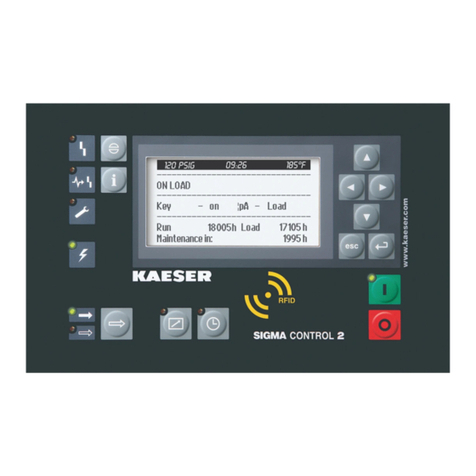
Tab. 1 Operating elements .................................................................................................................... 1
Tab. 2 Display elements ........................................................................................................................ 2
Tab. 3 Main menu overview .................................................................................................................. 3
Tab. 4 Functions overview ..................................................................................................................... 3
Tab. 5 Danger levels and their definition (personal injury) .................................................................... 7
Tab. 6 Danger levels and their definition (damage to property) ............................................................ 7
Tab. 7 Formatting options ...................................................................................................................... 8
Tab. 8 User interface ............................................................................................................................. 9
Tab. 9 Display data ................................................................................................................................ 9
Tab. 10 MCS interfaces ........................................................................................................................... 10
Tab. 11 RFID ........................................................................................................................................... 10
Tab. 12 IOM 1 .......................................................................................................................................... 11
Tab. 13 Power supply specifications ....................................................................................................... 11
Tab. 14 Cable lengths ............................................................................................................................. 11
Tab. 15 Degree of protection, IOM .......................................................................................................... 12
Tab. 16 IOM dimensions ......................................................................................................................... 12
Tab. 17 Pressure transducer ................................................................................................................... 12
Tab. 18 Resistance thermometer ............................................................................................................ 12
Tab. 19 Technical specifications - PROFIBUS ........................................................................................ 13
Tab. 20 Assignment of PROFIBUS interface .......................................................................................... 13
Tab. 21 Technical Specifications - SIGMA CONTROL 2 interface .......................................................... 13
Tab. 22 Assignment of the SIGMA CONTROL 2 interface ...................................................................... 14
Tab. 23 Technical Specifications - Modbus TCP interface ...................................................................... 14
Tab. 24 Assignment of the Modbus TCP interface .................................................................................. 15
Tab. 25 Recommended conductors - Modbus TCP interface ................................................................. 15
Tab. 26 Technical data - DeviceNet communications module ................................................................ 15
Tab. 27 Assigning the DeviceNet interface ............................................................................................. 16
Tab. 28 DeviceNet interface - cabling recommendation .......................................................................... 16
Tab. 29 Technical Specifications - SIGMA CONTROL 2 interface .......................................................... 16
Tab. 30 Assignment of the SIGMA CONTROL 2 interface ...................................................................... 17
Tab. 31 Recommended conductors - SIGMA CONTROL 2 interface ..................................................... 17
Tab. 32 Technical data EtherNet/IP-Interface ......................................................................................... 17
Tab. 33 Configuration of the EtherNet/IP-Interface ................................................................................. 18
Tab. 34 EtherNet/IP-Interface - Cabling recommendation ...................................................................... 18
Tab. 35 Operating elements .................................................................................................................... 22
Tab. 36 Display elements ........................................................................................................................ 23
Tab. 37 RFID reader ................................................................................................................................ 24
Tab. 38 Reset check box status .............................................................................................................. 27
Tab. 39 Check box status ........................................................................................................................ 27
Tab. 40 KAESER CONNECT functions ................................................................................................... 28
Tab. 41 Menu structure of main menu ..................................................................................................... 30
Tab. 42
Status
menu ............................................................................................................................... 33
Tab. 43
Configuration
menu .................................................................................................................... 34
Tab. 44
Communication
menu ................................................................................................................ 37
Tab. 45
Connections
menu ..................................................................................................................... 38
Tab. 46
Components
menu ..................................................................................................................... 39
Tab. 47 SIGMA CONTROL 2 ready states .............................................................................................. 41
Tab. 48 Machine identification ................................................................................................................. 47
Tab. 49 Remote control identification ...................................................................................................... 47
Tab. 50 Machine identification ................................................................................................................. 47
Tab. 51 Supported languages ................................................................................................................. 50
Tab. 52 Date formats ............................................................................................................................... 57
Tab. 53 Settings options for the time format ............................................................................................ 58
Tab. 54 Settings options for the pressure units ....................................................................................... 59
List of Tables
No.: 901700 14 E
Service Manual Controller
SIGMA CONTROL 2 BLOWER ≥ 4.0.X vii


