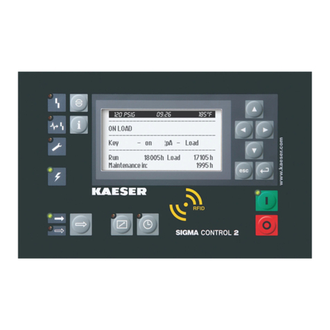
KAESER KOMPRESSOREN SIGMA CONTROL 2 User manual

/KKW/SSC 2.11 en IBA-SIGMA CONTROL DRY
/KKW/SSC 2.11
20200703 102433

1 SIGMA CONTROL 2 Quick installation guide
1.1 Operating elements .......................................................................................................... 1
1.2 Display elements .............................................................................................................. 2
1.3 Main menu – Overview ..................................................................................................... 2
1.4 Functions – Overview ....................................................................................................... 3
2 Regarding this document
2.1 Using this document ......................................................................................................... 5
2.2 Copyright .......................................................................................................................... 5
2.2.1 Software .............................................................................................................. 5
2.3 Certification ...................................................................................................................... 6
2.4 Updating the operating manual ........................................................................................ 6
2.5 Symbols and labels .......................................................................................................... 6
2.5.1 Warnings ............................................................................................................. 6
2.5.2 Potential damage warnings ................................................................................ 7
2.5.3 Other alert notes and their symbols .................................................................... 8
3 Technical Specifications
3.1 Controller SIGMA CONTROL 2 ....................................................................................... 9
3.1.1 User interface with display, CPU and interfaces ................................................. 9
3.1.2 Input/output modules .......................................................................................... 11
3.1.3 Sensors ............................................................................................................... 13
4 Safety and Responsibility
4.1 Basic instructions ............................................................................................................. 14
4.2 Specified use .................................................................................................................... 14
4.3 Improper use .................................................................................................................... 14
5 Design and Function
5.1 Controller overview .......................................................................................................... 15
5.2 Operating panel ................................................................................................................ 16
5.2.1 Operating elements ............................................................................................ 16
5.2.2 Display elements ................................................................................................ 17
5.2.3 RFID reader ........................................................................................................ 18
5.3 Display ............................................................................................................................. 19
5.3.1 Operating mode .................................................................................................. 19
5.3.2 Main menu .......................................................................................................... 20
5.3.3 Setting parameters ............................................................................................. 21
5.3.4 Activating keys with check boxes ....................................................................... 21
5.4 Access rights .................................................................................................................... 21
5.5 KAESER CONNECT ........................................................................................................ 22
5.6 Menu overview ................................................................................................................. 23
5.6.1 Operating mode .................................................................................................. 23
5.6.2 Menu structure .................................................................................................... 24
5.7 Additional information ....................................................................................................... 34
5.8 Operating points and control modes ................................................................................ 34
5.8.1 Machine operating points .................................................................................... 34
5.8.2 Control modes .................................................................................................... 35
5.8.3 Variable speed drive with frequency converter (SFC) ........................................ 36
6 Installation and Operating Conditions
6.1 Maintaining ambient conditions ........................................................................................ 37
6.2 Installation conditions ....................................................................................................... 37
7 Installation
7.1 Reporting Transport Damage ........................................................................................... 38
7.2 Machine identification ....................................................................................................... 38
Contents
No.: 9_9451 04 E
User Manual Controller
SIGMA CONTROL 2 SCREW DRY ≥ 3.3.X i

8 Initial Start-up
8.1 Outline .............................................................................................................................. 39
8.2 Setting the controller ........................................................................................................ 39
8.2.1 Selecting menu options ...................................................................................... 40
8.2.2 Setting the language ........................................................................................... 42
8.2.3 Noting the user name ......................................................................................... 43
8.2.4 User log-in with RFID Equipment Card ............................................................... 43
8.2.5 Generating a password ....................................................................................... 44
8.2.6 Manual user log-in .............................................................................................. 45
8.2.7 Create the master RFID Equipment Card ........................................................... 46
8.2.8 Checking/setting time and date .......................................................................... 47
8.2.9 Set the time zone ................................................................................................ 49
8.2.10 Set display formats ............................................................................................. 49
8.2.11 Setting the display illumination ........................................................................... 52
8.2.12 Setting the contrast and the brightness .............................................................. 53
8.2.13 Activating the remote control .............................................................................. 53
8.2.14 IP configuration .................................................................................................. 54
8.2.15 Setting the e-mail function .................................................................................. 55
8.2.16 Setting the time server ........................................................................................ 57
8.3 KAESER CONNECT benefits .......................................................................................... 58
8.3.1 Open KAESER CONNECT ................................................................................. 59
8.3.2 System status menu ........................................................................................... 60
8.3.3 Graphs menu ...................................................................................................... 62
8.3.4 Messages menu ................................................................................................. 64
8.3.5 I/O display menu ................................................................................................. 64
8.3.6 User management menu .................................................................................... 65
8.3.7 Settings menu ..................................................................................................... 68
8.3.8 Save data menu .................................................................................................. 69
8.3.9 Data recording menu .......................................................................................... 69
8.3.10 KAESER CONNECT exit .................................................................................... 70
8.4 Pressure parameters of the machine ............................................................................... 71
8.4.1 Displaying pressure parameters ......................................................................... 72
8.4.2 Setting pressure parameters .............................................................................. 73
8.5 Machine start and machine stop ...................................................................................... 78
8.5.1 Automatic start/stop in timer mode .................................................................... 78
8.5.2 Setting the company shut-down ......................................................................... 82
8.5.3 Controlling machine from a remote location ....................................................... 83
8.6 Control modes .................................................................................................................. 85
8.6.1 Setting the control mode ..................................................................................... 85
8.6.2 Setting the DUAL control mode .......................................................................... 86
8.6.3 Setting the QUADRO control mode .................................................................... 87
8.7 Refrigeration dryer ........................................................................................................... 88
8.7.1 Setting the operating mode ................................................................................. 88
8.7.2 Setting and activating messages ........................................................................ 89
8.8 Rotation dryer ................................................................................................................... 90
8.8.1 Fault message for pressure dew point ................................................................ 90
8.8.2 Setting additional parameters in the
Pressure dew point
menu ......................... 92
8.8.3 Setting the parameter for an additional fan ........................................................ 93
8.9 Setting the machine for local mode .................................................................................. 94
8.9.1 Menu Load control .............................................................................................. 94
8.9.2 Setting the nominal pressure change via timing program .................................. 94
8.9.3 Setting the nominal pressure change via timer ................................................... 97
8.10 Setting the machine for master control operation ............................................................ 100
8.10.1 Overview of the different master operating modes ............................................. 100
Contents
ii
User Manual Controller
SIGMA CONTROL 2 SCREW DRY ≥ 3.3.X No.: 9_9451 04 E

8.10.2 SAM 4.0 mode .................................................................................................... 100
8.10.3 Setting PROFIBUS operation (SIGMA AIR MANAGER) .................................... 103
8.10.4 Interconnection of two machines in master/slave operation ............................... 111
8.10.5 Configuring interconnected operation using the LOAD remote contact (e.g.
SIGMA AIR MANAGER BASIC) .........................................................................
118
8.10.6 Setting the master control with local/LOAD remote contact ............................... 120
8.10.7 Setting the nominal pressure pre-selection via remote contact .......................... 122
8.10.8 Examples of time settings for equal overall load ............................................... 123
8.11 Setting input and output signals ....................................................................................... 125
8.11.1 Output operational states of machine on digital outputs ..................................... 125
8.11.2 Output input signals on the display ..................................................................... 127
8.11.3 Output measured values on the display ............................................................. 131
8.12 Activating remote acknowledgement ............................................................................... 136
8.12.1 Setting the remote acknowledgement function ................................................... 137
8.12.2 Activating the remote control .............................................................................. 137
8.12.3 Assigning an input .............................................................................................. 138
8.13 Linking to an external pressure transducer ...................................................................... 138
8.13.1 Network actual pressure menu ........................................................................... 139
8.13.2 Assigning an input to an external pressure transducer ...................................... 139
8.14 Water system ................................................................................................................... 140
8.15 Commissioning the machine ............................................................................................ 141
9 Operation
9.1 Switching the machine on and off .................................................................................... 143
9.1.1 Switching on ....................................................................................................... 143
9.1.2 Switching off ....................................................................................................... 144
9.2 Switching off in an emergency ......................................................................................... 144
9.3 Acknowledging alarm and warning messages ................................................................. 145
9.4 Displaying messages ....................................................................................................... 146
9.4.1 Status – Messages menu ................................................................................... 147
9.5 Displaying the current operating mode ............................................................................ 149
9.6 Setting the working pressure ............................................................................................ 150
9.7 Displaying analogue data ................................................................................................. 150
9.8 Displaying operating data ................................................................................................. 152
9.8.1 Checking the operating hours ............................................................................. 152
9.8.2 Controlling the switching cycles .......................................................................... 154
9.9 Setting the maintenance interval ...................................................................................... 155
9.10 Checking the safety valve ................................................................................................ 156
9.11 Excessive temperature shut-down test ............................................................................ 162
9.12 Setting the target value for the compressed air discharge temperature .......................... 166
9.12.1 Setting the profile ................................................................................................ 166
9.12.2 Setting the T4w setpoint ..................................................................................... 167
9.12.3 Setting the operating mode ................................................................................. 168
9.13 Setting the setpoint for the pressure dew point ................................................................ 169
9.13.1 Setting the profile ................................................................................................ 169
9.13.2 Setting the M85w setpoint .................................................................................. 170
9.13.3 Setting the operating mode ................................................................................. 171
9.14 Adjusting the pressure dew point ..................................................................................... 171
9.14.1 Setting the profile ................................................................................................ 172
9.14.2 Setting "f" parameters ......................................................................................... 172
9.14.3 Setting the operating mode ................................................................................. 173
9.15 Save data ......................................................................................................................... 174
10 Fault Recognition and Rectification
10.1 Basic instructions ............................................................................................................. 177
Contents
No.: 9_9451 04 E
User Manual Controller
SIGMA CONTROL 2 SCREW DRY ≥ 3.3.X iii

10.2 Interpreting alarm messages ............................................................................................ 177
10.3 Interpreting warning messages ........................................................................................ 191
10.4 Interpreting operating messages ...................................................................................... 203
10.5 Interpreting diagnostic messages .................................................................................... 208
10.6 Interpreting system messages ......................................................................................... 208
11 Maintenance
11.1 Changing the battery ........................................................................................................ 209
12 Spares, Operating Materials, Service
12.1 Note the nameplate .......................................................................................................... 210
12.2 KAESER AIR SERVICE ................................................................................................... 210
12.3 Service Addresses ........................................................................................................... 210
12.4 Displaying the version number, machine model, material number and serial number ..... 210
13 Decommissioning, Storage and Transport
13.1 De-commissioning ............................................................................................................ 212
13.2 Packing ............................................................................................................................ 212
13.3 Storage ............................................................................................................................. 212
13.4 Transporting ..................................................................................................................... 212
13.5 Battery removal and disposal ........................................................................................... 212
Contents
iv
User Manual Controller
SIGMA CONTROL 2 SCREW DRY ≥ 3.3.X No.: 9_9451 04 E

Fig. 1 Operating elements .................................................................................................................... 1
Fig. 2 Display elements ........................................................................................................................ 2
Fig. 3 MCS interfaces ........................................................................................................................... 10
Fig. 4 MCS system design with IOM .................................................................................................... 15
Fig. 5 Operating elements .................................................................................................................... 16
Fig. 6 Display elements ........................................................................................................................ 17
Fig. 7 RFID reader ................................................................................................................................ 18
Fig. 8 KAESER CONNECT for SIGMA CONTROL 2 ........................................................................... 22
Fig. 9 Back of the RFID Equipment Card ............................................................................................. 43
Fig. 10 User log-in with RFID Equipment Card ...................................................................................... 43
Fig. 11 User log-in with RFID Equipment Card ...................................................................................... 44
Fig. 12 Manual user log-on ..................................................................................................................... 46
Fig. 13 Log-in mask ................................................................................................................................ 59
Fig. 14 KAESER CONNECT for SIGMA CONTROL 2 ........................................................................... 60
Fig. 15 Select language: window ............................................................................................................ 60
Fig. 16
System status
menu ................................................................................................................... 61
Fig. 17 Main menu .................................................................................................................................. 61
Fig. 18
Graphs
(illustration similar) ......................................................................................................... 62
Fig. 19 Control keys ............................................................................................................................... 63
Fig. 20
Messages
(illustration similar) .................................................................................................... 64
Fig. 21
I/O display
(illustration similar) ................................................................................................... 65
Fig. 22
User management
menu ............................................................................................................ 66
Fig. 23
Log on for write access:
window ................................................................................................ 66
Fig. 24
User management
menu ............................................................................................................ 67
Fig. 25
Settings
menu ............................................................................................................................ 68
Fig. 26
Backup
menu ............................................................................................................................. 69
Fig. 27
Data recording
menu .................................................................................................................. 70
Fig. 28 Pressure rise in frequency-controlled machines ........................................................................ 76
Fig. 29 Wiring of the Profibus connection ............................................................................................... 104
Fig. 30 Electrical diagram example with SIGMA AIR MANAGER .......................................................... 105
Fig. 31 Communication interface ............................................................................................................ 106
Fig. 32 Insert the communication module. ............................................................................................. 107
Fig. 33 Front plate communication module Profibus .............................................................................. 108
Fig. 34 Direct connection of two SIGMA CONTROL 2 ........................................................................... 113
Fig. 35 LOAD remote contact ................................................................................................................. 118
Fig. 36 Switching the compressed air station on and off ........................................................................ 143
Fig. 37 Switching off in an emergency ................................................................................................... 144
Fig. 38 Acknowledging messages .......................................................................................................... 145
List of Illustrations
No.: 9_9451 04 E
User Manual Controller
SIGMA CONTROL 2 SCREW DRY ≥ 3.3.X v

List of Illustrations
vi
User Manual Controller
SIGMA CONTROL 2 SCREW DRY ≥ 3.3.X No.: 9_9451 04 E

Tab. 1 Operating elements .................................................................................................................... 1
Tab. 2 Display elements ........................................................................................................................ 2
Tab. 3 Main menu – Overview ............................................................................................................... 2
Tab. 4 Functions – Overview ................................................................................................................. 3
Tab. 5 Danger levels and their definition (personal injury) .................................................................... 7
Tab. 6 Danger levels and their definition (damage to property) ............................................................ 7
Tab. 7 Formatting options ...................................................................................................................... 8
Tab. 8 User interface ............................................................................................................................. 9
Tab. 9 Display data ................................................................................................................................ 9
Tab. 10 MCS interfaces ........................................................................................................................... 10
Tab. 11 RFID ........................................................................................................................................... 10
Tab. 12 SC2IOM-1 .................................................................................................................................. 11
Tab. 13 SC2IOM-2 .................................................................................................................................. 11
Tab. 14 SC2IOM-3 .................................................................................................................................. 12
Tab. 15 Power supply specifications ....................................................................................................... 12
Tab. 16 Cable lengths ............................................................................................................................. 12
Tab. 17 Degree of protection, IOM .......................................................................................................... 12
Tab. 18 IOM dimensions ......................................................................................................................... 13
Tab. 19 Pressure transducer ................................................................................................................... 13
Tab. 20 Resistance thermometer ............................................................................................................ 13
Tab. 21 Operating elements .................................................................................................................... 16
Tab. 22 Display elements ........................................................................................................................ 17
Tab. 23 RFID reader ................................................................................................................................ 18
Tab. 24 Data in the header depending on the machine type ................................................................... 19
Tab. 25 Reset check box status .............................................................................................................. 21
Tab. 26 Check box status ........................................................................................................................ 21
Tab. 27 KAESER CONNECT functions ................................................................................................... 22
Tab. 28 Menu structure of main menu ..................................................................................................... 24
Tab. 29
Status
menu ............................................................................................................................... 28
Tab. 30
Configuration
menu .................................................................................................................... 29
Tab. 31
I/O periphery
menu ..................................................................................................................... 31
Tab. 32
Communication
menu ................................................................................................................ 32
Tab. 33
Components
menu ..................................................................................................................... 33
Tab. 34 Compressor information depending on the type ........................................................................ 34
Tab. 35 Option-dependent information .................................................................................................... 34
Tab. 36 Machine identification ................................................................................................................. 38
Tab. 37 Remote control identification ...................................................................................................... 38
Tab. 38 Machine identification ................................................................................................................. 38
Tab. 39 Supported languages ................................................................................................................. 42
Tab. 40 Date formats ............................................................................................................................... 49
Tab. 41 Possible settings for the time format .......................................................................................... 50
Tab. 42 Possible settings for the pressure unit ....................................................................................... 51
Tab. 43 Possible settings for the temperature unit .................................................................................. 51
Tab. 44 Display illumination ..................................................................................................................... 52
Tab. 45 Network parameters ................................................................................................................... 55
Tab. 46 E-mail parameters ...................................................................................................................... 56
Tab. 47 Control key functions .................................................................................................................. 63
Tab. 48 Compressor pressure parameters .............................................................................................. 71
Tab. 49 Setting limits for
Setpoint pressure
............................................................................................. 73
Tab. 50 Pressure condition for LOAD ...................................................................................................... 73
Tab. 51 Pressure conditions for IDLE ...................................................................................................... 73
Tab. 52 Setting limits for
Setpoint pressure
............................................................................................. 74
Tab. 53 Pressure condition for LOAD ...................................................................................................... 74
Tab. 54 Pressure conditions for IDLE ...................................................................................................... 74
List of Tables
No.: 9_9451 04 E
User Manual Controller
SIGMA CONTROL 2 SCREW DRY ≥ 3.3.X vii
Tab. 55 Displaying and setting parameters ............................................................................................. 75
Tab. 56 Example: activated output .......................................................................................................... 76
Tab. 57 Settings for machine start and machine stop ............................................................................. 78
Tab. 58 User-defined clock programme machine ON/OFF ..................................................................... 79
Tab. 59 Example of a machine ON/OFF clock program .......................................................................... 80
Tab. 60 Operating modes in local operating mode (local mode) ............................................................. 94
Tab. 61 User-defined timing program for nominal pressure change ....................................................... 95
Tab. 62 Example: Switching points, nominal pressure change ............................................................... 95
Tab. 63 Master control – overview ........................................................................................................... 100
Tab. 64 Parameters for monitoring for communication malfunction ........................................................ 103
Tab. 65 Pin assignment of SUB-D 9-pole interface on the Profibus module ........................................... 104
Tab. 66 Master-slave settings ................................................................................................................. 112
Tab. 67 Example for a clock program for equal duty cycling during the day ........................................... 124
Tab. 68 Example for a timing program for equal duty cycling during the week ....................................... 124
Tab. 69 Assigned output signals ............................................................................................................. 125
Tab. 70 Logic settings ............................................................................................................................. 129
Tab. 71 Assigned analogue measured values ........................................................................................ 131
Tab. 72 Transmitting a pressure transducer value .................................................................................. 138
Tab. 73 Control valves and water pump operating modes ...................................................................... 140
Tab. 74 Check list for starting the machine ............................................................................................. 141
Tab. 75 Message sequence 1 ................................................................................................................. 145
Tab. 76 Message sequence 2 ................................................................................................................. 145
Tab. 77 Information of a message ........................................................................................................... 146
Tab. 78 Message abbreviations .............................................................................................................. 147
Tab. 79 Operating mode display ............................................................................................................. 149
Tab. 80 Abbreviation of operating modes ................................................................................................ 149
Tab. 81 Check box status ........................................................................................................................ 160
Tab. 82 Check box status ........................................................................................................................ 165
Tab. 83 Option description and setting .................................................................................................... 166
Tab. 84 Option description and setting .................................................................................................... 169
Tab. 85 Option description and setting .................................................................................................... 172
Tab. 86 Alarm messages and remedies .................................................................................................. 177
Tab. 87 Warning messages and remedies .............................................................................................. 191
Tab. 88 Operating messages .................................................................................................................. 203
Tab. 89 System messages and remedies ............................................................................................... 208
List of Tables
viii
User Manual Controller
SIGMA CONTROL 2 SCREW DRY ≥ 3.3.X No.: 9_9451 04 E

1 SIGMA CONTROL 2 Quick installation guide
1.1 Operating elements
Fig. 1 Operating elements
Item Designation Function
1«Up» Scrolls up the menu options. Increases a parameter value.
2«Left» Jumps to the left.
Moves the cursor position to the left.
3«Right» Jumps to the right.
Moves the cursor position to the right.
4«Down» Scrolls down the menu options.
Reduces a parameter value.
5«Escape» Returns to the next higher menu option level.
Exits the edit mode without saving.
6«Enter» Jumps to the selected submenu option.
Exits the edit mode and saves.
7«ON» Switches the machine on.
8«OFF» Switches the machine off.
10 RFID RFID reader for user log-in with RFID Equipment Card.
11 «Time control» Switches the time control on and off.
12 «Remote control» Switches the remote control on and off.
13 «LOAD/IDLE» Toggles between the LOAD and IDLE modes.
19 «Information» Displays the event memory.
21 «Acknowledgement» Confirms/acknowledges alarms and warning messages.
If permissible: Resets the fault counter (RESET).
Tab. 1 Operating elements
1 SIGMA CONTROL 2 Quick installation guide
1.1 Operating elements
No.: 9_9451 04 E
User Manual Controller
SIGMA CONTROL 2 SCREW DRY ≥ 3.3.X 1

1.2 Display elements
Fig. 2 Display elements
Item Designation Function
7
ON
Display illuminates green when the machine switched on.
9
Display
Graphic display with 8 lines and 30 characters per line.
11
Time control
Continuous green light when the machine is controlled by the timer.
12
Remote control
Continuous green light when the machine is in remote control.
14
IDLE
Continuous green light when the machine is running in IDLE. Flashes
when the «LOAD/IDLE» toggle key is pressed.
15
LOAD
Continuous green light when the machine is running in LOAD.
16
Voltage applied to
controller
Continuous green light when voltage is applied to the controller.
17
Warning
Flashes in yellow in the following events:
■ Maintenance necessary
■ Warning message
18
Communications error
Continuous red light to indicate a faulty communication connection
without machine shut-down.
20
Fault
Flashes red to indicate a machine fault.
Continuous red light after acknowledgement.
Tab. 2 Display elements
1.3 Main menu – Overview
Press «Up» / «Down» / «Enter» to open the main menu.
Menu No. Menu name Function
1 Status Displays messages, statistics and status information
1 SIGMA CONTROL 2 Quick installation guide
1.2 Display elements
2
User Manual Controller
SIGMA CONTROL 2 SCREW DRY ≥ 3.3.X No.: 9_9451 04 E

Menu No. Menu name Function
2 Performance data Displays measured data of the machine and its components (e.g.,
motors)
3 Operating data Displays operating hours, switching cycles and energy data
4 Maintenance Displays maintenance data of the machine and its components
5 Configuration Setting of machine parameters, compressed air system and acces‐
sories
6 Compressor clock Setting the time control
7 User Manual user log-in and password administration
8 Communication Setting the Ethernet interface, COM modules and control technolo‐
gy connection
9 Machine test Safety valve / temperature sensor test and shut-down in the event
of excessive temperature
10 Components Display of settings on machine components, e.g. the power switch‐
ing
Tab. 3 Main menu – Overview
See Chapter 5.6.2 for the complete menu structure
1.4 Functions – Overview
Function Menu
No.
Steps Chapter
Setting the con‐
trast
Main
menu
Press and hold «Information» – «Up» / «Down» 8.2.12
Setting the bright‐
ness
Main
menu
Press and hold «Information» – «Left» / «Right» 8.2.12
Setting the lan‐
guage
Main
menu
«Enter» – «Up» – «Enter» – «Up» / «Down» 8.2.2
Setting date, time
and time zone
5.1.1
<Configuration – General>
8.2.8
Identification with
RFID Equipment
Card
– 8.2.4
Setting pressure
parameters
5.2.1
<Configuration – Compressed air system – Pressure settings
– pA/pB>
8.4
Setting the
«time control»
6
<Compressor clock – Setting timing program>
8.5.1
Activating the
«time control»
key
6
<Compressor clock – Key clock – ☑>
8.5.1.3
Activating
«time control»
– Activate the «Time control» key – Press «Time control» key 8.5.1.4
1 SIGMA CONTROL 2 Quick installation guide
1.4 Functions – Overview
No.: 9_9451 04 E
User Manual Controller
SIGMA CONTROL 2 SCREW DRY ≥ 3.3.X 3

Function Menu
No.
Steps Chapter
Activate
the «Remote»
key
5.2.2
5.1.2.1
5.1.3
<Configuration – Compressor start – Compressor ON – Key
remote – ☑>
8.2.13
Activating the
«remote control»
– Activate the «Remote» key – Press «Remote» key 8.2.13
Setting the con‐
trol mode
5.2.4
<Configuration – Control mode – Local mode – Control mode
wählen>
8.6.1
Setting company
shut-down period
5.1.2.2
<Configuration – Compressor start – Compressor OFF –
Holidays – Start/End/☑>
8.5.2
Displaying oper‐
ating data
3
<Operating data – Operating hours / Switching cycles>
9.8
Setting the main‐
tenance interval
4
<Maintenance – Select/set component>
9.9
Check the safety
valve
9.1 For the test process, see Chapter 9.10
Overtemperature
shut-down test
9.1 For the test process, see Chapter: 9.11
Fault messages 1.1.1 A fault message causes the machine to shut down. The
Fault
LED flashes red. Fault messages are identified with the let‐
ter A. Example:
<0002 S k 31.12.17 13:14:15 Compressor motor T > %t>
10.2
Warning messag‐
es
1.1.1 If maintenance work is to be carried out or if the warning is
displayed before an alarm, the yellow
warning
LED flashes.
Warning messages are identified with the letter W.
10.3
Operational mes‐
sages
1.1.1 Operational messages provide information about the current
operational state of the machine. Operational messages are
identified with the letter O.
10.4
Diagnostic mes‐
sages
1.1.1 A diagnostic message causes the machine to shut down.
They provide information on the status of the controller, the
connected input and output modules and support the
KAESER SERVICE in trouble-shooting. Diagnostic messag‐
es are identified with the letter D.
10.5
System messag‐
es
1.1.1 A system message causes the machine to shut down. Sys‐
tem messages are identified with the letter Y.
10.6
Tab. 4 Functions – Overview
Settings can be made after log-in with the RFID Equipment Card and access level 2.
1 SIGMA CONTROL 2 Quick installation guide
1.4 Functions – Overview
4
User Manual Controller
SIGMA CONTROL 2 SCREW DRY ≥ 3.3.X No.: 9_9451 04 E

2 Regarding this document
2.1 Using this document
The operating manual contains important information to the entire life cycle of
SIGMA CONTROL 2.
The operating manual is a component of the product.
➤ Keep the manual in a safe place throughout the life of SIGMA CONTROL 2.
➤ Pass the manual on to the next owner/user of the machine.
➤ Ensure that all amendments received are inserted into the operating manual.
2.2 Copyright
This operating manual is protected by copyright. Any queries regarding the use or duplication of
this documentation should be referred to KAESER. Correct use of information will be fully suppor‐
ted.
2.2.1 Software
The software used in SIGMA CONTROL 2 contains copyright-protected software packages which
are licensed as Open Source.
A copy of these licenses is contained in SIGMA CONTROL 2.
Display the licenses by pointing your browser to the "COPYING" file in the root directory of
SIGMA CONTROL 2.
URL:
http:// <Hostname>/COPYING
The licenses can be also found under these addresses:
http://www.gnu.org/licenses
http://code.google.com/p/curve25519-donna/
Within three years from receipt of SIGMA CONTROL 2, you may obtain the complete source code
of the copyright-protected software packages by sending a corresponding order to the following ad‐
dress:
Technical Office Electrical Design
KAESER KOMPRESSOREN SE
96450 Coburg, Postfach 2143
Germany
This offer is valid for anybody having this information.
2 Regarding this document
2.1 Using this document
No.: 9_9451 04 E
User Manual Controller
SIGMA CONTROL 2 SCREW DRY ≥ 3.3.X 5

2.3 Certification
This product has the following approvals:
■ This equipment has been tested and found to comply with the limits for a Class B digital de‐
vice, pursuant to part 15 of the FCC Rules. These limits are designed to provide reasonable
protection against harmful interference in a residential installation. This equipment generates,
uses and can radiate radio frequency energy and, if not installed and used in accordance with
the instructions, may cause harmful interference to radio communications. However, there is
no guarantee that interference will not occur in a particular installation. If this equipment does
cause harmful interference to radio or television reception, which can be determined by turning
the equipment off and on, the user is encouraged to try to correct the interference by one or
more of the following measures:
─ Reorient or relocate the receiving antenna.
─ Increase the separation between the equipment and receiver.
─ Connect the equipment into an outlet on a circuit different from that to which the receiver is
connected.
─ Consult the dealer or an experienced radio/TV technician for help.
■ This device complies with part 15 of the FCC rules. The operation is subject to the following
two conditions:
─ this device may not cause harmful interference, and
─ this device must accept any interference received, including interference that may cause
undesired operation.
■ This device fulfils the provisions of the Industry Canada Licence, with the exception of the RSS
rules. The operation is subject to the following two conditions:
─ this device may not cause harmful interference, and
─ this device must accept any interference received, including interference that may cause
undesired operation.
In order to ensure permanent compliance with the FCC rules, unless explicitly approved by
the authority responsible for compliance with the provisions, no changes must be carried out
(for example: when connecting to computers or peripheral equipment use shielded cables on‐
ly).
2.4 Updating the operating manual
Go to our website http://www.kaeser.com/sc2manual to find the latest version of the operating
manual.
➤ Download the desired operating manual from our server and forward it to your operators.
2.5 Symbols and labels
➤ Please note the symbols and labels used in this document.
2.5.1 Warnings
Warnings indicate danger potentially resulting in personal injury, if the measures specified are not
taken.
2 Regarding this document
2.3 Certification
6
User Manual Controller
SIGMA CONTROL 2 SCREW DRY ≥ 3.3.X No.: 9_9451 04 E

Warning notices indicate three levels of danger identified by the corresponding signal word:
Signal term Meaning Consequences of non-compliance
DANGER Warns of imminent danger Will very likely result in death or severe injury
WARNING Warns of potentially imminent danger May result in death or severe injury
CAUTION Warns of a potentially dangerous situa‐
tion
May result in moderate physical injury
Tab. 5 Danger levels and their definition (personal injury)
Warning notices preceding a chapter apply to the entire chapter, including all sub-sections.
Example:
DANGER
The type and source of the imminent danger is shown here!
The possible consequences of ignoring a warning are shown here.
The word "DANGER" indicates that death or severe injury can very likely result from ignoring
the warning.
➤ The measures required to protect yourself from danger are shown here.
Warning notes referring to a sub-section or the subsequent step are integrated into the procedure
and numbered as a step.
Example:
1. WARNING!
The type and source of the imminent danger is shown here!
The possible consequences of ignoring a warning are shown here.
The word "WARNING" indicates that death or severe injury may result from ignoring the warn‐
ing.
➤ The measures required to protect yourself from danger are shown here.
2. Always read and comply with warning instructions.
2.5.2 Potential damage warnings
Contrary to the warnings shown above, damage warnings do not indicate a potential personal in‐
jury.
Warning notices for damages are identified by their signal term.
Signal term Meaning Consequences of non-compliance
NOTE Warns of a potentially dangerous situation Damage to property is possible
Tab. 6 Danger levels and their definition (damage to property)
Example:
NOTICE
The type and source of the imminent danger is shown here!
Potential effects when ignoring the warning are indicated here.
➤ The protective measures against the damages are shown here.
➤ Carefully read and fully comply with warnings against damages.
2 Regarding this document
2.5 Symbols and labels
No.: 9_9451 04 E
User Manual Controller
SIGMA CONTROL 2 SCREW DRY ≥ 3.3.X 7

2.5.3 Other alert notes and their symbols
The meaning of names is emphasised by different formatting. Depending on the font, not all for‐
matting options can be realised.
Designation Formatting Example
Operating point UPPER CASE LOAD
Item number ... Open valve 4
Display
italic ON
LED
Key « ... » «ON» key
Menu option
< ... > <Configuration>
Menu path
<Menu 1 – Menu 2 – ...> <Configuration – Pressure control>
activated ... The minutes display flashes. 00:00:00
Tab. 7 Formatting options
This symbol identifies particularly important information.
Material Here you will find details on special tools, operating materials or spare parts.
Precondition Here you will find conditional requirements necessary to carry out the task.
The conditions relevant to safety shown here will help you to avoid dangerous situations.
➤ This symbol denotes lists of actions comprising one stage of a task.
Operating instructions with several steps are numbered in the sequence of the operating steps.
Information referring to potential problems is identified by a question mark.
The cause is specified in the help text ...
➤ ... as is a solution.
This symbol identifies important information or measures regarding the protection of the envi‐
ronment.
Further information Further subjects are introduced here.
2 Regarding this document
2.5 Symbols and labels
8
User Manual Controller
SIGMA CONTROL 2 SCREW DRY ≥ 3.3.X No.: 9_9451 04 E

3 Technical Specifications
3.1 Controller SIGMA CONTROL 2
Industrial PC
■ Internal temperature monitoring
■ Internal undervoltage monitoring
■ Battery-buffered real-time clock
─ Battery service life: more than 10 years
─ Battery replaceable
3.1.1 User interface with display, CPU and interfaces
User interface
Characteristic Value
Material Plastics
Width [mm] 190
Height [mm] 130
Depth [mm] 45
Number of membrane keys 13
Number of LEDs 9
Degree of protection, control cabinet exterior IP 54
Degree of protection, control cabinet interior IP 20
Voltage [V DC] 24
Current [A] 0.3
Voltage source Input/output module
Tab. 8 User interface
Display
Characteristic Value
Graphical display [px] 255 x 128
Width [mm] 82
Height [mm] 41
Maximum number of lines/characters 8/30
Colours Black/white with grey scale
Lighting LED backlit
px ≙ pixel
Tab. 9 Display data
3 Technical Specifications
3.1 Controller SIGMA CONTROL 2
No.: 9_9451 04 E
User Manual Controller
SIGMA CONTROL 2 SCREW DRY ≥ 3.3.X 9

Fig. 3 MCS interfaces
Identification Interface Connection
X1 Ethernet 10/100 Base T RJ 45 socket
X2 I/O bus 9-pole SUB-D pins
X3 RS485–FC (USS interface) 9-pole SUB-D socket
X4 Com modules,
slot for communications module
Module optional for:
PROFIBUS, PROFINET, Modbus
RTU, Modbus TCP, DeviceNet,
EtherNet/IP
X5 SD card, SD card slot SD/SDHC card
X6 FE Functional earth (FE)
The positions of the interfaces X1–X6 are marked on the rear of the controller.
Tab. 10 MCS interfaces
Identification with RFID Equipment Card
Characteristic Value
Hardware on the SIGMA CONTROL 2 controller RFID reader
Hardware (external) RFID Equipment Card
Recognition distance [m] Max. 0.05
Frequency [MHz] 13.56
Emitted maximum transmitting power at 10 m dis‐
tance [dB(µA/m)]
11
Tab. 11 RFID
3 Technical Specifications
3.1 Controller SIGMA CONTROL 2
10
User Manual Controller
SIGMA CONTROL 2 SCREW DRY ≥ 3.3.X No.: 9_9451 04 E
Other manuals for SIGMA CONTROL 2
6
Table of contents
Other KAESER KOMPRESSOREN Controllers manuals

KAESER KOMPRESSOREN
KAESER KOMPRESSOREN SIGMA CONTROL 2 User manual

KAESER KOMPRESSOREN
KAESER KOMPRESSOREN SIGMA CONTROL 2 User manual

KAESER KOMPRESSOREN
KAESER KOMPRESSOREN SIGMA CONTROL 2 User manual

KAESER KOMPRESSOREN
KAESER KOMPRESSOREN SIGMA CONTROL 2 User manual

KAESER KOMPRESSOREN
KAESER KOMPRESSOREN SIGMA CONTROL 2 User manual

KAESER KOMPRESSOREN
KAESER KOMPRESSOREN SIGMA CONTROL 2 User manual