Hioki ST4030A User manual

ST4030
ST4030A
Instruction Manual
IMPULSE WINDING TESTER
EN
Dec. 2019 Revised edition 2
ST4030A961-02 19-12H
Be sure to read this manual before using the instrument. p.5
When using the instrument for the
rst time Troubleshooting
Parts Names and Functions p.8 Maintenance and Service p.207
Communication Command
Instruction Manual CD Error Display and Solution p.214
ST4030ST4030A IMPULSE WINDING TESTER Instruction Manual


Measurement Flowchart
The basic measuring ow is as described below.
Preparation
See “2 Preparation for Measurements” (p. 13)
Master workpiece
(known-good winding)
Workpiece
under test
Setting Test Conditions and Judgment Conditions
1
Select [SETTING] in test conditions settings mode. (p. 18)
2
Select the settings table that will acquire the master waveform. (p. 29)
3
Set the output items such as applied voltage, applied number of pulses, sampling frequency,
etc. (p. 41)
4
Connect the master workpiece to the test lead.
ST4030A961-02
10
9
8
7
6
5
4
3
2
1
付録索引

5
Calibrate the voltage and acquire the master waveform. (p. 49)
6
Set the judgment criteria. (p. 53)
Implementing tests
1
Select [TEST] in test mode. (p. 18)
2
Select the settings table that acquired the master waveform to be used in the test (p. 29)
3
Connect the workpiece under test to the test lead.
4
Start the test and check the test results. (p. 84)
Save the test results
1
Make the settings for saving the data. (p. 169)
2
Save the test results. (p. 176)

i
3.4 Table Deletion .......................................31
3.5 Changing the Table Name ..................32
3.6 Table Copying .......................................33
4 Setting the Test
Conditions 35
4.1 Overview ................................................35
Operations owchart in test conditions
settings mode ............................................35
Screen conguration ..................................36
4.2 Applied Voltage .....................................41
4.3 Number of Applied Pulses ...................42
4.4 Sampling Frequency/Number of
Sampling Data ......................................44
Automatic settings for range of
waveform acquisition .................................46
4.5 Trigger Delay .........................................47
4.6 Voltage Calibration ...............................49
5 Setting Judgment
Conditions 51
5.1 Overview ................................................51
Judgment types .........................................51
Settings operations procedure ...................52
5.2 LC and RC Values Area
Judgments [LCRC AREA] ..................53
Enabling the LC and RC values
judgments function ....................................55
Importing LC and RC master values .......... 56
Auto creation of the PASS judgment area .. 58
Manually creating the PASS judgment area60
5.3 Waveform Judgments ..........................62
Surface area comparison judgments
[AREA] .....................................................62
Differential surface area comparison
judgments [DIFF AREA] ............................64
Flutter detection judgments [FLUTTER] ..... 66
Secondary differential detection
judgments [LAPLACIAN] ..........................69
Waveform judgment area and judgment
threshold value automatic settings
functions ...................................................71
5.4 Discharge Judgments (When
Incorporating Model ST9000) .............72
Discharge judgment methods
[DISCHARGE] ..........................................73
Contents
Introduction ........................................................1
Notations ............................................................2
Conrming Package Contents ........................3
Options (Sold separately) ................................4
Usage Notes ......................................................5
1 Overview 7
1.1 Overview ..................................................7
1.2 Features ...................................................7
1.3 Parts Names and Functions .................8
1.4 Screen Operations ...............................10
Measuring mode settings ........................... 10
Moving windows ........................................ 11
Touch keyboard inputs ............................... 11
Screen conguration ..................................12
2 Preparation for
Measurements 13
2.1 Connecting the Test Lead (on the
ST4030) .................................................14
2.2 Connecting the Power Cord ................15
2.3 Power Supply ON/OFF ........................16
Main power supply ON ..............................16
Main power supply OFF .............................16
Sleep mode ...............................................17
Startup mode ............................................17
2.4 Select Measuring Mode .......................18
2.5 Inspecting before Measurement
and Verifying Operations .....................19
Inspection .................................................19
Checking the voltage generated ................20
Checking the impulse response waveforms21
3 Switching Test
Conditions (Table
Functions) 25
3.1 Overview ................................................25
Overview of test conditions switching
functions ...................................................25
Items that can be saved .............................26
Operations owchart in test conditions
settings mode and test mode .....................27
Screen conguration ..................................28
3.2 Current Table Selection .......................29
3.3 Table Initialization .................................30
5
4
3
2
1

Contents
ii
8.5 Displays ............................................... 111
8.6 Graph Display Settings ......................112
Overlay settings ...................................... 112
Waveform color settings .......................... 113
LC and RC graph scale settings............... 115
Implementing the LC and RC graph auto
scale ....................................................... 116
8.7 Judgment Beep ...................................117
8.8 Key Beep .............................................118
8.9 Test Time (EOM) Display ...................119
8.10 Communications Commands Long
Format Settings ..................................120
8.11 Initializing the Instrument (System
Reset) ...................................................121
8.12 Terminal Open Error Setting .............122
8.13 Voltage Error Setting ..........................123
9 System Settings 125
9.1 Instrument System Information ........125
9.2 Self-test Function................................126
Touch panel test ......................................126
Touch panel correction ............................127
Screen display test ..................................128
ROM/RAM test ........................................129
EXT. I/O test ............................................131
9.3 Date and Time Settings .....................132
10 External Control
(EXT. I/O) 133
10.1 External Control Measurement
Flow ......................................................134
10.2 Sinking Current (NPN) / Sourcing
Current (PNP) .....................................135
10.3 Connection (Instrument and
Control Devices) .................................136
Instrument connector and compatible
connectors ..............................................136
Signal functions .......................................138
Internal circuit conguration .....................139
Electrical specications ............................140
Connection examples ..............................140
10.4 Timing Chart ........................................142
Explanation of timing chart times .............142
Measurement timing example ..................143
Flow of starting measurements from
an external device, and reading the
judgment results ......................................144
Threshold value of the test waveform
discharge amount over the master
waveform discharge amount ......................74
Deviation threshold value of the test
waveform discharge amount ......................75
Setting the discharge amount judgment
area ..........................................................76
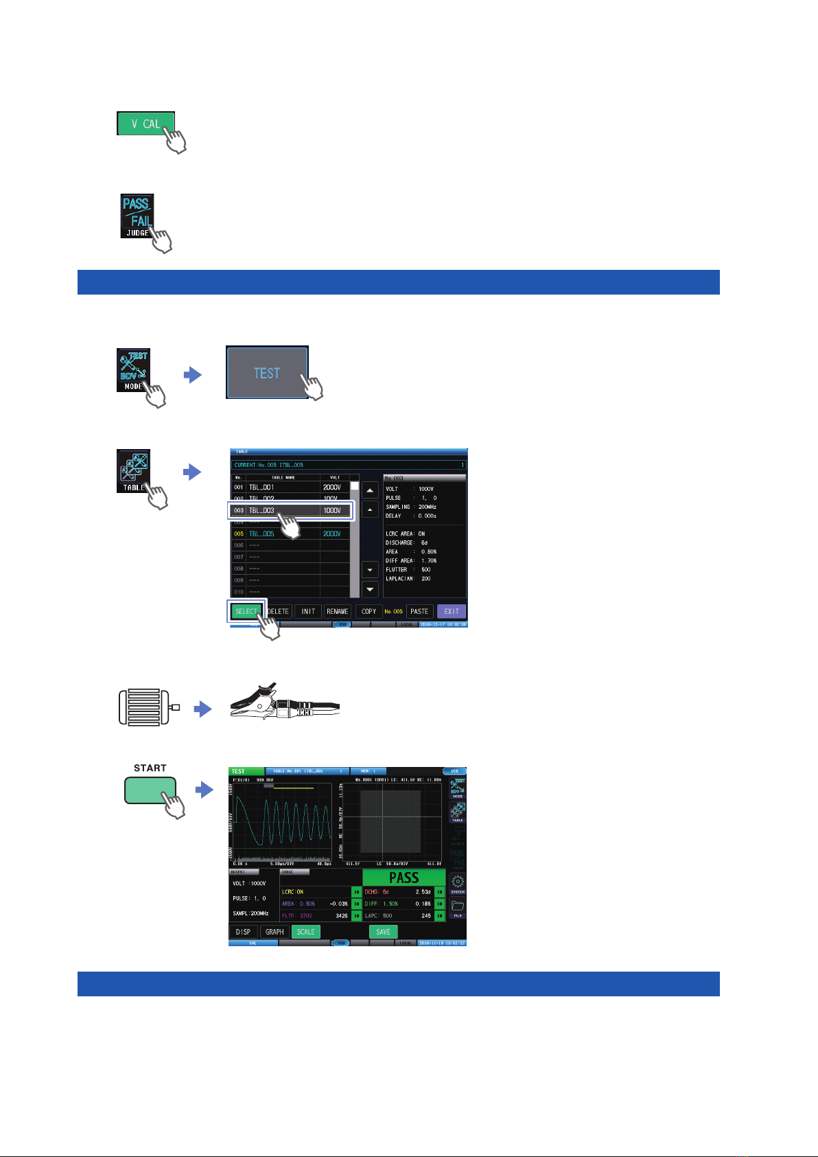
6 Implementing Tests 77
6.1 Overview ................................................77
Operations owchart in test mode ..............77
Screen conguration ..................................78
6.2 Checking Test Start and Test Results84
7 Break down voltage
test (BDV) 85
7.1 Overview ................................................85
Operations owchart in break down
voltage test mode ...................................... 85
Screen conguration ..................................86
7.2 Checking Test Start and Test Results89
7.3 Setting the Test Conditions .................90
Applied voltage settings ............................. 90
Number of applied pulses settings .............91
Setting the sampling frequency and
number of sampling data ...........................93
Setting the waveform acquisition area
automatically ............................................. 94
7.4 Setting Dielectric Break down
Judgment Conditions ...........................95
LC and RC values judgments ....................95
Discharge judgment ..................................96
Waveform surface area comparison
judgment ...................................................97
Peak voltage value uctuations .................. 98
Vibration frequency uctuations .................99
8 Other Functions 101
8.1 Interlock Function ...............................101
Unlocking the interlocks ...........................103
8.2 Key Lock Function ..............................104
Unlocking the key locks ...........................105
8.3 Double Action Function ......................106
8.4 Memory Function ................................107
Memory function settings (ON/OFF) .........108
Saving memory data................................109
Deleting memory data ............................. 110

Contents
iii
Deleting les and folders .........................186
Creating folders .......................................187
Changing the folder name and le name . . 188
Information display ..................................189
13 Specications 191
13.1 General Specications .......................191
13.2 Input Specications/Output
Specications/Measurement
Specications ......................................192
Basic specications .................................192
Accuracy specications ...........................192
13.3 Functional Specications ...................193
Test conditions settings ............................193
Set judgment conditions ..........................193
Test conditions switching functions...........195
Break down voltage test (BDV) mode ......196
Safety protection function ........................197
Other functions ........................................198
13.4 Interface Specications .....................200
External control terminal (EXT.I/O)
specications ..........................................200
Communications interface specications . . 202
USB host specications ...........................203
Test time (Reference value) .....................204
13.5 L2250 Clip Type Lead (Option) ........205
General Specications .............................205
Basic specications .................................205
13.6 L2252 Unprocessed Lead Cable
(Option) ................................................205
General Specications .............................205
Basic specications .................................205
14 Maintenance and
Service 207
14.1 Troubleshooting ..................................208
Before sending the instrument for repair .. 208
FAQ regarding external control (EXT. I/O) 212
14.2 Initializing the Instrument (Full
Reset) ...................................................213
14.3 Error Display .......................................214
14.4 Discarding the Instrument
(Removing the Lithium Battery) ........220
11 Communications
Interface 145
11.1 Overview ..............................................146
Screen display .........................................146
11.2 Specications ......................................147
RS-232C .................................................147
GP-IB ......................................................148
USB ........................................................148
LAN ........................................................148
Total ........................................................148
11.3 Mounting and Removing an
Interface ...............................................149
11.4 Interface Settings................................151
11.5 Connecting and Setting RS-232C
(Model Z3001) .....................................152
11.6 Connecting and Setting GP-IB
(Model Z3000) .....................................154
11.7 Connecting and Setting USB ............155
11.8 Setting and Connecting LAN ............157
Connection method .................................157
Setting procedure ....................................159
11.9 Remote Mode .....................................162
11.10 Communications Monitor ...................163
12 USB Host 165
12.1 Overview ..............................................165
12.2 Removing the USB Memory .............166
12.3 File Window .........................................168
12.4 Settings for Saving the Data .............169
Setting auto save.....................................169
Setting manual save ................................170
Text save items settings ...........................171
Setting the text save format .....................172
Setting the image save format .................173
Setting the name of the saved le and
its folder ..................................................174
12.5 Saving Test Results ............................176
Saving manually ......................................176
Checking the test results that have been
saved ......................................................178
12.6 Saving and Importing Test
Conditions ............................................180
Saving test conditions ..............................180
Importing test conditions ..........................182
12.7 Editing Files and Folders ...................184
Formatting USB memory .........................184
Index
11
12
13
14
15
6
7
8
9
10

Contents
iv
15 Appendix 221
15.1 Block Diagram .....................................221
15.2 Circuit Conguration ..........................222
Circuit operations during tests ..................222
Effects of cable parasitic components ...... 223
15.3 Rack Mount .........................................224
Metal tting dimensions ...........................225
Installation method ..................................227
15.4 Dimensions Diagram ..........................229
15.5 Repeat Accuracy (Reference Value) 230
Reproducibility of the voltage generated .. 230
Oscillation waveform reproducibility .........231
15.6 Max. Applicable Voltage
(Reference Value) According to
the Workpiece Inductance .................232
15.7 Voltage Switching Time (Reference
Value) ...................................................233
15.8 Waveform Differences (Typical
Values) Between Instruments ...........234
15.9 Affects on Measurements
According to the Length of the
Test Lead .............................................236
15.10 Precautions when Processing Test
Leads ....................................................237
15.11 Ver. 1.01 Compatibility Function .......239
Index 241
Warranty Certicate

1
Introduction
Introduction
Thank you for choosing the Hioki ST4030, ST4030A Impulse Winding Tester. Preserve this manual
carefully and keep it handy to make full use of this instrument for a long time. Read the separate
document “Operating Precautions” carefully before using the instrument.
Target audience
This manual has been written for use by individuals who use the product in question or who teach
others to do so.
It is assumed that the reader possesses basic electrical knowledge (equivalent to that of someone
who graduated from the electrical program at a technical high school).
Trademarks
• Windows is either registered trademarks or trademarks of Microsoft Corporation in the United
States and other countries.
• Any other products and company names are generally either trade names, registered trademarks
or trademarks of respective companies.
10
9
8
7
6
5
4
3
2
1
Appx. Ind.

2
Notations
Notations
Safety symbols
In this document, the risk seriousness and the hazard levels are classied as follows.
WARNING
Indicates a potentially hazardous situation that may result in death or serious
injury to the operator.
CAUTION Indicates a potentially hazardous situation that may result in minor injury to the
operator or damage to the instrument or malfunction.
IMPORTANT Indicates information related to the operation of the instrument or maintenance
tasks with which the operators must be fully familiar.
Indicates prohibited actions.
Indicates an action that must be performed.
Symbols afxed to the instrument
Indicates cautions and hazards. Refer to the “Usage Notes” (p. 5) and warning
messages presented at the beginning of each instruction for use of the Instruction
Manual, and included “Operating Precautions”.
Indicates that dangerous voltage may be present at this terminal.
Other Descriptions
(p. ) Indicates the location of reference information.
START
(Boldface) Indicates the names and keys on the windows in boldface.
[ ] Names of menus, dialog boxes, buttons in a dialog box, and other UI elements on the
screen are enclosed in brackets [ ].
S/s
The instrument describes the number per second of digitized analog input signals in
units of samples per second (S/s).
Example: “20 MS/s” (20 megasamples per second) means digitization of 20 × 106
times per second.
Accuracy descriptions
We dene measurement tolerances in terms of setting values with the following meanings.
Setting Indicates the value set as the output voltage, current, or other quantity.

3
Conrming Package Contents
When you receive the instrument, inspect it carefully to ensure that no damage occurred during
shipping. In particular, check the accessories, panel switches, and connectors. If damage is evident,
or if it fails to operate according to the specications, contact your authorized Hioki distributor or
reseller.
Store the packaging materials even after unpacking, because you will need them when you
transport the instrument.
Conrm that these contents are provided.
Model ST4030 or ST4030A Impulse Winding Tester
Power cord
Instruction Manual (this document)
Operating Precautions (0990A903)
Application disc (CD)
• Communication Command Instruction Manual
Communication Command Reference
Default settings table
• USB driver
The latest version can be downloaded from our website.
10
9
8
7
6
5
4
3
2
1
Appx. Ind.

4
Options (Sold separately)
The following options are available for the instrument. To purchase an option, please contact your
authorized Hioki distributor or reseller. Options are subject to change. Please check Hioki’s website
for the latest information.
Model ST9000 Discharge Detection Upgrade
(Optional when shipped from factory)
Model L2250 Clip Type Lead
(Maximum rated voltage: 3300 V AC peak)
Model L2252 Unprocessed Lead Cable
(Maximum rated voltage: 4200 V AC peak)
Model Z3000 GP-IB Interface
Model 9151-02 GP-IB Connector Cable (2 m)
Model Z3001 RS-232C Interface
Model 9637 RS-232C Cable (9pin-9pin/1.8 m)

5
Usage Notes
Usage Notes
Read the separate document “Operating Precautions” carefully before using the instrument. Follow
these precautions to ensure safe operation and to obtain the full benets of the various functions.
Installation
CAUTION
• Ventilation holes for heat radiation are provided on the rear of the instrument. Leave
sufcient space around the ventilation holes and install the instrument with the holes
unobstructed.
Installation of the instrument with the ventilation holes obstructed may cause a
malfunction of the instrument or a re.
• Do not place the instrument on an unstable surface or inclined place.Dropping or
knocking down the instrument could cause bodily injury or damage to the instrument.
Open 5 cm or longer
This instrument may cause interference if used in residential areas. Such use must be avoided
unless the user takes special measures to reduce electromagnetic emissions to prevent
interference to the reception of radio and television broadcasts.
Application disc
• Exercise care to keep the recorded side of discs free of dirt and scratches. When writing text on a
disc’s label, use a pen or marker with a soft tip.
• Keep discs inside a protective case and do not expose them to direct sunlight, high temperature,
or high humidity.
• Hioki is not liable for any issues your computer system experiences in the course of using this
disc.
Test lead
CAUTION
• Do not make small bends or repeatedly bend the cable.
As a benchmark, bending to 6x or less the cable diameter will damage the cable core
and cover, causing deterioration.
• Do not hold the cable when removing the clip from the workpiece.
• Hold the clip in your hand, and open and close gently.
Repeatedly opening and closing so that the clip springs risks damaging and causing
deterioration to the opening and closing mechanism.
10
9
8
7
6
5
4
3
2
1
Appx. Ind.

6
Usage Notes

7
1Overview
1.1 Overview
Windings (workpieces) found in motors, coils, and other components are
covered with insulation, but the insulation resistance may fall and short
circuits occur between proximate layers for some reason. The condition is
called a “layer short circuit”.
The ST4030, ST4030A Impedance Winding Tester not only compares and
judges waveform conformance through comparisons with existing response
waveforms, but also detects layer short circuits using judgment methods
that employ the rendering of response waveforms as numerical values (LC
and RC values). Further, incorporating the ST9000 Discharge Detection Upgrade (optional) into
the instrument enables highly precise detection of partial discharges that occur in the stages in
advance of a layer short circuit.
1.2 Features
High-speed and high-resolution sampling
Sampling using 200 MHz, 12 bit resolution enables the detection of minute changes in the response
waveform that hitherto could not be seen. In this way, it is possible to detect layer short circuits with
a high level of accuracy compared to before.
Numerical rendering of impulse response waveforms (LC and RC values)
The equivalence circuits for the impulse test are viewed as LCR linear equivalent circuits, and the
response waveforms are rendered numerically into LC and RC values. Rendering the response
waveforms into numerical values enables the response waveforms to be judged quantitatively.
Further, the data can be managed more easily than the waveform data.
Impulse can be tested with the rotor mounted
With the rotor and motor stator mounted, the stray capacitance between the rotor and the stator
changes depending on the rotor angle.
Changes in the stray capacitance also change the impulse response waveform, so judgments are
difcult using existing waveform comparison methods.
Numerical judgment values using LC and RC values can create PASS judgment area from the LC
and RC values distribution, and so by creating PASS judgment area using a healthy phase, it is
possible to test the impulse with the rotor mounted.
High-precision Discharge Detection Upgrade
Extracting the high-frequency discharge components of the response waveform enables highly
precise detection of partial discharges, which have hitherto been difcult to detect using utter
operations and Laplacian operations.
High waveform reproducibility
The applied voltage variation is small, so it is possible to detect defective products accurately.
Further, the instrument differences when the same workpiece is tested are small, so it is possible to
use the master workpiece data as is even if the instrument is replaced.
Reference: “15.5 Repeat Accuracy (Reference Value)” (p. 230)
Easy-to-use interfaces and an abundance of interfaces
The screen uses 8.4-inch color TFT crystals with touch panel for easy viewing and intuitive
operability. Compatible with various usage scenarios using external control (EXT. I/O), USB
memory, USB devices, and LAN. Further, RS-232C or GP-IB can be added as options.
1 Overview
1
Overview

8
Parts Names and Functions
1.3 Parts Names and Functions
1
2 3 4 5 6 7
18 17 16
811
14
13
15
Front Rear
12
11
9
3
10
Top
19 19
Bottom
212020

9
Parts Names and Functions
No. Name Function
Reference
1Display 8.4-inch color TFT liquid crystal display.
Comes with a resistant lm touch panel.
p. 10
2START button Starts measurements. p. 77
3OUTPUT lamp Shows the voltage
application status.
Red: Voltage is being applied p. 84
OFF: Standby
4USB connector Connects a USB memory. p. 165
5STOP button Stops the voltage application and suspends testing.
Also used during double actions.
p. 84,
p. 106
6PASS/FAIL lamp Shows the total judgment
result.
Green: Total judgment result PASS p. 84
Red: Total judgment result FAIL
OFF: No judgments
7Startup button Switches the instrument
ON and OFF.
OFF: Main power supply OFF p. 16
Red: Sleep mode
Green: ON mode
8Voltage output terminal Connects a test lead (optional). p. 14
9Serial number The serial number consists of 9 digits. The rst two (from the left)
indicate the year of manufacture, and the next two indicate the
month of manufacture.
Required for production control. Do not peel off the label.
p. 125
10 MAC address MAC address of the instrument. p. 125
11 Vent holes For ventilation, and to prevent the interior of the instrument from
overheating. Install so that the vent holes are not blocked.
–
12 EXT.I/O
NPN/PNP switch
Switches the programmable type of the external control terminal.
Left: NPN (current sink) Right: PNP (current source)
p. 133
13 LAN connector *1Connects a LAN cable. p. 157
14 USB connector *1Connects a USB cable. p. 155
15 External control
terminal (EXT.I/O)
Enters signals from the programmable controller and I/O boards to
control the instrument.
p. 133
16 Communications
interface*1mount
Mount a Z3000 GP-IB Interface (optional) or Z3001 RS-232C
Interface (optional).
p. 152,
p. 154
17 Power inlet Connects the provided power cord. p. 15
18 Main power supply
switch
Turns ON and OFF the main power supply to the instrument. p. 16
19 Stand Tilts the instrument to enable the screen to be viewed easily.
Make sure to fully open both the left and right stands before
installation.
–
20 Support legs When mounting the instrument to a rack*2, remove the support
legs. –
21 Handle Used to carry the instrument. –
*1: For how to use RS-232C, GP-IB, USB, and LAN, see the “Communications Commands Instruction
Manual” on the application disk.
*2: The instrument can be mounted to a rack. See “15.3 Rack Mount” (p. 224).
1
Overview

10
Screen Operations
1.4 Screen Operations
The instrument uses a touch panel for all settings and changes to the measuring conditions.
Gently touch the onscreen keys to select the items and values set for those keys.
CAUTION
Do not press the touch panel forcefully or jab it with the point of a hard object. Doing so
may cause a malfunction.
This document describes below the procedures up to displaying the various settings screens.
Example: When displaying the [SETTING] screen
(Measurement screen) [MODE] >[SETTING]
Measuring mode settings
Example: Selecting the test conditions settings mode
2
1
3
1
Tap [MODE] to display the measuring mode selection window.
2
Select the measuring mode.
Here, tap [SETTING].
3
Tap [EXIT] to return to the measurement screen.

11
Screen Operations
Moving windows
Press and hold the window title bar while dragging the window to move the window to a new
position.
Window title bar
Touch keyboard inputs
Enter text and then tap [SET] to conrm. To cancel, tap [CANCEL].
1 3 4
5 6 7
2
1Moves the cursor to the left. 5KEY TYPE Switches the keyboard type.
2Moves the cursor to the right. 6A a Switches between upper and
lower case.
3BS Deletes 1 character. 7! A Switches between symbols/
numbers, and the alphabet.
4CLR Deletes all.
1
Overview

12
Screen Operations
Screen conguration
The instrument settings windows are congured using the following stages.
MODE VOLT
PULSE
SAMPLING
DELAY
OUTPUT
DISCHARGE
AREA
DIFF AREA
FLUTTER
LAPLACIAN
JUDGE
TABLE
TEST
END
STEP
PULSE
SAMPLING
DISCHARGE
AREA
LCRC AREA
JUDGE
FILE
I/F
INFO
TEST
CLOCK
SYSTEM
NONE
BDV OUTPUT START
LCRC AREA
Measurement screen
SYSTEM
SETTING
This manual suits for next models
1
Table of contents
Other Hioki Test Equipment manuals

Hioki
Hioki MR8827 User manual

Hioki
Hioki 3805 User manual

Hioki
Hioki 3504-40 C HiTester User manual

Hioki
Hioki HiTESTER 3540 User manual

Hioki
Hioki 3417 User manual

Hioki
Hioki 3665-20 User manual

Hioki
Hioki 3561 User manual

Hioki
Hioki IR3455-01 User manual

Hioki
Hioki 3173 User manual

Hioki
Hioki 3244-60 User manual