Megger CDAX 605 User manual

User manual 1 / 28
Document ID: AI0003CE 2015-02-16
Megger Sweden AB phone: +46 8 510 195 00
Rinkebyvägen 19 email: seinfo@megger.com
182 36 Danderyd website: www.megger.com
Sweden
CDAX 605
Capacitance & Dissipation
Factor Test Set
User Manual
Copyright© 2014 by Megger. All rights reserved. Article no: ZP-AI01AE V01a
The contents of this manual are the property of Megger Sweden AB. No part of this work may be reproduced or transmitted in any form
or by any means, except as permitted in written license agreement with Megger Sweden AB. Megger Sweden AB has made every
reasonable attempt to ensure the completeness and accuracy of this document. However, the information contained in this manual is
subject to change without notice, and does not represent a commitment on the part of Megger Sweden AB. Any attached hardware
schematics and technical descriptions, or software listings that disclose source code, are for informational purposes only. Reproduction
in whole or in part to create working hardware or software for other than Megger Sweden AB products is strictly prohibited, except as
permitted by written license agreement with Megger Sweden AB.
TRADEMARK NOTICES
Megger® and Programma® are trademarks registered in the U.S. and other countries. All other brand and product names mentioned in
this document are trademarks or registered trademarks of their respective companies. Megger Sweden AB is certified according to ISO
9001 and 14001.

User manual 2 / 28
Document ID: AI0003CE 2015-02-16
Megger Sweden AB phone: +46 8 510 195 00
Rinkebyvägen 19 email: seinfo@megger.com
182 36 Danderyd website: www.megger.com
Sweden
Content
1Overview................................................................................................................................................... 3
1.1 General .............................................................................................................................................. 3
1.2 Measurement principle ...................................................................................................................... 3
2Specification.............................................................................................................................................. 3
3Safety......................................................................................................................................................... 5
3.1 General .............................................................................................................................................. 5
3.2 Instrument symbols ........................................................................................................................... 5
3.3 Warning and Caution Notices............................................................................................................ 6
3.3.1 Warning..................................................................................................................................... 6
3.3.2 Caution ...................................................................................................................................... 6
3.4 General safety information ................................................................................................................ 6
3.5 Instrument safety ............................................................................................................................... 7
4Maintenance .............................................................................................................................................. 8
5Warranty.................................................................................................................................................... 8
5.1 Receiving Instructions....................................................................................................................... 8
5.2 Warranty............................................................................................................................................ 8
5.3 Warranty repair.................................................................................................................................. 8
6Control, indicators and connectors............................................................................................................ 9
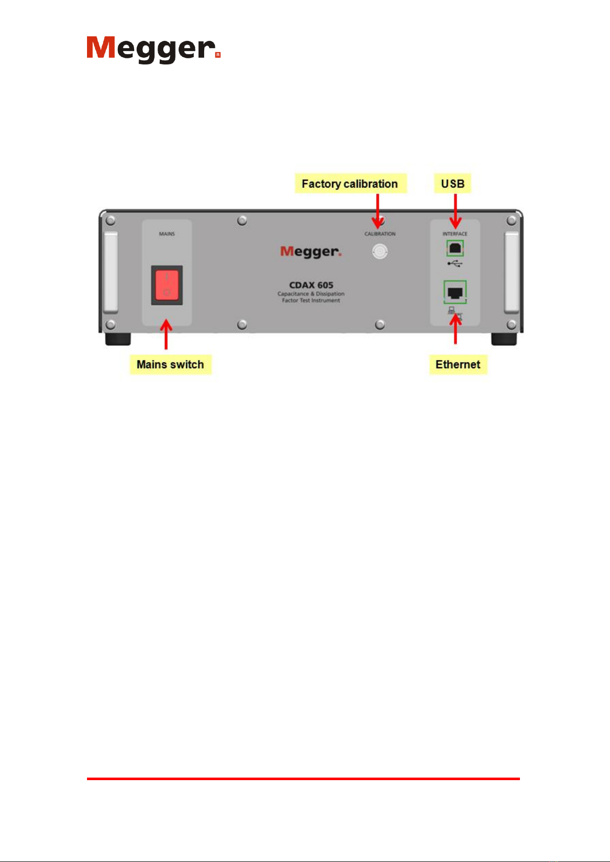
6.1 Front panel......................................................................................................................................... 9
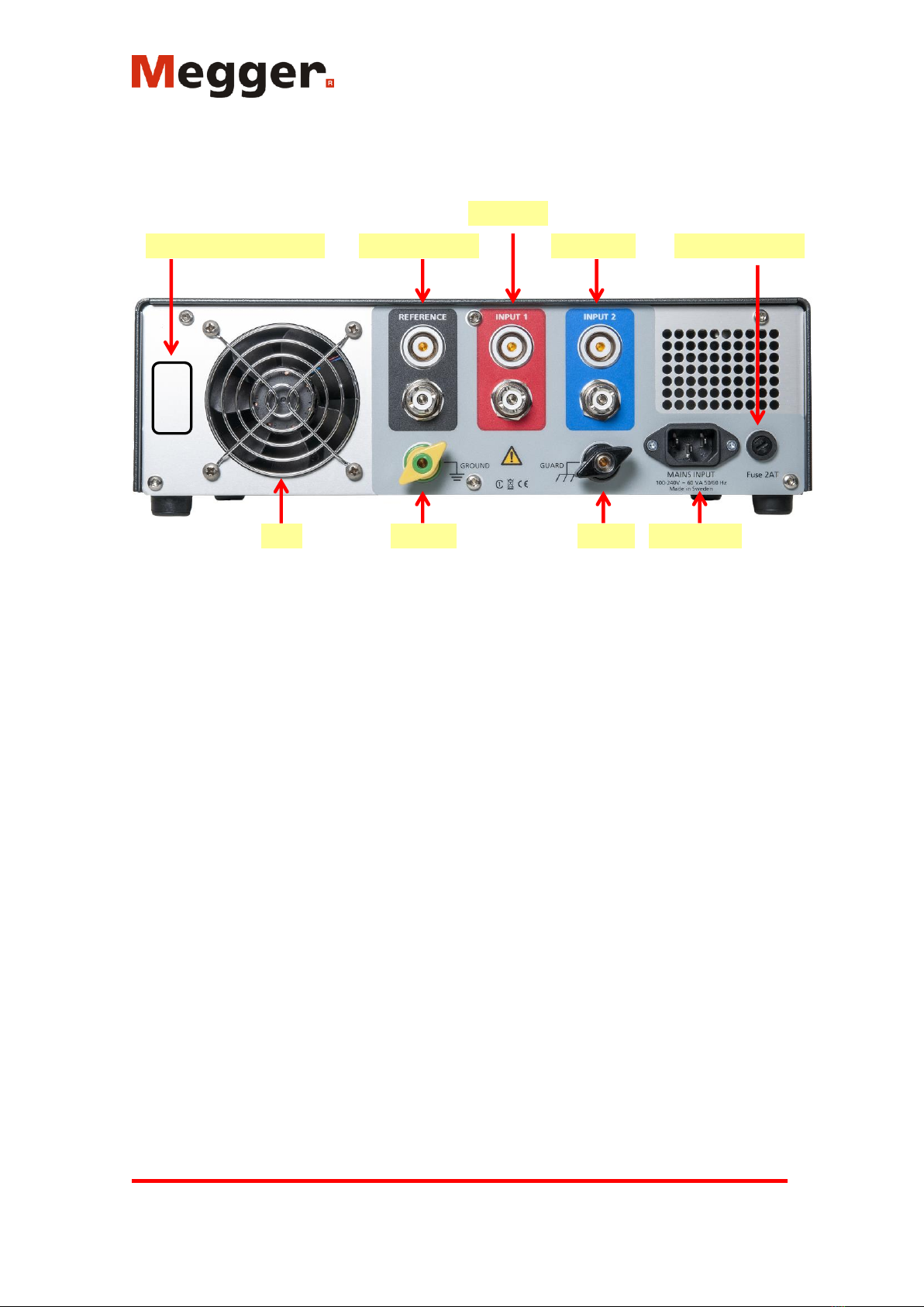
6.2 Back panel ....................................................................................................................................... 10
7Software Installation................................................................................................................................ 11
8CDAX605 Control .................................................................................................................................. 11
8.1 Connect............................................................................................................................................ 11
8.2 Control tab....................................................................................................................................... 12
8.3 Settings tab ...................................................................................................................................... 14
9Calibration............................................................................................................................................... 16
9.1 Warm-up.......................................................................................................................................... 16
9.2 Calibration procedure ...................................................................................................................... 16
9.2.1 Calibration............................................................................................................................... 17
9.2.2 Balancing................................................................................................................................. 17
10 Operating instructions ......................................................................................................................... 17
10.1 Standard test circuits........................................................................................................................ 17
10.1.1 Ungrounded Specimen Test (UST) with grounded HV Supply............................................... 17
10.1.2 Ratio transformer with grounded HV supply........................................................................... 20
10.1.3 Grounded Specimen Test (GST) with floating HV Supply ..................................................... 21
10.2 Measurements with Test Current greater than 5A (with external current transformer)................... 22
10.2.1 General information on Range Extension................................................................................ 22
10.2.2 Errors caused by an external CT.............................................................................................. 22
11 Stored data and reporting..................................................................................................................... 23
12 User fields............................................................................................................................................ 23
12.1 Editing user fields............................................................................................................................ 24
12.1.1 Description of buttons ............................................................................................................. 24
12.1.2 User field parameters............................................................................................................... 24
12.1.3 Entering a formula................................................................................................................... 26
12.1.4 Example –Creating a user field showing correction factor..................................................... 27
12.2 The Results Window ....................................................................................................................... 27

User manual 3 / 28
Document ID: AI0003CE 2015-02-16
Megger Sweden AB phone: +46 8 510 195 00
Rinkebyvägen 19 email: seinfo@megger.com
182 36 Danderyd website: www.megger.com
Sweden
1 Overview
1.1 General
CDAX605 is a measurement instrument that is used with a separate AC power source and a
reference capacitor to form a complete measurement setup. It is a precision instrument using direct
measurement for fast data acquisition in combination with an internal balancing circuit that secures
a very high accuracy in line with traditional ratio-arm bridges. CDAX605 is designed for
laboratory, production line or field testing of electrical equipment insulation and insulating
materials as well as e.g. calibration of CCVTs and other ratio devices. A test set with unique high
accuracy for the most demanding applications.
Testing can be performed at almost any voltage level pending on the rating of the equipment, the
power source and the capacitor. The unit has full accuracy from current as low as 15 µA and will
accept a test current up to 5 A from the insulation under test. The test current may be increased by
use of an external current transformer. CDAX605 is designed to be able to directly replace the
(obsolete) Multi-Amp CB-605 High-voltage capacitance and dissipation factor bridge.
Traditional bridge methods can only measure and compare capacitive currents and since calibrated
reference capacitors are typically available in the 100 to 1000 pF range, precision measurements on
e.g. CCVTs and other devices with a high ratio may be difficult to perform. With the new
technology in CDAX605, the input voltage to the device can be measured with a traditional
reference capacitor while the secondary low voltage can be measured either with a second
reference capacitor or with a reference resistor that is designed to give appropriate measurement
current. Nor reference capacitors or resistors are included in a standard delivery.
1.2 Measurement principle
CDAX measuring system is based on the so called “double vector-meter method”. Measurement of
the current IN through a known standard capacitor CN and current IX through an unknown test object
CX. Both branches are energized by an external HV AC power source (UTest) and both currents are
measured by high accuracy ammeters. Based on the data coming from the known standard
capacitor all desired measuring values can be determined directly without any manual interaction.
The accuracy of the unit is based on “ammeter similarity”. If the ammeters are identically in all
aspects, the inaccuracy of the system is zero. To ensure similarity during various operating
conditions, an internal balancing circuitry can be activated to run automatically or on command.
The results from the balancing check are if necessary used to adjust range gain settings to ensure
that the two channels are similar over the measurement range.
2 Specification
The CDAX is intended for indoor use but can also be used outdoors but not in wet conditions (e.g.
rain or high humidity, see Relative humidity below for more details). As accuracy of capacitance
and ratio (not phase and dissipation factor) is affected by temperature, a stable environment
regarding temperature is essential for accurate readings. To achieve maximum accuracy, turn on
the unit and allow the unit to adjust to the ambient temperature for at least 30 minutes before first
balancing. After balancing, specified accuracy will be achieved.

User manual 4 / 28
Document ID: AI0003CE 2015-02-16
Megger Sweden AB phone: +46 8 510 195 00
Rinkebyvägen 19 email: seinfo@megger.com
182 36 Danderyd website: www.megger.com
Sweden
Parameter
Specification
Comment
General
Dimensions
335 x 300 x 99 mm
(17.7” x 16.1” x 6.3”)
Instrument
Dimensions
520 x 430 x 220 mm
(20.5” x 17.0” x 8.7”)
Transport case
Weight
4.4 kg (9.7 lbs)
Instrument only
Mains voltage
100 - 240 V AC, 50/60 Hz
± 10 %
Power
consumption
60 VA (max)
Measurement
channels
2
2 physical ammeters
Measurement inputs
4
Reference, Input 1 (red), Input 2 (blue)
and Ground
Test Modes
7
UST-R, UST-B, UST-RB, GST-GND,
GSTg-R, GSTg-B, GSTg-RB
Test frequency
5 - 500 Hz
Measurement range
Capacitance
> 0.01 pF
Max capacitance is a function of
applied voltage
Inductance, Lp
< 1 MH
Min inductance is a function of applied
voltage
Dissipation factor
0 - 100
0 - 10 within specified accuracy
Voltage
Unlimited
Pending reference capacitor value
only
Current
15 µA - 5 A
Can be increased by using an external
current transformer.
Phase
0 - 360°/0-2π mrad
Accuracy (*
Capacitance
± 0.02%
At reference and test currents <
300mA
± 0.1%
At reference and test currents 300-
1000 mA
Inductance
± 0.1 %
Voltage/current
± 0.5% of reading
Absolute voltage/current reading
Dissipation factor
± (0.05% of reading + 2x10-
5)
At reference and test currents <
300mA
± (0.05% of reading + 5x10-
5)
At reference and test currents 300-
1000 mA
Phase
± 0.02 mrad
At reference and test currents <
300mA
± 0.05 mrad
At reference and test currents 300-
1000 mA
Voltage/current
± 0.5% of reading
Absolute voltage/current reading
Max resolution
Capacitance
0.001 pF
Inductance
0.1 mH
Dissipation factor
1x10⁻⁶
Phase
1x10⁻⁶ Rad
Measurement time
Selectable, default 5 s
Warm-up time
30 min
Temperature range
Operating
-20 - 55°C (-4 - 131°F)
Storage
-40 - 70°C (-40 - 158°F)
Humidity
Operating
0 to 90% non-condensing
Calibration
Absolute calibration and
manual or automatic
amplitude balancing
Recommended interval for absolute
calibration is 1 year

User manual 5 / 28
Document ID: AI0003CE 2015-02-16
Megger Sweden AB phone: +46 8 510 195 00
Rinkebyvägen 19 email: seinfo@megger.com
182 36 Danderyd website: www.megger.com
Sweden
SW
CDAX605 Control
Reference data entry
Capacitance/inductance
Resistance
Dissipation factor
Phase (Rad or min)
Ratio measurements
Data log/storage
Data export (cut & paste)
Optional LabView and C# interface
PC requirements
Pentium 500 MHz/512 Mb or
better. Windows XP, Vista, 7
or 8
Communication
Ethernet (recommended) or
USB
High quality shielded Ethernet cable or
USB cable with ferrite choke
CE marking
LVD: IEC 61010
EMC: IEC 61326
*) Accuracy values are valid under the following conditions:
Internal balancing performed after minimum 30 min warm-up
Test generator frequency 50/60Hz
THD of power source <10%
UST measurement
Measurement (averaging) time 5 s
Ambient temperature 23° C ± 5°
Magnetic field at measurement frequency < 5 μT
3 Safety
3.1 General
IMPORTANT
Read and comply with the following instructions.
Always comply with local safety regulations.
3.2 Instrument symbols
Caution, refer to the accompanying documents, e.g. User Manual.
Protective conductor terminal.
Guard terminal used for GST measurements only. The terminal must be at
ground potential and the symbol indicates that a hazardous live voltage must
not be connected to the guard terminal.
WEEE, Waste Electrical and Electronic Equipment. Please utilize your local
WEEE collection facilities in the disposition of this product and otherwise
observe all applicable requirements.

User manual 6 / 28
Document ID: AI0003CE 2015-02-16
Megger Sweden AB phone: +46 8 510 195 00
Rinkebyvägen 19 email: seinfo@megger.com
182 36 Danderyd website: www.megger.com
Sweden
CE marking indicates that the product fulfills all applicable EU requirements.
Marking indicates that the product fulfills the requirements in stated in
CAN/CSA C22.2, No. 61010-1, 2nd edition including Amendment 1.
3.3 Warning and Caution Notices
Warning and caution notices are used throughout this manual where applicable and should be
strictly observed. These notices appear in the format shown below and are defined as follows:
3.3.1 Warning
Warning, as used in this manual, is defined as a condition or practice which could result in personal
injury or loss of life.
3.3.2 Caution
Caution, as used in this manual, is defined as a condition or practice which could result in damage
to or destruction of the equipment or apparatus under test.
3.4 General safety information
The test set and the specimen to which it is connected are a possible source of high-voltage
electrical energy and all persons making or assisting in tests must use all safety practice precautions
to prevent contact with energized parts of the test equipment and related circuits.
Persons actually engaged in the test must stand clear of all parts of the complete high-voltage
circuit, including all connections, unless the test set is de-energized and all parts of the test circuit
are grounded. Persons not directly involved with the work must be kept away from test activities by
suitable barriers, barricades, or warnings.
Treat all terminals of high-voltage power equipment as a potential electric shock hazard. There is
always the potential of voltages being induced at these terminals because of proximity to energized
high-voltage lines or equipment.
Always use a safety ground stick to ground the high-voltage conductor. Always disconnect test
leads from power equipment before attempting to disconnect them from the test set. The ground
connection must be the first made and the last removed. Any interruption of the grounding
connection can create an electric shock hazard.
It is not possible to eliminate all potential hazards from, and in using, electrical test equipment. For
this reason, every effort has been made to point out in this instruction manual the proper procedures
and precautions to be followed by the user in operating this equipment and to mark the equipment
itself with precautionary warnings where appropriate. It is not possible to foresee every hazard
which may occur in the various applications of this equipment. It is therefore essential that the user,
in addition to following the safety rules in this manual, also carefully consider all safety aspects of
the test before proceeding.
High-voltage discharges and other sources of strong electric or magnetic fields may interfere with
the proper functioning of heart pacemakers. Persons with heart pacemakers should obtain expert
C
1

User manual 7 / 28
Document ID: AI0003CE 2015-02-16
Megger Sweden AB phone: +46 8 510 195 00
Rinkebyvägen 19 email: seinfo@megger.com
182 36 Danderyd website: www.megger.com
Sweden
advice on the possible risks before operating this equipment or being close to the equipment during
operation.
3.5 Instrument safety
This instrument operates from a single-phase power source. It has a three-wire power cord and
requires a two-pole, three-terminal, live, neutral, and ground type connector. The voltage of the
power source must be within the following rated operating voltage: 100-240 V ± 10 %, 50/60 Hz.
Before making connection to the power source, determine that the instrument rating matches the
voltage of the power source and has a suitable two-pole, three-terminal grounding connector.
The power input plug must be inserted only into a mating receptacle with a ground contact. Do not
bypass the grounding connection. Any interruption of the grounding connection can create an
electric shock hazard. Determine that the receptacle is properly wired before inserting the plug.
The test voltage which is reported by the instrument depends on the entered reference capacitance
value. Also, during self-calibration, the instrument will not be indicating if high voltage is present.
Never use the reported high voltage reading as an indicator whether high voltage is present. Always
make sure that other safeguards exist so that the maximum allowable voltage cannot be exceeded
due to incorrect readings from the instrument.
All persons making or assisting in tests must use all practical safety precautions to prevent contact
with energized parts of the test equipment and related circuits. Also follow all local and company
safety requirements. Persons actually engaged in the test must stand clear of all parts of the
complete high- voltage circuit, including all connections, unless the test set is de-energized and all
parts of the test circuit are grounded. Persons not directly involved with the work must be kept
away from test activities by suitable barriers, barricades, or warnings.
Safety is the responsibility of the user.
Misuse of this high-voltage equipment can be extremely dangerous.
The purpose of this equipment is limited to use as described in this manual. Do not use the
equipment or its accessories with any device other than specifically described.
Make sure that the instrument is properly grounded, both through its AC power cord and
through the test ground connector.
Never connect the test set to energized equipment.
Before making any connections, make sure that the high voltage generator is de-energized
and that all parts of the test circuit are properly grounded.
Always disconnect test leads from test specimen before attempting to disconnect them at
the test set.
The ground connection on the test set must be the first made and the last removed. Any
interruption of the grounding connection can create an electric shock hazard.
Operation is prohibited in rain or snow.
Do not use the test set in an explosive atmosphere.
A qualified operator should be in attendance at all times while the test equipment is in
operation.
Observe all safety warnings marked on the equipment.
Corrective maintenance must only be performed by qualified personnel who are familiar
with the design and operation of the test set and the hazards involved.
Refer to IEEE 510 - 1983, “IEEE Recommended Practices for Safety in High-Voltage and
High-Power Testing,” for information.

User manual 8 / 28
Document ID: AI0003CE 2015-02-16
Megger Sweden AB phone: +46 8 510 195 00
Rinkebyvägen 19 email: seinfo@megger.com
182 36 Danderyd website: www.megger.com
Sweden
4 Maintenance
DISCONNECT the MAINS plug before any cleaning or maintenance.
Maintenance should be performed only by qualified personell familiar with the hazards
involved with high-voltage test equipment.
Read and understand Safety in the User Manual before performing any service.
Routine maintenance is all that is required for these test sets. The cables and connector
panel should be inspected frequently to be sure all connections are tight and all ground
connections intact.
The appearance of the test set can be maintained by occasional cleaning of the case, panel
and cable assemblies. The outside of the carrying case can be cleaned with detergent and
water. Dry with a clean, dry cloth. The control panel can be cleaned with a cloth dampened
with detergent and water. Do not allow water to penetrate panel holes, because damage to
components on the underside may result. A household all-purpose spray cleaner can be
used to clean the panel. Polish with a soft, dry cloth, taking care not to scratch the display
screen cover. The cables and mating panel receptacles can be cleaned with isopropyl or
denatured alcohol applied with a clean cloth.
5 Warranty
5.1 Receiving Instructions
Check the equipment received against the packing list to ensure that all materials are
present. Notify Megger of any shortage.
Examine the instrument for damage received in transit. If damage is discovered, file a
claim with the carrier at once and notify Megger, giving a detailed description of the
damage.
This instrument has been thoroughly tested and inspected to meet rigid specifications
before being shipped. It is ready for use when set up as indicated in this user manual.
5.2 Warranty
Products supplied by Megger are warranted against defects in material and workmanship
for a period of one year following shipment.
Our liability is specifically limited to replacing or repairing, at our option, defective
equipment.
This warranty does not include batteries, lamps or other expendable items, where the
original manufacturer’s warranty shall apply.
We make no other warranty. The warranty is void in the event of negligence abuse (failure
to follow recommended operating procedures) or failure by the customer to perform
specific maintenance as indicated in this manual.
5.3 Warranty repair
Equipment returned to the factory for repair must be shipped prepaid and insured.
Contact your Megger representative for instructions and a return authorization (RA)
number.
Please indicate all pertinent information, including problem symptoms.
Also specify the serial number and the catalog number of the unit.

User manual 9 / 28
Document ID: AI0003CE 2015-02-16
Megger Sweden AB phone: +46 8 510 195 00
Rinkebyvägen 19 email: seinfo@megger.com
182 36 Danderyd website: www.megger.com
Sweden
6 Control, indicators and connectors
6.1 Front panel
On/off Mains switch, single pole switch, On = right, Off = left, see symbol on panel
Calibration Used for factory calibration only
USB/B Controlling the CDAX from a PC using USB (USB cable with ferrite choke)
Ethernet Controlling the CDAX from a PC or using Ethernet (shielded Ethernet cable)
Ethernet communication is recommended due to better protection against high
interference.

User manual 10 / 28
Document ID: AI0003CE 2015-02-16
Megger Sweden AB phone: +46 8 510 195 00
Rinkebyvägen 19 email: seinfo@megger.com
182 36 Danderyd website: www.megger.com
Sweden
6.2 Back panel
Guard
Reference input
Red input
Blue input
Ground Mains input
Fuse 2 slow blow
Fan
S/N
Serial & art number label
Label Article number (AI-19070) and serial number (YYXxxxx)
Reference Input for reference (normal) capacitor, Lemo and UHF connectors in parallel
Input 1 Red input, Lemo and UHF connectors in parallel
Input 2 Blue input, Lemo and UHF connectors in parallel
Input adapter Three UHF to BNC adapters are delivered as a standard accessory making it
possible to use BNC cables instead of UHF.
Mains input 100-240 V AC, 50/60 Hz, max 60 VA, disconnecting device
Fuse 2AT slow blow 5x20 mm fuse, Littlefuse or similar
Ground Connector for attaching CDAX to protective ground
Guard Connector for attaching CDAX to guard when doing GST measurements
A jumper is delivered with the unit between Ground and Guard.
Note: If a jumper is connected between ground and guard, it must be removed
when performing GST measurements!

User manual 11 / 28
Document ID: AI0003CE 2015-02-16
Megger Sweden AB phone: +46 8 510 195 00
Rinkebyvägen 19 email: seinfo@megger.com
182 36 Danderyd website: www.megger.com
Sweden
7 Software Installation
To start installing the software, insert the USB memory stick and run the program CDAX 605
install program. Follow instructions on the screen.
8 CDAX605 Control
8.1 Connect
Connect the PC to CDAX using the Ethernet cable. When you start the CDAX605 software it will
try to connect to a CDAX605 unit. When the dialog is displayed you can select which CDAX605
unit you want to connect to. You can either select it in the list of found instruments or enter the IP
address. You may also select to always try to connect to that specific unit.
It is possible to communicate between CDAX and the PC using USB, but this is mainly used while
updating software in an office environment.

User manual 12 / 28
Document ID: AI0003CE 2015-02-16
Megger Sweden AB phone: +46 8 510 195 00
Rinkebyvägen 19 email: seinfo@megger.com
182 36 Danderyd website: www.megger.com
Sweden
8.2 Control tab
The main screen tab is the tab shown at start-up and the screen used for measuring.
By activating one or several buttons/measurement channels 1, 2, 3 the instrument is put in the
different standard test modes. CDAX supports the following test modes:
UST: Ungrounded Specimen Testing
Test mode
Measure
Ground
Guard
UST-R
UST-B
UST-RB
Red
Blue
Red and Blue
Blue
Red
---
---
---
---
GST: Grounded Specimen Testing
Test mode
Measure
Ground
Guard
GST-GND
GSTg-R
GSTg-B
GSTg-RB
Ground
Ground
Ground
Ground
Red and Blue
Blue
Red
---
---
Red
Blue
Red and Blue
As an example, activating all channels puts the instrument in GST-GND mode.

User manual 13 / 28
Document ID: AI0003CE 2015-02-16
Megger Sweden AB phone: +46 8 510 195 00
Rinkebyvägen 19 email: seinfo@megger.com
182 36 Danderyd website: www.megger.com
Sweden
Continuous measurements are shown in the “Results” part
The Oscilloscope displays the signal (white) proportional to current in reference (Cn) arm and the
signal (red) proportional to the measured current (red), e.g. in Cx1-arm. Since the “ampere-meters”
have 4 gain steps, the proportional constant varies in steps increasing the currents. The oscilloscope
time base is automatic
To start an individual measurement press “Measure”
To manually start a balancing check press “Balancing”

User manual 14 / 28
Document ID: AI0003CE 2015-02-16
Megger Sweden AB phone: +46 8 510 195 00
Rinkebyvägen 19 email: seinfo@megger.com
182 36 Danderyd website: www.megger.com
Sweden
8.3 Settings tab
Clicking on the reference brings up the reference dialog where you can change the type and value;
Typically, a zero dissipation factor is used for compressed gas filled reference capacitor, but it is
possible to add a dissipation factor of the reference capacitor if e.g. a reference polystyrene
capacitor is used. Note that accuracy of measurement, and possible temperature dependence,
depends very much of type of reference and most accurate results are achieved by use of standard
compressed gas capacitor.

User manual 15 / 28
Document ID: AI0003CE 2015-02-16
Megger Sweden AB phone: +46 8 510 195 00
Rinkebyvägen 19 email: seinfo@megger.com
182 36 Danderyd website: www.megger.com
Sweden
Clicking on one of the test specimens makes it possible to change its settings.
Clicking one of the squares on the red/blue connection “leads” brings up the options for using an
external current transformer.
Synchronization mode:
CDAX measures fundamental frequency of reference, Cn, current and sample current using a filter
with a bandwidth of ±6 Hz/s of integration. E.g. using 5 s of integration, the bandwidth is ±1.2 Hz.
CDAX supports three synchronization modes that are selected by press the “Sync. Mode…-
button”.

User manual 16 / 28
Document ID: AI0003CE 2015-02-16
Megger Sweden AB phone: +46 8 510 195 00
Rinkebyvägen 19 email: seinfo@megger.com
182 36 Danderyd website: www.megger.com
Sweden
AC line means that the mains frequency of the CDAX unit is measured continuously and
the frequency is used as synchronization frequency. This is the best choice when the unit is
used with a test generator supplied form the AC mains.
Reference input means that the reference input signal is measured and used for
synchronization. You need to set an approximate synchronization frequency (e.g. 50, 60 or
400 Hz). Note: Reference current must be > 30 µA for synchronization
No synchronization means that the CDAX system measures using set frequency for
synchronization regardless of AC line frequency or applied frequency on reference input.
You must set a frequency near the actual frequency.
In most measurement setups, CDAX is measuring a capacitive object and using a standard
capacitor on the reference input. In those situations, “No synchronization” works well and gives
fast updates of displayed results.
However when measuring a mixed setup, e.g. ratio with a standard capacitor as reference and a
reference resistor on secondary, the frequency is of utmost importance for accuracy in ratio values
and synchronized mode must be used.
9 Calibration
9.1 Warm-up
To achieve maximum accuracy, turn on the unit and allow the unit to adjust to the ambient
temperature for at least 30 minutes and a balancing is performed.
9.2 Calibration procedure
System calibration is made up of two routines: Calibration, typically performed every year, and
manual or automatic amplitude balancing, performed in the field after warm-up and at customer
defined intervals.
The calibration for amplitude and phase should be performed at the recommended calibration
interval of the system, i.e. every year. Amplitude balancing is performed when asked for or
automatically by the instrument at intervals specified by the user. During amplitude balancing the

User manual 17 / 28
Document ID: AI0003CE 2015-02-16
Megger Sweden AB phone: +46 8 510 195 00
Rinkebyvägen 19 email: seinfo@megger.com
182 36 Danderyd website: www.megger.com
Sweden
instrument checks that (and if necessary adjust for) the two measuring channels, reference and
specimen input, are similar.
The balancing procedure is controlling the accuracy of relational measurements such as capacitance
and ratio. Calibration is confirming phase and dissipation factor measurements as well as absolute
readings of the two measurement channels, i.e. voltage and current readings.
9.2.1 Calibration
Calibration is performed using the MIX utility software. The required hardware for performing a
complete absolute calibration is, apart from the system itself, a calibrated Digital Multi Meter
(DMM) with adequate accuracy. The procedure is fully documented in the MIX utility software. A
few points are however worthwhile to note:
It is convenient to store the calibration data also outside of the instrument for future
reference.
For highest accuracy, make sure that the instrument is calibrated in its intended operating
conditions.
As pointed out in the MIX software: When measuring the resistance of the internal
reference resistor –Make sure that the excitation current of the DMM is not greater than
100 µA. This is checked referring to the DMM user manual.
9.2.2 Balancing
Amplitude balancing is by default performed automatically after 30 minutes of warm-up (this can
be cancelled if e.g. the instrument is just re-started from a previous session and already warmed-
up). After the initial balancing, the instrument will re-check the channels manually when called for
or automatically at specified intervals. This is configurable in the CDAX Control settings tab. The
balancing parameters are stored in the instrument. It is also possible to configure the instrument to
defer automatic balancing if the high voltage is measured to be active.
10 Operating instructions
10.1 Standard test circuits
In this chapter the standard measuring setups are explained. The circuits are also applicable for
inductances.
10.1.1 Ungrounded Specimen Test (UST) with grounded HV Supply
This test mode is the most common situation when measuring capacitance and dissipation factor.
Various ungrounded capacitances can be measured using this mode, providing that the maximum
test current of the measuring instrument is not exceeded. When measuring power transformers and
HV voltage and current transformers, this configuration determines the capacitance and dissipation
factor between the various winding groups.
In this mode the highest measurement accuracy is reached.

User manual 18 / 28
Document ID: AI0003CE 2015-02-16
Megger Sweden AB phone: +46 8 510 195 00
Rinkebyvägen 19 email: seinfo@megger.com
182 36 Danderyd website: www.megger.com
Sweden
Figure 1. Capacitance measurement setup
10.1.1.1 Step-by-step instructions
Before connecting the instrument, make sure that the high voltage generator is de-
energized and that all parts of the test circuit are properly grounded.
Referring to Figure 1, connect the instrument to:
oTest ground, i.e. same grounding point as the test specimen.
oA suitable AC power source.
oThe reference capacitor, Cn.
oThe test specimen.
Set up the computer:
oConnect the computer to the CDAX605 using a shielded Ethernet cable (or USB
cable with ferrite choke).
oRun CDAX605 Control and connect to the instrument.
oIn the Settings tab, set the value of the reference capacitor (see figure below) and
also configure the test specimen (press red, and/or blue, green).

User manual 19 / 28
Document ID: AI0003CE 2015-02-16
Megger Sweden AB phone: +46 8 510 195 00
Rinkebyvägen 19 email: seinfo@megger.com
182 36 Danderyd website: www.megger.com
Sweden
Return to Control tab
Commence the measurement procedure:
oRemove the high voltage side safety grounding.
oCarefully raise test voltage somewhat and check that the voltage reported by the
instrument is as expected. Note that incorrect input of the reference capacitance
value will lead to incorrectly reported voltage level, which may lead to excessive
voltage levels.
oCheck that the continuously updated measurement results are as expected.
oRaise voltage to the specified test level.
oPress MEASURE. Results will be displayed

User manual 20 / 28
Document ID: AI0003CE 2015-02-16
Megger Sweden AB phone: +46 8 510 195 00
Rinkebyvägen 19 email: seinfo@megger.com
182 36 Danderyd website: www.megger.com
Sweden
Save, results will be stored in “results log”. If “cancel”, results are not stored
oPerform additional measurements as required by pressing MEASURE again.
oLower the test voltage and turn of the generator.
Disconnect the instrument in reverse order as during connection, i.e. de-energize and
ground all parts of the circuit before disconnecting.
10.1.2 Ratio transformer with grounded HV supply
Calibrate/confirm the two reference components Cn and Cn1 (labeled C1 in Figure 1) by
connecting them as in Figure 1 (section 10.1.1) and following the corresponding instruction. Note
that the voltage handling capability of Cn1 might be limited.
Without reconnecting:
oSet up the software for ratio measurement, entering the calibrated values for Cn or
Rn.
oMeasure the ratio and verify that it is exactly unity with zero phase shift.
Table of contents
Other Megger Test Equipment manuals

Megger
Megger MGFL 100 User manual

Megger
Megger ODEN AT User manual

Megger
Megger Programma Sverker 750 User manual

Megger
Megger BM5200 User manual

Megger
Megger HPG AC Series User manual

Megger
Megger BMM500 Series User manual

Megger
Megger MIT510/2 User manual

Megger
Megger BM15 User manual

Megger
Megger OTS100AF User manual

Megger
Megger BM5200 Quick start guide

Megger
Megger DET2/3 User manual

Megger
Megger MIT200 Series User manual

Megger
Megger BM25 User manual

Megger
Megger TTR25 User manual

Megger
Megger MFT1500 Series User manual

Megger
Megger TTR 550503 User manual

Megger
Megger MFT1800 series User manual

Megger
Megger BITE2 User manual

Megger
Megger PAT120 User manual

Megger
Megger BM80/2 Series User manual