KALATEL KTD-400 User manual

KTD-400
Controller Keypad
Installation and Operation
Manual

2 1034790D / January 2001
KTD-400 Controller Keypad Installation and Operation Manual
© 2000, Kalatel, a division of Interlogix, Inc.
All Rights Reserved.
ANY KALATEL SO TWARE SUPPLIED WITH KALATEL PRODUCTS IS PROPRIETARY AND
URNISHED UNDER LICENSE AND MAY BE USED OR COPIED ONLY IN ACCORDANCE
WITH THE TERMS O SUCH LICENSE.
This document contains proprietary information that is protected by copyright.
No part of this document may be reproduced or transmitted in any form or by any means without
the prior written permission of Kalatel, a division of Interlogix, Inc.
The information contained in this document is subject to change without notice. Kalatel, in keeping
pace with technological advances, is a company of product innovation. Therefore, it is difficult to
ensure that all information provided is entirely accurate and up-to-date. Kalatel accepts no
responsibility for inaccuracies or omissions and specifically disclaims any liabilities, losses, or
risks, personal or otherwise, incurred as a consequence, directly or indirectly, of the use or
application of any of the contents of this document.
For te hni al support before and after installation, all 800-469-1676.
Kalatel o ers 24-hr technical support 7 days a week.
Call: Te h Support 800-469-1676 (6 a.m. – 5 p.m. PST Monday through riday)
Te h Support 541-740-3589 (all other times)
Main 800-343-3358 or 541-754-9133
ax: Te h Support 541-752-9096 (available 24 hr a day)
Main 541-754-7162
Web: www.kalatel.com
1034790D / January 2001

3
1034790D / January 2001
KTD-400 Controller Keypad Installation and Operation Manual
Contents
Introdu tion ........................................................................................................................ 5
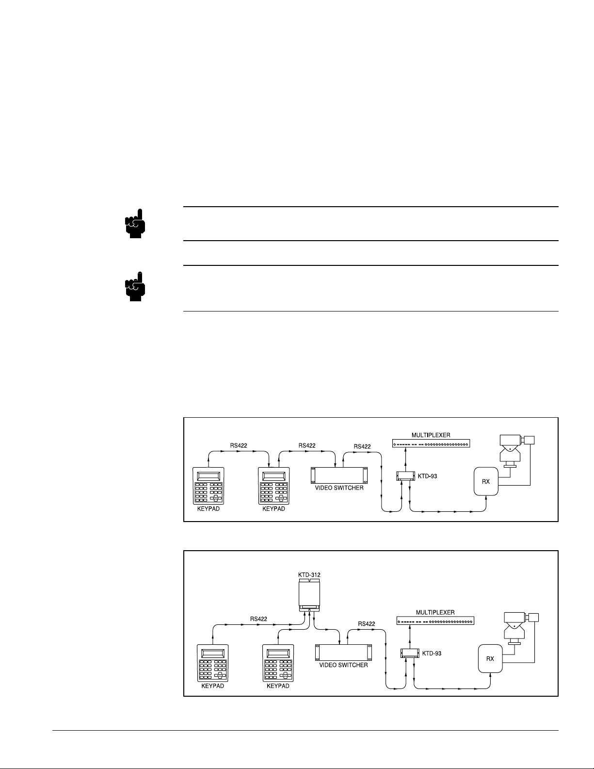
Controller Keypad Placement .............................................................................................................5
Installation .......................................................................................................................... 7
KTD-400 & KTD-300R ........................................................................................................................7
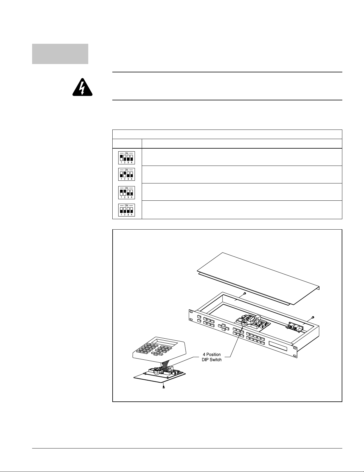
Setting the DIP Switch ..................................................................................................................7
Mounting the KTD-300R ...............................................................................................................7
Wiring Connections .......................................................................................................................8
Programming .................................................................................................................... 11
Initial Programming ........................................................................................................................... 11
KTD-400 Programming ..................................................................................................................... 11
Programming Choices for the KTD-400 ...................................................................................... 11
System Component Programming ................................................................................. 15
P/T/Z Receiver Programming ...........................................................................................................16
Accessing the Receiver Setup Menus ........................................................................................16
Receiver Setup ............................................................................................................................16
Setting Electronic Auto Pan Limits ..............................................................................................19
P/T/Z Receiver Preset Position Programming ..................................................................................19
Operation .......................................................................................................................... 21
Key Layouts ......................................................................................................................................21
Key unctions ...................................................................................................................................22
Site Select Keys ..........................................................................................................................22
Pan/Tilt/Zoom Control Keys ........................................................................................................22
Video Switcher Control Keys .......................................................................................................22
Multiplexer unction Keys ...........................................................................................................22
VCR Control Keys .......................................................................................................................23
Keypad Operation .............................................................................................................................24
Monitor Selection ........................................................................................................................24
Camera Selection ........................................................................................................................24
Engaging Auto ocus on CyberDomes .......................................................................................24
inding a Preset ..........................................................................................................................24
Preset Tours ................................................................................................................................24
Camera Sequencing ...................................................................................................................24
Setting Electronic Auto Pan Limits for Kalatel Domes ................................................................25
Video Alarms ...............................................................................................................................25
Clearing Alarms ...........................................................................................................................25

4 1034790D / January 2001
KTD-400 Controller Keypad Installation and Operation Manual
Multiplexer Operations ......................................................................................................................25
Switching to Multiplexer Control Mode ......................................................................................25
Selecting an Active Multiplexer ..................................................................................................26
Calling up a Video Input on an Active Multiplexer ......................................................................26
Switching a Multiplexer to Live Video ........................................................................................26
Placing the Active Multiplexer in the Camera Sequence Mode .................................................26
Viewing VCR Output or Playback ..............................................................................................26
Operating Electronic Zoom ........................................................................................................26
Selecting Multiple Camera Views on a Multiplexer ....................................................................26
VCR Operation ..................................................................................................................................26
Switching to VCR Control Mode ................................................................................................26
Selecting an Active VCR ............................................................................................................26
Appendix A: Warranty and Return Information.............................................................. 27

5
1034790D / January 2001
KTD-400 Controller Keypad Installation and Operation Manual
Introdu tion This manual covers installation and operation instructions for a KTD-400 series keypad. Designed
for use in a Digiplex™ system (see igure 1), the KTD-400 can address and control 512 pan/tilt/zoom
receiver sites, operate a matrix switcher with 64 monitor outputs, and address and select views from
as many as 64 multiplexers and VCRs. Several models of multiplexers are supported.
igure 2: Placement in a Digiplex System using a KTD-312 Signal Merger
igure 1: Placement in a Digiplex System
NOTE: This produ t was originally alled the KTD-300. It has been updated to the KTD-400.
Although the look of the KTD-400 has been modified, the fun tionality of both versions
remains the same, ex ept for DTMF ompatibility. If you are using a KTS-41A swit her in
your KTD-400 system, you will need to order a DTMF Upgrade Kit (item number
1034782). Instru tions in this manual referring to the KTD-400 are also appli able to the
KTD-300.
To operate and control multiplexers and VCRs, a KTD-93 Auxiliary Device Driver is required
to interface with each device in a Digiplex system.
NOTE:
or CyberDome control from the KTD-400, pan/tilt operation is limited to three speeds.
NOTE:
A Digiplex system's RS422 control signal originates from the controller keypad located at
the head end of the system and travels “down line” via twisted pair cable. When more than
one controller keypad is used, the signal must loop through each keypad or be merged using
KTD-312 Signal Mergers (see igure 2) before being routed to the rest of the components
in the system.
Controller Keypad
Pla ement

6 1034790D / January 2001
KTD-400 Controller Keypad Installation and Operation Manual

7
1034790D / January 2001
KTD-400 Controller Keypad Installation and Operation Manual
Installation
Mounting the
KTD-300R
The KTD-300R is designed to fit into a standard EIA 19" rack and uses one unit (1.75") of
rack space. Mount the unit using the four holes in its front panel and hardware provided from
the rack manufacturer.
KTD-400 &
KTD-300R
Installing a KTD-400 keypad involves setting the DIP switch, mounting the unit (KTD-300R
only), and making cable connections.
igure 3: KTD-400 and 300R Cover Removal and DIP Switch Location
KTD-300R
KTD-400
Setting: Description:
Digiplex P/T/Z and VCR control only.
Multiplexer control only.
Factory setting: Digiplex P/T/Z, multiplexer, and VCR control.
Controlling a Robot MV96 multiplexer with a KTD-90.
Table 1: DIP Switch Settings
Setting the DIP Swit h The KTD-400 contains a DIP switch that is used to select mode of operation choices as
shown in Table 1. To change the switch from factory settings, refer to igure 3.
NOTE: To in orporate a KTS-41A swit her into a KTD-400 system, refer to the installation
sheet provided with the DTMF Upgrade Kit.
CAUTION: Do not connect power to the unit before all installation steps have been completed.
Do not connect directly to a telecommunication network.

8 1034790D / January 2001
KTD-400 Controller Keypad Installation and Operation Manual
Wiring Conne tions The KTD-400 comes with a 6-foot cable that attaches to a modular phone box. All external
connections are made in the phone box. or the KTD-300R, connections are made to the
removable terminal strip located on the rear of the unit. igures 4 and 5 illustrate connection
details.
igure 4: KTD-400 Modular Phone Box Connections -
Standard Digiplex Control
igure 5: KTD-300R Terminal Strip Connections - Standard Digiplex Control
Digiplex System
Connections
Wiring the KTD-400 and 300R to control a standard Digiplex system involves connecting
the RS422 input cable (if used), the RS422 output cable, and the 12VDC wall transformer
( igures 4 & 5).
The illustrations below give connection points for an RS422 input cable and an RS422
output cable. Do not confuse the two. The input is used only if other keypads, alarm chassis,
or a time date generator are located ahead of the unit that is being wired.
NOTE:

9
1034790D / January 2001
KTD-400 Controller Keypad Installation and Operation Manual
After all the connections are made, the KTD-400 or KTD-300R is ready for operation. Plug
the 12VDC wall transformer into a power outlet. The LCD window will briefly display keypad
setting information, and then it will enter the operating mode.
Powering Up
KTS-41 System
Control
Wiring the KTD-300R to control a KTS-41A system involves connecting the RS422 input
cable (if used), the RS422 output cable (if used), the DTM output cable (to the KTS-41A),
and the 12VDC wall transformer. See igure 6.
igure 6: KTD-300R terminal strip connections with KTS-41A control

10 1034790D / January 2001
KTD-400 Controller Keypad Installation and Operation Manual

11
1034790D / January 2001
KTD-400 Controller Keypad Installation and Operation Manual
Programming
Initial Programming
KTD-400 Programming
Use the following steps to program the KTD-400:
Step 1) Supply power to the unit. The LCD will momentarily display a limited amount of
information on how the KTD-400 is presently programmed.
Next, the normal operating display menu will appear:
Enter the access code
5
,
7
,
9
,
seq
. The display will automatically advance
to the next menu.
This section provides instructions for programming the KTD-400 keypad and for using it to
program other components in the Digiplex system, including:
• Pan/Tilt/Zoom Receiver Programming
• Video Switcher Programming
• Alarm Interface Programming
• CyberDome Programming
P/T/Z receiver programming and initial entry into programming for other system components
is provided; please refer to component manuals for complete programming instructions.
Helpful Hint: or large Digiplex systems, the KTD-311 Software Download Package can be
used to easily download camera titles.
or new installations, these instructions should be followed in the order in which they are
presented. If any programmed data needs to be changed at a later date, the menu associated
with that data can be accessed by entering the appropriate programming mode and using
the designated key(s) to advance to the menu.
The KTD-400 offers many programming choices which identify how it will function in the
system. A separate code is used to access the menus that describe these choices.
Programming hoi es for the KTD-400:
•System Size • Camera Access • Multiplexer Access • Multiplexer View
• Monitor Offset • Monitor Access • Multiplexer Type • VCR Access
Enter the programming mode by pressing and holding the
set
key until the
following display appears:
Normal Operating Display
igure 9: Code Entry Display
CAMERA 000 (CODE)
MONITOR 01 (----)
igure 8: Normal Operating Display
CAMERA 000
MONITOR 01
igure 7: Programming Display
Largest
Camera
Largest
Monitor
Largest
Multiplexer
Largest
VCR
Monitor
Offset
Key
Layout
KTD-400 DDMMYY
255 64 64 64 00 0
Revision
Number

12 1034790D / January 2001
KTD-400 Controller Keypad Installation and Operation Manual
Clear Keypad Memory
Monitor Access
Camera Site Access
System Size
Step 2) The CLEAR MEMORY option will erase all data in the controller keypad’s
nonvolatile memory and reload factory default values. To clear the controller
keypad’s memory, press
1
. The display will automatically advance to the menu
shown in igure 11. If the CLEAR MEMORY function is not to be used, press
0
and go to Step 4.
Step 3) This menu offers a safety check. If a
3
is entered, the controller keypad’s
memory will be reloaded with factory default values. If a
0
is entered, there will
be no change. The display will automatically advance to the next menu.
Step 4) This menu is used to set the system size. Use the numerical keys to enter the
largest camera number, largest monitor number, largest multiplexer number, and
largest VCR number in the system (maximum entries are, cameras-511, moni-
tors-64, multiplexers-64, VCRs-64). The keys can be used to switch
between columns. Once all entries are made, the display will automatically
advance to the next menu. NOTE: Multiplexer and VCR entries can be 00, which
means there are no units in the system (display will skip subsequent menus).
Step 5) This menu is used to deny or permit the controller keypad’s access to certain
camera sites. Press
0
to deny access or
1
to permit access. After each
selection, the next camera number will appear. The keys can be used to
move between cameras. When done, press
seq
to advance to the next menu (see
note next page).
igure 10: Clear Memory Display
CLEAR MEMORY?
0=NO 1=YES SEQ=EXIT
igure 11: Second Clear Memory Display
ARE YOU SURE?
0=NO 3=YES SEQ=EXIT
igure 12: System Size Display
SYST SIZE (CAMERAS)
511 64 64 64 SEQ=NXT
igure 13: Camera Site Access Display
CAMERA 000 ACC=YES
0=NO 1=YES SEQ=NEXT
igure 14: Monitor Access Display
MONITOR 01 ACC=YES
0=NO 1=YES SEQ=NEXT

13
1034790D / January 2001
KTD-400 Controller Keypad Installation and Operation Manual
Multiplexer Enabled
Step 7) This menu determines which multiplexers can be enabled (accessed) from the
keypad. This menu will only come up if at least one multiplexer is in the system
(see Step 4). To enable a multiplexer, press
1
. When enabled, the multiplexer
select menu display (Step 8) will appear. This must be done for each multiplexer
in the system.
Pressing
0
will advance to the next multiplexer, or the keys can be used
to move between multiplexers. Press
seq
to advance to the VCR access menu
(see note below).
In Steps 5-7 and 10,
seq
will not advance to the next menu if access to all cameras, monitors,
and VCRs has been denied. At least one camera site, monitor, multiplexer, and VCR must
have access.
NOTE:
Multiplexer Select
igure 15: Multiplexer Enabled Display
MPLXR 01 ACC=NO
0=NO 1=YES SEQ=NEXT
Step 8) When a multiplexer has been enabled, this menu allows selection of different
models of multiplexers. Use the keys to scroll through the list. The models
are listed in alphabetical order. After selecting the appropriate multiplexer, press
seq
to advance to the next menu.
Multiplexer View Display
Step 9) This menu determines which views will be enabled when the keypad is in
multiplexer operating mode. (When in multiplexer operating mode, pressing the
view
key toggles through the views selected here.) Some multiplexer models do
not have selectable views and will skip this menu.
Use the key to scroll through the list of views available. or each view, press
1
to accept or
0
decline. When all views have been selected, press
seq
to
return to the Multiplexer Enabled menu display.
Step 6) This menu is used to deny or permit the controller keypad’s access to certain
monitors. Press
0
to deny access or
1
to permit access. After each selection,
the next monitor number will appear. The keys can be used to move
between monitors. When done, press
seq
to advance to the next menu.
igure 17: Multiplexer View Display
VIEW: PIP YES
0=N 1=Y =NXT SEQ=EX
igure 16: Multiplexer Select Display
MPLX 01: ATV
SELECT( ) SEQ=NEXT

14 1034790D / January 2001
KTD-400 Controller Keypad Installation and Operation Manual
Monitor O set
NOTE:
The keypad will deny any monitor offset number that conflicts with “Largest Monitor” and
“Monitor Access” programming choices that were made earlier in this section (Refer to
Step 4 and Step 6).
Step 12) The default program for the keypad dictates that the selected monitor number will
correspond to the number of the matrix switcher output to which it is connected.
or example, if Monitor 12 appears in the keypad’s display window and a camera
selection is made, the monitor that is connected to output 12 of the matrix switcher
will switch to that camera.
In some applications, a user may prefer to have the monitors numbered simply as
“1”, “2”, “3”, etc., instead of using the matrix switcher output number. To allow for
the difference in numbers, simply subtract the desired monitor number from the
matrix switcher output number, and enter the result as the monitor offset.
Example: Suppose a keypad has a monitor that is connected to matrix switcher
output #12. To enable the monitor to be addressed as Monitor #1, subtract 1 from
12 and enter the result (11) as the monitor offset.
(Matrix Switcher Number) - (Monitor Number) = (Offset)
(12) - (1) = (11)
In this particular example, if more than one monitor were to be controlled from the
keypad, additional monitors would be connected to matrix switcher outputs 13, 14,
15, etc. and would be controlled as Monitor 2, Monitor 3, Monitor 4, etc.
After the entry, the display will return to the Normal Operating Display.
VCR Enabled
Step 10) This menu determines which VCRs can be enabled (accessed) from the keypad.
This menu will only come up if at least one VCR is in the system (see Step 4). To
enable a VCR, press
1
. This must be done for each VCR in the system. Pressing
0
will advance to the next VCR, or the keys can be used to move between
VCR’s. Press
seq
to advance to the next menu (see previous note).
Maximum Presets
Step 11) This menu determines the maximum number of programmable presets that can
be accessed from the keypad. The range is from 00 (none) to 63. Press
seq
to
advance to the next menu.
igure 18: VCR Enabled Display
VCR 01 ACC=YES
0=NO 1=YES SEQ=NEXT
igure 19: Maximum Preset Display
MAX PRESET: 09
(00 FOR NONE)SEQ=NXT
igure 20: Monitor Offset Display
MONITOR OFFSET
NUMBER? SEQ=NEXT

15
1034790D / January 2001
KTD-400 Controller Keypad Installation and Operation Manual
Once the KTD-400 keypad programming has been completed, it can be used to program
Digiplex system components. To program system components, begin at the normal
operating display and proceed as follows:
Step 2) Enter the access code
9
,
5
,
1
,
seq
. The display will automatically advance
to the next menu.
igure 22: Code Entry Display
CAMERA 000 (CODE)
MONITOR 01 (----)
igure 23: irst Menu Display
1=SWTCH 2=PTZ 3=ALRM
4=CYBER SEQ=EXIT
Step 1) Press and hold the
set
key until the following display appears:
igure 21: Normal Operating Display
CAMERA 000
MONITOR 01
rom this menu it is possible to perform video switcher programming, P/T/Z receiver
programming, alarm interface programming, and CyberDome programming by pressing the
corresponding number on the keypad.
P/T/Z receiver programming instructions can be found on the following pages. or detailed
programming instructions on the CyberDomes, alarm interfaces, and video switchers,
please refer to the product programming instructions.
System
Programming
Component

16 1034790D / January 2001
KTD-400 Controller Keypad Installation and Operation Manual
Pan/Tilt/Zoom Re eiver
Programming
Receiver Site Select
The following steps outline the receiver setup procedure. Beginning at the normal operating
display, proceed as follows:
Each receiver offers mode of operation choices, many of which can be programmed using
a KTD-400 series keypad. It can also store preset position information if applicable.
A essing the Re eiver Setup Menus (Steps 1-3)
Step 1) Press and hold the
set
key until the following display appears:
Enter the access code
9
,
5
,
1
,
seq
. The display will automatically advance
to the next menu.
Step 2) Press
2
. The first receiver programming menu will appear:
Re eiver Setup (Steps 4-15)
Step 3) Using the numerical keys, enter the receiver site to be programmed. The display
will automatically advance to the next menu.
Step 4) Press
1
to begin receiver setup. The display will automatically advance to the
first setup menu.
igure 24: Normal Operating Display
CAMERA 000
MONITOR 01
igure 25: Code Entry Display
CAMERA 000 (CODE)
MONITOR 01 (----)
igure 26: irst Menu Display
1=SWTCH 2=PTZ 3=ALRM
4=CYBER SEQ=EXIT
igure 27: Receiver Site Selection Display
ENTER RECEIVER SITE
NUMBER 000 SEQ=EXIT
igure 28: Receiver Setup Menu Display
1=SETUP 2=PRESETS
SEQ=EXIT

17
1034790D / January 2001
KTD-400 Controller Keypad Installation and Operation Manual
Pan Cycle
Autopan Autostart
Choice Description
This choice disables the receiver’s auto pan function altogether.
This choice assigns a 50% duty cycle when the receiver is in
This choice assigns a 100% duty cycle when the receiver is in
auto pan mode (i.e., unit alternately pans and rests for 8
second intervals).
auto pan mode (i.e., unit continuously pans).
in auto pan mode.
This choice will cause the receiver to pan randomly when
0
1
2
3
Lens Voltage
Step 5) If the pan/tilt receiver is to auto pan, enter one of the four following choices listed
in the chart below:
The display will automatically advance to the next menu.
Step 6) In the event that receiver power is lost, the receiver can be programmed to resume
auto pan once power is restored. If the receiver is to auto pan when power is
restored, press
1
. If not, press
0
. The display will automatically advance to
the next menu.
Step 7) Select the appropriate voltage for the receiver site’s motorized lens. Press
0
for
6 volts or
1
for 12 volts. The display will automatically advance to the next menu.
igure 30: Autostart Display
AUTO PAN AUTOSTART?
0=NO 1=YES SEQ=NEXT
igure 31: Lens Voltage Display
LENS VOLTAGE?
1=12V 0=6V SEQ=NEXT
Invert Pan/Tilt
igure 32: Invert Pan/Tilt Display
INVERT PAN/TILT?
0=NO 1=YES SEQ=NEXT
Step 8) This selection allows the pan and tilt directions to be reversed in an application
where a camera must be mounted in an inverted position. Press
1
to invert, or
0
for normal pan/tilt operation. The next display will appear.
igure 29: Pan Cycle Display
PAN CYCL? 0=0% 1=50%
2=100% 3=RDM SEQ=NXT

18 1034790D / January 2001
KTD-400 Controller Keypad Installation and Operation Manual
igure 37: Second Clear Memory Display
ARE YOU SURE?
0=NO 3=YES SEQ=NEXT
Clear Receiver Memory
Zoom Direction
Focus Direction
Iris Direction
Step 9) The next three menus provide choices for defining the polarity of the output voltage
for the motorized lens connected to the receiver.
Press
0
if the lens requires positive voltage for “zoom in” and negative voltage
for “zoom out.” Press
1
if the opposite is the case. The next display will appear.
Step 10) Press
0
if the lens requires positive voltage for “iris open” and negative voltage
for “iris close.” Press
1
if the opposite is the case. The next display will appear.
Step 11) Press
0
if the lens requires positive voltage for “focus near,” and negative
voltage for “focus far.” Press
1
if the opposite is the case. The next display will
appear.
Step 12) With the CLR RCV MEM option, the KTD-400 will instruct the P/T/Z receiver to
erase all data in its nonvolatile memory and reload factory default values.
To clear the receiver’s memory, press
1
. The display will automatically advance
to the menu shown in igure 37.
If the clear receiver memory function is not to be used, press
0
to return to the
Receiver Site Selection menu display ( igure 27).
igure 36: irst Clear Memory Display
CLR RCVR MEM? 000
0=NO 1=YES SEQ=NEXT
igure 33: Zoom Direction Display
ZOOM DIRECTION?
0=POS 1=NEG SEQ=NEXT
igure 34: Iris Direction Display
IRIS DIRECTION?
0=POS 1=NEG SEQ=NEXT
igure 35: ocus Direction Display
FOCUS DIRECTION?
0=POS 1=NEG SEQ=NEXT

19
1034790D / January 2001
KTD-400 Controller Keypad Installation and Operation Manual
P/T/Z Re eiver Preset Position Programming
Receiver Site Select
Step 13) This menu offers a safety check. If a
3
is entered, the receiver’s memory will be
reloaded with factory default values. If a
0
is entered, there will be no change.
After the choice is made, the display will return to the Receiver Site Selection menu
display ( igure 27).
Step 14) Repeat steps 3 - 13 for each receiver in the system.
If a P/T/Z receiver or a KTA-12 series P/T/Z dome is equipped for preset camera positioning
(P option), the receiver can store 10 preset positions in its nonvolatile memory. Each preset
position can be called up individually and, if desired, can also be included in a preset tour (i.e.,
camera automatically pans, tilts, zooms, and focuses through a series of preset positions).
The following procedure explains how preset positions are entered for both purposes.
Step 1) Access the receiver setup menu as explained on page 13. The first receiver
programming menu will appear as shown below:
Step 3) Press
2
. The display will automatically advance to the next menu.
Step 2) Use the numerical keys to select the P/T/Z receiver site to be programmed. The
display will automatically advance to the next menu.
Setting Ele troni Auto Pan Limits for Kalatel Domes
To set the electronic auto pan limits on Kalatel dome receivers, first position the dome at the
limit. While holding down the
zoom
in
and
out
zoom
keys, press the arrow keys in the direction of the
limit being set.
Example: To set the left limit, move the dome to the position of the desired left limit.
While holding down the
zoom
in
and
out
zoom
keys, press .
igure 39: Receiver Setup Menu Display
1=SETUP 2=PRESETS
SEQ=EXIT
igure 38: Receiver Site Selection Display
ENTER RECEIVER SITE
NUMBER 000 SEQ=EXIT
Receiver Setup Menu
Store Preset Position igure 40: Preset Position
CAM 000 POSITION? --
(00-63) SEQ=EXIT
Step 4) Use the pan/tilt, zoom and focus keys (i.e.
zoom
in
,
out
zoom
, etc.) to move the camera to
the desired position.

20 1034790D / January 2001
KTD-400 Controller Keypad Installation and Operation Manual
Step 5) Assign a preset position number (one or two digit depending on the receiver type
and largest preset number) using one of the two methods described below:
Method 1: If the position is not to be included in the preset tour, enter the preset
number by using the number key(s). A tone will sound to acknowledge that the
position has been entered, and the display will return to igure 40 to allow entry
of the next position.
Method 2: If the position is to be included in the preset tour, enter the preset
number and hold the last digit entered until a tone sounds. The following display
will appear.
Use the numerical keys to enter the time that the camera should remain at the
position (1-31 seconds). The display will return to igure 40 to allow entry of the
next position.
Step 6) Repeat Steps 4 and 5 for each additional preset position. When done, press
seq
to exit to the menu shown in igure 38
Step 7) Repeat Steps 2-6 for each camera site using preset positioning.
Preset Dwell Time igure 41: Preset Dwell Time Display
CAM 000 DWELL --
(01-31 SEC) SEQ=EXIT
Table of contents
Other KALATEL Keypad manuals