KAM KSD2 User manual

www.kam.co.uk
Du to continuous product d v lopm nt, sp cifications and app aranc ar subj ct to chang .
If this product is v r no long r functional pl as it tak to a r cycling plant for nvironm ntally fri ndly disposal.
I N S T R U C T I O N M A N U A L
Kam KSD2
Twin SD card / USB stick mix r
Kam KSD2 manual 2.q p:Layout 1 24/7/08 16:11 Page 1

Kam KSD2 Twin SD card / USB stick mix r
To reduce the risk of electric shock, always remove the mains power cable before carrying out any
servicing or maintenance. Do not remove any covers. There are no serviceable parts inside. Please refer all
servicing to qualified service personnel.
The lighting flash symbol on the rear of the unit is intended to alert the user to the presence of an un insulated
dangerous voltage within the product enclosure that may be of sufficient magnitude to constitute a risk of electric
shock. The exclamation point is intended to alert the user to the presence of important operating and maintenance
(servicing) instructions in the literature accompanying the appliance.
WARN NG:
To reduce the risk of fire or electrical shock, do not expose this appliance to rain or moisture. This unit is for indoor
use only. Electrical equipment should NEVER be kept or stored in damp environments.
This product is not compatible with HCSD cards or MP3 display sticks. Two SD cards or USB inputs are required
for mixing tracks. This unit requires one SD card / USB stick input per side.
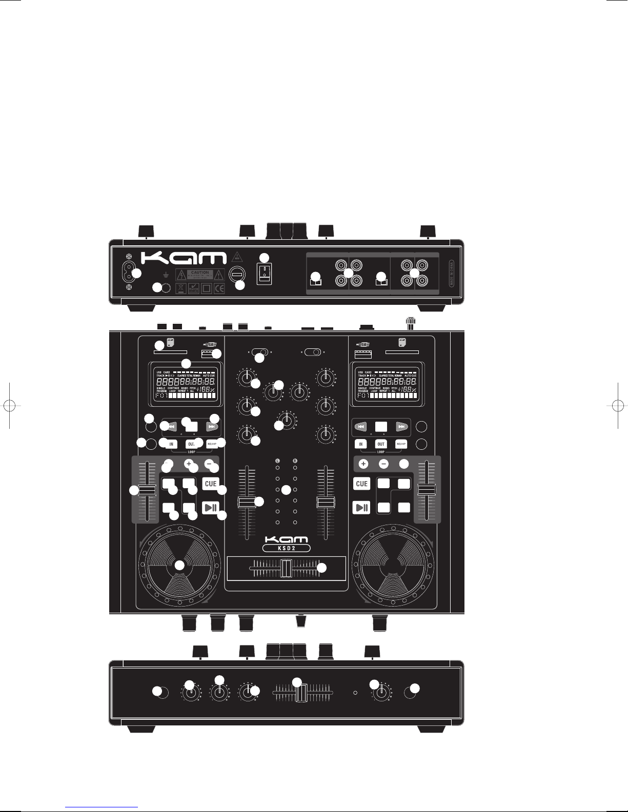
KAM KSD2 UN T FEATURES
1. POWER SW TCH
Press the power switch to turn the unit on. To switch the power off press the switch again.
2. MA NS POWER LEAD
Use this cable to connect the AC mains power to the unit 220/240V.
3. GROUND TERM NAL CONNECTOR
Connect the GND terminal to the turntable ground.
4. FUSE
Under normal operation the fuses should not blow. A blown fuse usually indicates an overload or fault condition. To
change the fuse, remove the fuse by unscrewing the fuse holder cap using a small flathead screwdriver. Refer to
the specification for fuse current ratings. ALWAYS REPLACE THE FUSE W TH THE CORRECT VALUE FOR TH S UN T.
5. NPUT
Plug in a line level or phono level device such as turntable or additional CD player here. Ensure that the correct line
level is selected using the line level switch.
6. L NE/PHONO NPUT LEVEL SW TCH
Use this swich to allow either line level or phono level equipment to be plugged into your channel inputs. f a
turntable is used, the switch must be switched to Phono. When using CD players and other line level units, the
swich must be in the the Line position. Failure to do this may cause damage to your unit.
7. STEREO MA N OUTPUT AND RECORD OUTPUTS
The unbalanced AMP RCA connectors are controlled by the master fader, these should be connected to your
amplifier. The REC RCA connectors are to connect a recording device such as tape player etc.
8. HEADPHONE JACK
Use this to connect headphones for audio monitoring.
9. CUE LEVEL CONTROL
This adjusts CUE (headphone) level output.
10. CUE CROSSFADER
This is used for monitoring between the two input channels. For the headphones output, hard left selects channel
one, hard right selects channel two.
2
Kam KSD2 manual 2.q p:Layout 1 24/7/08 16:11 Page 2

11. M CROPHONE BASS CONTROL
Adjusts microphone bass equalization.
12. M CROPHONE TREBLE CONTROL
Adjusts microphone treble equalization.
13. M CROPHONE LEVEL
Adjusts microphone volume level.
14. M CROPHONE NPUT JACK
Plug in a microphone equiped with a 1/4 inch microphone jack plug or adaptor.
3
10
9
8
7
6
5
4
3
2
1
10
9
8
7
6
5
4
3
2
1
+3
0dB
-3
-8
-10
-13
TREBLE
-12dB +12dB
CH1 GAIN
MIN MAX
MASTER
LEVEL
MIN MAX
MIC LEVEL
MIN MAX
CUE LEVEL
MIN MAX
CH2 GAIN
MIN MAX
MIDDLE
-12dB +12dB
BASS
-12dB +12dB
TREBLE
-12dB +12dB
MIDDLE
-12dB +12dB
BASS
-12dB +12dB
CHANNEL 1
C H A N N E L 1
CHANNEL 1 CHANNEL 2
CHANNEL 2
SD 1
USB 1
PHONO 1
LINE 1
CHANNEL 2
SD 2
USB 2
PHONO 2
LINE 2
C R O S S F A D E R
C U E F A D E R
FOLDER TRACK FOLDER TRACK
SD / USB
SCRATCH SCRATCH
SINGLE / CONT.
ROBO
SD / USB
SINGLE / CONT.
ROBO
TREBLE
-12dB +12dB
BASS
-12dB +12dB
MICROPHONE HEADPHONES
POWER
G R O U N D
AC~220V-240V / 50Hz / 20 Watts
P O W E R
O N
OF F
PHONO 2
LINE 2
PHONO 1
LINE 1
250mAL 250V
REPLACE FUSE AS MARKED
L
R
L
R
L
R
L
R
CH A N N E L 2 CH A N N E L 1
A U D I O I N P U T
RE C AM P
A U D I O O U T P U T
PGM
REPEAT REPEAT
PITCH PITCH
TIME
PGM
TIME
q
w
ert
y y u
i
o
a
s
1@
1#
1$
1%
1^ 1&
1*
1(
2) 2@
2!
2#
2$ 2% 2^
2&
2* 2( 3) 3!
3@
3# 3$ 3%
3^3&
3(4) 4!
3*
4@
4# 4$
4%
Kam KSD2 manual 2.q p:Layout 1 24/7/08 16:11 Page 3

15. D SPLAY
A. SD CARD/USB ND CATOR
B. TRACK NUMBER
This displays the position, number of track of the USB or SD CARD, which is playing.
C. OPERAT NG MODE
These indicate the operating mode of the USB or SD CARD player.
The USB or SD CARD player is playing the USB or SD CARD.
The playback is paused.
D. T ME MODE ND CATORS
ELAPSED: Played time of the selected track.
TOTAL REMA N NG: Total remaining play time of the USB or SD CARD.
REMA N NG: Remaining play time of the selected track.
E. M NUTE, SECOND AND FRAME D SPLAYS
These displays shows the current time, the value changes depends on the time mode selected.
F. T ME BAR ND CATOR
This is a graphical representation of the minute, second and frame displays (C).
G. CUE ND CATOR
This indicates a new cue is set.
H. FOLDER D SPLAY
. PROGRAM ND CATOR
This indicates the player is in program mode
J. PLAY MODE ND CATORS
S NGLE: The USB or SD CARD player is in single mode.
CONT NUE: The USB or SD CARD player is in continue mode.
ROBO: The USB or SD CARD player is in relay mode.
K. LOOP ND CATOR
This indicates the USB or SD CARD player is currently playing in a preset loop.
L . REPEAT ND CATOR
REPEAT 1: The USB or SD CARD player is playing the selected track repeatedly.
REPEAT ALL: The USB or SD CARD player is playing the entire USB or SD CARD repeatedly.
M. P TCH ND CATOR
When "P TCH" is displayed, the pitch slider is functioning
N. P TCH D SPLAY
This indicates the playback speed (pitch), from -16% to +16%.
O. iD3 COMMUN CAT ON D SPLAY
Close up detail of Kam KSD2 display
4
A
H I J K L M N O
B C D E F G
Kam KSD2 manual 2.q p:Layout 1 24/7/08 16:12 Page 4

16. SD PORT
nsert a SD card.
17. USB PORT
nsert a USB memory stick.
18. BASS EQ
This adjusts the bass frequency level of the output signal (left hand set of controls for channel 1 / right hand side
controls for channel 2).
19. M DDLE EQ
This adjusts the mid frequency level of the output signal (left hand set of controls for channel 1 / right hand side
controls for channel 2).
20. TREBLE EQ
This adjusts the high frequency level of the output signal (left hand set of controls for channel 1 / right hand side
controls for channel 2).
21. NPUT TOGGLE SW TCH
Selects which source will be live to that channel based on what you have connected to the rear panel input
section. n left position SD/USB in right position L NE/PHONO are active.
22. GA N CONTROL
The left gain control adjusts the gain level of channel 1,the right gain control adjusts the gain level of channel 2.
23. MASTER LEVEL
Adjusts the main master level output.
24. SD/USB BUTTON
Press once: to read from the SD card
Press again: to read from the USB
Press and hold, display P-OFF and will shut off the power for SD card/USB.
Pressing the button again, will start up the SD/USB.
25. FOLDER/TRACK
Press the folder / track button.
When the button is illuminated the unit is in FOLDER mode, by using the << or >> buttons, you can choose
the folder you wish to access on your memory device.
Press the folder / track button illumination goes out the unit is in TRACK mode press the <<or >> buttons,
to skip through and select tracks.
26. >>
n FOLDER mode >> searches forward through the saved folders on your memory device.
27. <<
n FOLDER mode << searches backwards through the saved folders on your memory device.
n TRACK mode, >> searches forward through the saved tracks on your memory device.
n TRACK mode, << searches backwards through the saved tracks on your memory device.
28. CONT / S NGLE / ROBO BUTTON
n single ROBO mode, pressing the left hand side play/pause button will start the playback of side A if the
cross fader is set in the centre position and both line faders are set at the required level, the unit will play
the track on side A and when finished will automatically start playback on side B this acts as a relay play
(ideal for constant play background music).
n continue ROBO mode, pressing the left hand side play/pause button will start the playback of side A if the cross
5
Kam KSD2 manual 2.q p:Layout 1 24/7/08 16:12 Page 5

fader is set in the centre position and both line faders are set at the required level, the unit will play all the tracks
on side A and when finished will automatically start playback on side B this acts as a relay play (ideal for constant
play background music).
29. N BUTTON (LOOP SYSTEM)
This button sets the beginning of the loop. The Loop indicator on the display flashes.
30. OUT BUTTON (LOOP SYSTEM)
When you press this button, you set the end point of the seamless loop and you start the loop. To finish the loop,
press this button again.
31. RELOOP BUTTON (LOOP SYSTEM)
This button is used to restart the last saved loop.
32. P TCH CONTROL
Use this fader to increase or decrease the speed of the track.
33. P TCH BUTTON
Push this button, to activate the pitch adjustment of slider
34. P TCH BEND + BUTTON
The pitch will automatically increase when the + button is pressed and return to the original pitch When it is
released.
35. P TCH BEND - BUTTON
The pitch will decrease while the - button is pressed and return to the original pitch when it is released.
36. CUE BUTTON
n pause mode use the search button to search the position you want.
Now press play button.
Press CUE button will go back to where you started.
37. PGM BUTTON
n STOP mode, you can program several tracks (20 tracks max)
Press the PAUSE button to enter in the stop mode.
Press the PGM button to enter in the program mode.
Use the skip track buttons to choose the track you want, then press the PGM button to enter your choice.
Press once again the skip track buttons to choose the track you want to listen then press the PGM button
to enter your choice.
Repeat the operation to select the entire tracks you want to listen to.
Press the PLAY / PAUSE button to start the playback of the programmed tracks.
38. REPEAT BUTTON
Use this button to repeat one track or all the tracks of the USB or SD CARD.
39. T ME BUTTON
Use this knob to choose the time mode: Elapsed time, remaining time or total remaining time.
40. SCRATCH BUTTON
When the indicator LED is illuminated, use the jog wheel for SCRATCH function.
41. PLAY / PAUSE BUTTON
Each time you press the PLAY / PAUSE button, the operation changes from play to pause or from pause to play.
Pressing ROBO button activates the S NGLE function, The S NGLE function causes the unit to play one song and
then stop.
6
Kam KSD2 manual 2.q p:Layout 1 24/7/08 16:12 Page 6

On unit 1, pressing ROBO button activates the S NGLE function;
On unit 2, keeping the CONT NUOUS function.
When the S NGLE function causes the unit 1 to play one song and then stop and the CONT NUOUS function causing
the unit 2 to play continuously.
When the unit 1 and unit 2 keep the CONT NUOUS function, when the one unit play the CD to the end and the other
unit play continously.
Pressing the ROBO button a second time activates the ROBO function, starting function causing the unit to
altermate play between two CDs using both sides.
42. JOG & SHUTTLE WHEELS
Shuttle: Use the dial to select the scanning direction and speed. The disc is scanned in the forward direction when
the shuttle dial is turned clockwise from the neutral position, in the reverse direction when the shuttle dial is turned
counterclockwise. The scanning speeds up when the shuttle dial is turned faster.
Jog: n pause mode, if you turn the jog wheel, the point at which the sound is being produced moves by a number
of frames corresponding to the number of clicks. Clockwise moves the point forward; counterclockwise moves the
point backward. n play mode, the jog increases or decreases the speed of the song. (clockwise : increase,
counterclockwise : decrease).
43. NPUT FADER
Controls individual source levels.
44. LED METER
ndicates the master output level.
45. REPLACEABLE CROSSFADER
Controls the output signal between the two input channels. Hard left selects channel 1. Hard right selects channel
2. With the crossfader centered, both assigned channels are live. Use the crossfader for fast and seamless cuts
from one selected channel to the other.
7
Kam KSD2 manual 2.q p:Layout 1 24/7/08 16:12 Page 7

SPEC F CAT ONS
MP3 decoding Support 16/22.05/24/32/44.1/48kHz sampling frequencies
Bit rate 32kbps to 320kbps
Display modes Time / Track Elapsed / Track Remain
Pitch Variable +/-16% slider with resume switch
Pitch bend +/-16% maximum
Bass (channels 1-2) +/-12dB
Middle (Channel 1-2) +/-12dB
Treble (Channel 1-2) +/-12dB
Gain (Channel 1-2) 0 to -20dB
Headphone impedance 32 Ohm
Frequency response 20Hz-20kHz +/-2dB
Distortion Less than 0.02%
S/N ratio Better than 80dB
Channel separation 85dB(1kHz)
Output level 2.0 +/-0.2V R.M.S.
Power supply AC-220~240V 50Hz
Dimensions 325 x 260 x 82mm
Weight 4.0kg
8
© COPYRIGHT LAMBA plc 2008. E&O E.
www.kam.co.uk
Du to continuous product d v lopm nt, sp cifications and app aranc ar subj ct to chang .
If this product is v r no long r functional pl as it tak to a r cycling plant for nvironm ntally fri ndly disposal.
Kam KSD2 manual 2.q p:Layout 1 24/7/08 16:12 Page 8
Table of contents
Other KAM Dj Equipment manuals

KAM
KAM dmx3 User manual

KAM
KAM SuperStar Cluster RGB User manual

KAM
KAM Laserscan Hyper 3D User manual

KAM
KAM KSM Vegas LED User manual

KAM
KAM iLINK RVP User manual

KAM
KAM K-UV 16X3W User manual

KAM
KAM Energy SD300 User manual

KAM
KAM DMX Laser 40 User manual

KAM
KAM Powercan15W User manual

KAM
KAM Mini Par 12 USB User manual

KAM
KAM FloodBank1 User manual

KAM
KAM DMX Star Cluster 3D User manual

KAM
KAM Liteobar 126 User manual

KAM
KAM KMH SERIES User manual

KAM
KAM LED Quadtrix User manual

KAM
KAM LASERSCAN 1000 3D User manual

KAM
KAM Derby FX-Bar User manual

KAM
KAM LED Spiro 1 User manual

KAM
KAM KCD3000 USB User manual

KAM
KAM LED Quadbar 1 DMX User manual