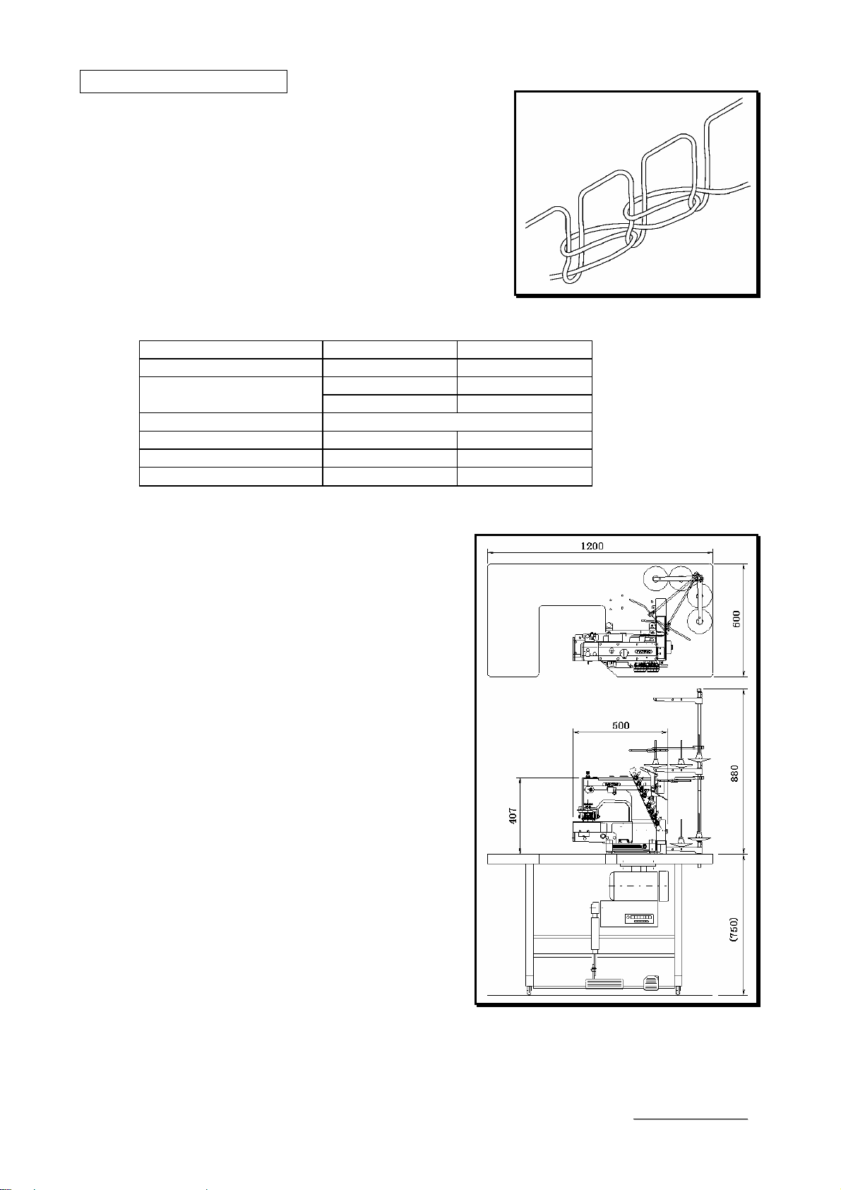
kansai FBX Series User manual

INSTRUCTION
Industrial
Sewing
Machines
FBX1104P
FBX1104
FBX1106P
FBX1106
Second edition
: September 2004
No. 040037

INTRODUCTION
Thank you for your purchasing Kansai Special's FBX Series.
Read and study this instruction manual carefully before beginning any of the
procedures and save it for later use.
1. This instruction manual describes adjustments and maintenance procedures on this
machine.
2. Before starting the machine, check to make sure the pulley cover, safety cover, etc.
are secured.
3. Before adjusting, cleaning, threading the machine or replacing the needle, be sure to
turn off the power.
4. Never start the machine with no oil in the reservoir.
5. Refer to the parts list as well as this instruction manual before performing
preventive maintenance.
6. The contents described in this instruction manual are subject to change without
notice.
Indication of serial number
Zip code
Model
0 4 0 0 0 0 1
Serial number
The date of manufacture
F
F
B
B
X
X
s
s
e
e
r
r
i
i
e
e
s
s

CONTENTS
1. SPECIFICATIONS
1-1 Stitch type ···············································1
1-2 Model ·····················································1
1-3 Diagrammatic sketch of the Series ··············1
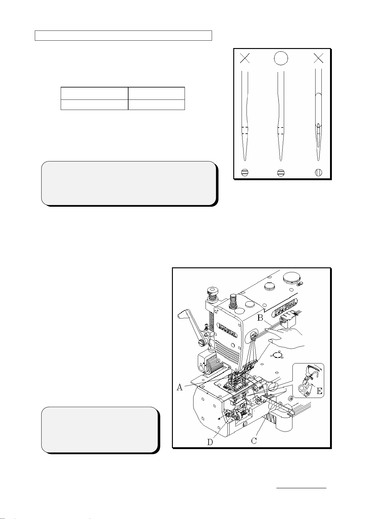
2. NEEDLES & THREADING THE MACHINE
2-1 Needles ···················································2
2-2 Replacing the needle ·································2
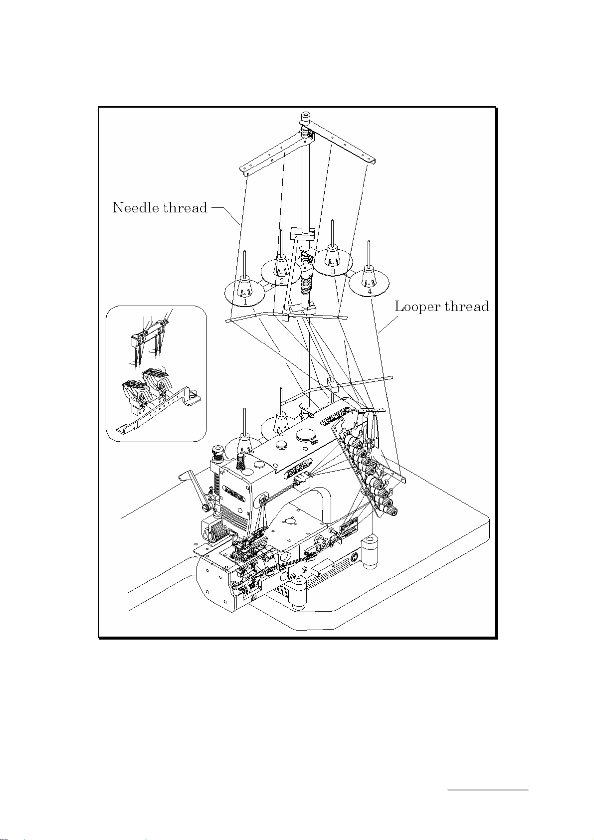
2-3 To thread the machine ······························2
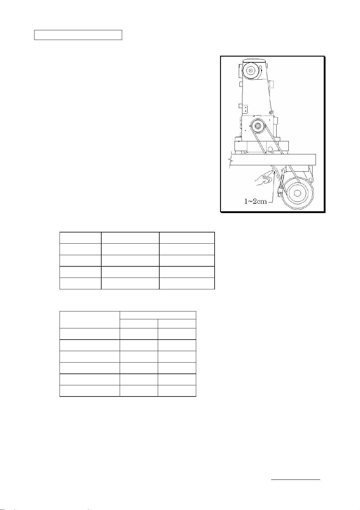
3. MACHINE SPEED
3-1 Machine speed & direction in which the machine
pulley runs ··············································5
3-2 Motor & belt ············································5
4. LUBRICATION
4-1 Oil ·························································6
4-2 To fill the machine with oil ························6
4-3 Replacing the oil and the oil element ···········6
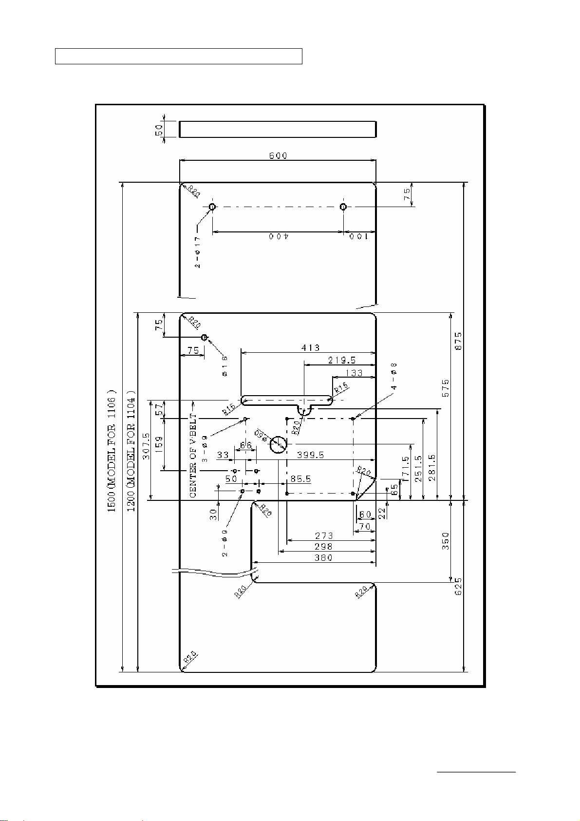
5. SEWING MACHINE INSTALLATION
5-1 Cutting the machine table ·························7
5-2 How to install the machine ························8
6. TO ADJUST THE TIMING BETWEEN
THE UPPER AND THE LOWER SHAFT ·9
7. TIMING OF THE LOOPER TO THE NEEDLES
7-1 Angle for installing the looper and position of the
looper holder bracket································ 10
7-2 Timing of the looper to the needle ············· 11
7-3 Looper setting distance ··························· 12
7-4 Needle height ········································ 12
8. TIMING OF THE RETAINER LOOPER
8-1 Front to back position of the retainer looper ·· 13
8-2 Left to right position of the retainer looper ··· 13
8-3 Adjusting the height of the retainer looper ··· 13
8-4 Timing of the retainer looper to the needle ··· 14
9. ADJUSTING CLEARANCE BETWEEN
NEEDLE AND NEEDLE GUARD ··········· 15
10. ADJUSTING OF THREAD RECEIVER ··15
11. ADJUSTINGTHEFEEDDOG&STITCHLENGTH
11-1 Adjusting of left-right position for the feed dog
····························································16
11-2 Adjusting of front-back position for the feed dog
····························································16
11-3 Adjusting of height for the feed dog ··········16
11-4 Adjusting of stitch length ·······················17
12. ADJUSTING OF THE NEEDLE FEED
12-1 Adjusting of front-back position of the needle
····························································18
12-2 Adjusting of front-back movement amount
of the needle ·········································18
13. ADJUSTING THE PRESSER FOOT
13-1 Presser foot pressure ·····························19
13-2 Position of the presser foot ·····················19
13-3 Foot lift ···············································19
14. ADJUSTING THE REAR PULLER DEVICE
14-1 Manual lever and position of the stopper ··20
14-2 To adjust the puller pressure ··················20
14-3 Adjusting the feeding amount of the rear puller
····························································20
15. ADJUSTING THE STITCH FORMATION
15-1 Thread tension adjustment ·····················21
15-2 Position of the needle thread eyelet ··········21
15-3 Position of the looper thread take-up eyelet ···21
15-4 Silicon Tank ·········································22
16. CLEANING THE MACHINE ···················22
F
F
B
B
X
X
s
s
e
e
r
r
i
i
e
e
s
s

【1】SPECIFICATIONS
1-1 Stitch type
JIS401 double chain stitch machines
1-2 Model Model FBX1104P FBX1106P
No. of needles 2~4 2~12
4 needle threads 6 needle threads
No. of threads 4 looper threads 6 looper threads
Type of tension set Mounted type
Puller width 55mm 78mm
Minimum gauge width 6.4mm 6.4mm
Maximum gauge width 38.1mm 70mm
1-3 Diagrammatic sketch of the Series
1
F
F
B
B
X
X
s
s
e
e
r
r
i
i
e
e
s
s

【2】NEEDLES & THREADING THE MACHINE
2-1 Needles
DV×57 of Schmetz or Organ
Select the proper needle for the fabric and thread.
(Standard #21)
< Needles and needle size >
Schmetz DV×57 Nm90~Nm200
Organ DV×57 #14~#25
2-2 Replacing the needle
When replacing the needle, check the needle carefully
to see that the scarf is turned to the left of the machine
(see the illustration).
< Note >
When replacing the needle, be sure to turn off the
machine. A clutch motor continues running for a while
after the machine is turned off. Therefore keep on
pressing the pedal until the machine stops.
2-3 To thread the machine
Thread the machine correctly by referring to pages 3 to 4.
Incorrect threading may cause skip stitching, thread breakage and/or uneven stitch
formation. When threading the looper, tilt the looper holder toward the front of the
machine using the looper drawing bar.
■To tilt the looper toward the front
1. Bring needle bar A to the top
of its stroke.
2. Pay out the needle thread
from the spool by pressing a
finger down on needle threads
B.
3. Open looper eyelet.
4. Pull drawing lever D out to the
arrow mark as shown in the
illustration so that the looper
holder is tilted toward the
front of machine.
5. After the machine is threaded,
replace the looper by pressing
looper holder E into the
machine until it clicks.
< Note >
The looper pops out of the machine
as soon as lever
D is pulled, so do
not bring your fingers close to the
looper.
2
F
F
B
B
X
X
s
s
e
e
r
r
i
i
e
e
s
s

■FBX1104P
3
F
F
B
B
X
X
s
s
e
e
r
r
i
i
e
e
s
s

■FBX1106P
4
F
F
B
B
X
X
s
s
e
e
r
r
i
i
e
e
s
s

【3】MACHINE SPEED
3-1 Machine speed & direction in which the machine pulley runs
Refer to the table below for maximum and standard
speeds of the Series. To extend machine life, run
the machine approximately 15~20% below the
maximum speed for the first 200 hours of operation
(approx. 1 month).
Then run the machine at the standard speed.
The machine pulley turns counterclockwise as seen
from the end of the machine pulley.
3-2 Motor & belt
Motor : 3-phase, 2-pole, 400W clutch motor
Belt : M type V belt
Select the proper motor pulley according to the
machine speed (refer to the motor pulley outer
diameter on the table below).
Adjust the position of the motor by pressing the
finger onto the middle of the belt so that 1~2cm
deflection can be achieved (see the illustration on
the right).
< Machine speed >
Model Maximum speed Standard speed
FBX1104P 4,000rpm 3,500rpm
FBX1104 4,500rpm 4,000rpm
FBX1106P 3000rpm 2500rpm
FBX1106 3500rpm 3000rpm
< Motor pulley selection table >
Machine speed (SPM)
Motor pulley outer
diameter (mm) 50Hz 60Hz
60 3150 2950
70 2300 3450
80 3300 3900
90 3700 4400
100 4100 (4900)
110 (4500) (5400)
5
F
F
B
B
X
X
s
s
e
e
r
r
i
i
e
e
s
s

【4】LUBRICATION
4-1 Oil
Use Kansai Special’s genuine oil.
(Part No. 28-611)
4-2 To fill the machine with oil
Remove rubber plug A from the oil hole.
Fill the machine with oil until the oil level is at the
top line (see H in the illustration) on oil gauge C.
After the first lubrication, add oil so that the oil
level will be between H and L.
After filling the machine with oil, run the machine
to check the oil is splashing onto oil pot A.
4-3 Replacing the oil and the oil element
To extend machine life, be sure to replace the oil
after the first 250 hours of operation.
To replace the oil, follow the procedures below.
1. Remove the V belt from the motor pulley and
then remove the machine from the table.
2. Remove screw D and then drain the oil.
Be careful not to stain V belt with the oil.
3. After draining the oil, be sure to tighten screw
D.
4. Fill the machine with oil by referring to 4-2
shown above.
If element E is contaminated, proper oiling may not be performed.
Clean the filter element every six months. If just a little or no oil flows out from the
nozzle with the proper amount of oil in the machine, check the element.
To do so, remove oil filter cap F. Replace the element if necessary.
< Note >
When the oil filter cap is rem ved, the oil collected on the element drips. Be careful.
o
6
F
F
B
B
X
X
s
s
e
e
r
r
i
i
e
e
s
s

【5】SEWING MACHINE INSTALLATION
5-1 Cutting the machine table
7
F
F
B
B
X
X
s
s
e
e
r
r
i
i
e
e
s
s

5-2 How to install the machine
1. Install properly as shown in the illustration.
2. Hung a V-belt on the hand pulley.(Refer to[3]machine speed in page no.4)
3. Install the eye guard and the pulley cover.
< Note >
Until all procedures will be done, do not switch on the motor.
8
F
F
B
B
X
X
s
s
e
e
r
r
i
i
e
e
s
s

【6】TO ADJUST THE TIMING BETWEEN THE UPPER AND THE LOWER SHAFT
■Turn the hand pulley and align mark B on the hand
wheel mark P. The needle bar position would be at
the top of its stroke.
■In this case, the line E marked on the lower shaft D
should be vertical. And make sure if the first screw
S of the turning direction is above the V-belt pulley
C or not.
■If not, loosen screw G (4pcs) on the timing pulley F
of the upper shaft to be adjusted to the
above-mentioned position.
Make sure of tightening screw G (4pcs) again after
adjustment.
9
F
F
B
B
X
X
s
s
e
e
r
r
i
i
e
e
s
s

【7】TIMING OF THE LOOPER TO THE NEEDLE
7-1 Angle for installing the looper and position of the looper holder bracket
Insert the looper into the looper holder until the
bottom A of the looper touches to the looper rocker B.
Then tighten screw C.
■As shown in the illustration, the angle between the
looper rocker B and the looper A is 90~92 degrees.
■The clearance between the looper and the needle
when the point of looper passes the scarf of the
needle should be 0~0.1mm. (Adjust by the screw C)
< Note>
Before adjusting machine, be sure to turn off the
motor.
10
F
F
B
B
X
X
s
s
e
e
r
r
i
i
e
e
s
s

7-2 Timing of the looper to the needle
■Turn the hand pulley B pressing push button A
lightly until the push button touches an inside parts
and clicks. And align mark C with the scale no.3 on
the hand pulley B. (Refer to 11-4 stitch length
adjustment on page no.16.)
■Detach your hand from the push button A.
Then turn the hand pulley B and align mark C with
the scale LT on the hand pulley B.
■In this case, turn the hand pulley and check that the
point of looper is 1.6~1.8mm above the needle eye
when the point of looper, moving both to the right
and to the left, reach to the center of the needle.
■In the beginning, the stitch length would be
adjusted to scale no.3. If you need to change it,
procedures are as follows. Remove the rubber plug
F and loosen screw H (2pcs) in the looper eccentric G
to adjust appropriate timing.
Make sure tighten screws H again one by one.
< Note>
Before adjusting machine, be sure to turn off the
motor.
11
F
F
B
B
X
X
s
s
e
e
r
r
i
i
e
e
s
s

7-3 Looper setting distance
■When the needle bar is at the bottom of its stroke,
there should be a distance of approximately 5mm
from the point of the looper to the center of the
needle.
■The adjustment for the looper setting distance is
made by removing plug A and loosening screw C for
the lever B. After adjusting, tighten screw C.
7-4 Needle height
When the needle bar is at the top of its stroke, there
should be a distance of approximately 10mm from
the top surface of the needle plate to point of the
needle. Adjustment is made by loosening screw F
of the needle bar bracket E after removing plug D.
After the adjustment is made, check to make sure
each needle drops correctly into the center of each
needle drop hole.
< Note>
Before adjusting machine, be sure to turn off the
motor.
12
F
F
B
B
X
X
s
s
e
e
r
r
i
i
e
e
s
s

【8】TIMING OF THE RETAINER LOOPER
8-1 Front to back position of the retainer looper
When the needle bar descend from the top to the
bottom of its stroke and the point of the needle A is
same height as the point of the looper retainer B,
there should be a clearance of 2.0~2.2mm between
the point of needle and the point of looper retainer.
(In the beginning, the stitch length is aligned with
scale no.3 on the hand pulley.) when adjusting,
loosen the screw C of the looper retainer bar D and
adjust the front to back position.
*When the stitch length is changed much, necessary
to the adjust again because the clearance would be
changed.
8-2 Left to right position of the retainer looper
When the looper E at the extreme front end of its
travel, the point of the looper retainer should be on
the line F of the looper E.
When adjusting, loosen the screw H of the retainer
looper holder G and adjust the left to right position.
*When the needle bar descend from the top to the
bottom of its stroke and the point of the needle A is
same height as the point of the looper retainer B,
there should be a clearance of 0.8~1.3mm between
the point of the needle A and the left side of the
retainer looper B.
8-3 Adjusting the height of the retainer looper
The retainer looper is the nearest position to the top
of the looper E, there should be a clearance of
0.1~0.4mm between the point of the retainer looper
B and the top of looper E. When adjusting, loosen
the screw H of the retainer looper holde G.
< Note>
Before adjusting machine, be sure to turn off the
motor.
13
F
F
B
B
X
X
s
s
e
e
r
r
i
i
e
e
s
s

8-4 Timing of the retainer looper to the needle
Remove the upper cover A and gasket B.
Remove the screw C and packing D of the bed.
Loosen the screw F (2 pieces) of the retainer looper
eccentric G. Adjust by turning of the retainer
looper eccentric. It is a standard setting to align
the mark J on the retainer looper eccentric G to the
mark K on the lower shaft H.
When aligning the mark J to the mark L which is a
front of the rotating direction, the moving speed of
the retainer looper and the looper thread take-up
lever E against the needle and the looper should be
faster. When aligning the mark J to the mark K
which is a back of the rotating direction, its moving
speed should be slower.
■After adjusting, fasten the screw F of the retainer
looper eccentric G. At the same time, confirm the
clearance of approx. 2.5mm between lower shaft
bush P and the end plate N of the retainer looper
eccentric rod M.
*After this adjusting, confirm to the position of
front/back, the position of left/right and the height of
the retainer looper. (Refer to the previous page)
< Note>
Before adjusting machine, be sure to turn off the motor.
14
F
F
B
B
X
X
s
s
e
e
r
r
i
i
e
e
s
s

【9】ADJUSTING CLEARANCE BETWEEN NEEDLE AND NEEDLE GUARD
Adjustment should be made by pushing of the needle
guard A to the needle B at 0~0.05mm.
Adjusting by turning of the needle guard A after
loosening of the screw D.
【10】ADJUSTING OF THREAD RECEIVER
The clearance of left-right direction between the needle
B and the thread receiver F of the feed dog E is
0.8~1.0mm. At front-back direction, when the needle
B is positioned into the feed dog as fig. by turning of
hand pulley, the top edge of the thread receiver F
should be aligned to the right side line H of the needle.
Adjusting by loosening of the screw G for the thread
receiver F.
15
F
F
B
B
X
X
s
s
e
e
r
r
i
i
e
e
s
s

【11】ADJUSTING THE FEED DOG & STITCH LENGTH
11-1 Adjusting of left-right position for the feed dog
Make sure each needles A drops into the center of
the needle drop hole B of the feed dog J.
Adjusting at left and right by loosening of the screw
D (2 pieces) of the feed rocker C.
At the same time, adjusting by loosening of the
screw H (3 pieces) of the needle plate E, in order to
be equal between each clearance G and also to be
parallel between the feed dog and the feed grooves of
the needle plate E.
11-2 Adjusting of front-back position for the feed dog
When the feed dog is positioned at both the front
dead point and the back dead point by turning of
hand pulley, each clearance F at the front and the
back between the feed dog and the feed grooves of
the Needle plate E is to be equal.
Adjusting at front and back by loosening of the
screw D (2 pieces) of the feed rocker C.
11-3 Adjusting of height for the feed dog
When the feed dog is at the upper dead point, the
feed dog J is to be parallel with the top surface of
the needle plate E. Its height is 1.0~1.2mm.
Adjusting by loosening of nut M and adjusting screw
L of the feed dog J and also the screw K.
After adjusting by up and down of the feed dog J,
fasten the screw K. Then, fix the adjusting screw L
up by the nut M after slight-touching it to the feed
rocker. Tilt adjustment is to be done by loosening
of the screw R of the feed up-down lever P after
removing of the screw N.
16
F
F
B
B
X
X
s
s
e
e
r
r
i
i
e
e
s
s

11-4 Adjusting of stitch length
The stitch length can be adjusted from 2.1 up to 6.4mm without step.
The following table shows the stitch length with the number of stitches within 1”
(25.4mm) and 30mm.
No. of stitches
Pulley position stitch length
(mm)within 1” within 30mm
2 2.1 12 14
3 3.0 8.5 10
4 4.0 6.2 7.5
5 5.0 5.0 6.0
6 6.0 4.2 5.0
L 6.4 4.0 4.5
■How to change the stitch length ( Fig. : Refer to previous page. )
1. Press push button S lightly with the left hand until the end of push button S touches
an inside part.
2. With pressing push button S lightly, turn the hand pulley T by the right hand, until
the push button S goes further into the depth.
3. Press the push button S strongly again. With keeping of this press, turn the hand
pulley T in order to meet the number of pulley position to the mark U which can be
selected as required.
4. After selecting of the desired stitch length, release the left hand.
5. The machine is adjusted the number 3 of pulley position.
In case of happening the defect after big-changing of the stitch length, adjust again
for [7] timing of the looper to the needle, [8] timing of the retainer looper and the
looper.
< Note>
Before adjusting machine, be sure to turn off the motor.
17
F
F
B
B
X
X
s
s
e
e
r
r
i
i
e
e
s
s
This manual suits for next models
4
Table of contents
Other kansai Sewing Machine manuals

kansai
kansai wx-8800 series User manual

kansai
kansai DFB 1400 series User manual

kansai
kansai FX/UTC Series User manual

kansai
kansai MAC100 User manual

kansai
kansai wx-8800 series Owner's manual

kansai
kansai dlr 1500 series User manual

kansai
kansai A-1001 Operating and maintenance manual

kansai
kansai SPX Series Datasheet

kansai
kansai RX UTC User manual

kansai
kansai RX Series User manual