manuals.online logo
Brands
  1. Home
  2. •
  3. Brands
  4. •
  5. kansai
  6. •
  7. Sewing Machine
  8. •
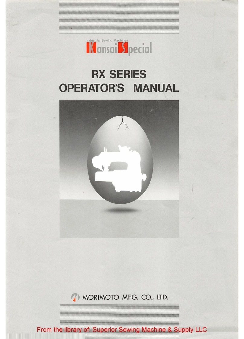
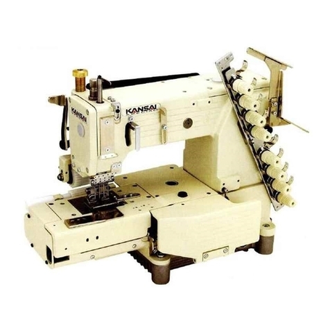
  9. kansai RX UTC User manual

kansai RX UTC User manual

.... •
v?'V":?
.
:>
*
/
Industrial
Sewing
Machines
•
•BH
RX
UTC
MANUAL
,•••...•
•
O
MORIMOTO
MFG.
CO.,
LTD.
From the library of: Superior Sewing Machine & Supply LLC
Table
bf
Contents
1.
Setting
and
Adjusting
The
Needle
Positioner
A.
Attaching
The
Synchronizer
B.
Setting
The
Needle
Position
2.
Stroke
Adjustment
of
The
Knife Air
Cylinder
A.
Piston
Position
8.
Return
Spring
Adjustment
3.
Description
of
The
UTC
Parts
4.
Setting
The
UTC
Knives
and
Springs
A.
Movable
Knife
Position
(Retracted)
B.
Fixed
Knife
Position
C.
UTC
Springs
Adjustments
D.
Movable
Knife
Position
(Extended)
E.
Front/Rear
Position
Adjustments
of
The
Movable
Knife
F.
Movable
Knife/Looper
Clearance
(Front/Back)
5.
Fine
Tuning
The
Adjustments
A.
Movable
KnIfe/Looper
Clearance
(Top/Bottom)
B.
Stationary
Knife
Base
and
Knife
Stopper
Clearance
C
Relationship
of
The
Movable
Knife To
The
Threads
6.
UTC
Spring
Tension
on
The
Looper
Thread
7.
Thread
Tension
Release
Adjustments
A.
Tension
Release
Block/Cylinder
Bracket
Clearance
B.
Tension
Opener
and
Pull Off
Hook
Positions
C.
Tension
Release
Assembly
8.
Knife
Position
Sensor
9.
Pressure
Regulator
Page
1
4-6
7-8
9-10
11
11
From the library of: Superior Sewing Machine & Supply LLC
l!^etting
and
Adjusting
The
Needle
Positioner
(Refer
to
Fig
1&
2)
[CAUTION]
When
setting
up
the
synchronizer
make
sure
all
connections
for
the
UTC
unit
are
unplugged
to
prevent
knife
activation
during
the
setting
procedure.
Follow
motor
manufacturer
s
instructions
for
setting
needle
position.
Fig 1:
To
attach
the
synchronizer
to
the
machine,
secure
screws
(B)
on
pulley
synchronizer
hub
(F).
To
adjust
the
depth
of
the
synchronizer
bar
(C)
loosen
nut
(D)
and
turn
synchronizer
bar
(C).
Fig
2:
To
set
''needle
up'''
position,
align
mark
P
on
machine
handwheel
(E)
with
rivet
(0)
on
machine
casting.
This
is
the
proper
timing
position.
^With
two
position
motor
use
needle
down
then
needle
up.
From the library of: Superior Sewing Machine & Supply LLC
2^troke
Adjustment
of
The
Knife
Air
Cylinder
(Refer
to
Fig
3&
4)
Fig
3:
Depress
the
knife
cylinder
piston.
Measure
the
clearance
between
cushion
(D)
and
collar
(A).
Clearance
should
be
15-15.5mm
as
shown
in
(C).
Fig
4:
Adjustment
of
the
air
cylinder
return
spring:
Clearance
from
the
collar
(B)
and
the
cylinder
bracket
is
shown
as
dimension
(C).
It
should
be
7mm
when
the
piston
is
fully
extended.
To
adjust
loosen
the
screw
in
collar
(B),
set
the
correct
clearance
and
tighten
the
screw.
-ict-
15-15.5cm
From the library of: Superior Sewing Machine & Supply LLC
^^^escription
of
The
UTC
Parts
Adjustment
Nut
Cam
Adjustment
•Alignment
Mark
Looper
Thread
Catcher
Blade
Knife
Drive
Arm
Needle
Thread
Catcher
Blade
Stationary
Knife
-Guide
Screw
Movable
Knife
Base—' ^
Stationary
Knife
Base
Movable
Knife
Movable
Knife
Guide-
•Stationary
Knife
Stopper
Movable Knife Height Adjustment
From the library of: Superior Sewing Machine & Supply LLC
^j^etling
The
UTC
Knives
and
Springs
(Refer
to
Rg
6H6)
Fig 6; Position of the movable knife : As shown in Fig 6 it is critical
that
movable knife (A) be
aligned evenly with movable knife base (B).
The
edge of the base should be parallel with
the
knife. To
adjust
loosen screw (C)
and
realign properly.
Fig
7:
Position
of
the
fixed
knife.
Description
of
Parts:
A -
Movable
Knife.
a -
Needle
Thread
Catcher
Blade.
a'
-
Looper
Thread
Catcher
Blade.
D -
Stationary
Knife.
d -
Stationary
Knife
Cutting
Edge.
E -
Screws
for
Adjusting
Stationary
Knife.
When
fully
retracted
the
looper
thread
catcher
blade
(a')
should
be
0.5-0.8mm
behind
the
stationary
knife
cutting
edge
(d).
To
adjust,
loosen
screws
(E)
and
set
the
proper
clearance
as
described
above.
From the library of: Superior Sewing Machine & Supply LLC
Fig
8: Adjust the lowtension spring (F) so that the needlethreads are cut and released cleanly
while the looper thread is cut and held in place by the low tension spring (F).
Spring
adjustments
are
made
by loosening
the
following
screws:
Screws
(E)
allow
for
adjustment
of
the
movable
knife
and
the
low
tension
spring.
Screws
(I) allow
for
adjustment
of
the
high
tension
spring.
The
distance
from
the
edge
of
the
stationary
knife
to
the
leading
edge
of
the
high
tension
spring
should
be
1.2
to
1.5mm.
The
leading
edge
of
the
low
tension
spring
should
extend
0.5mm
beyond
the
edge
of
the
stationary
knife.
Note:
Make
sure
that
the
needle
threads
are
cleanly
released
and
not
held
by
this
spring.
Fig
9:
With
knife
fully
extended
the
tip
of
the
movable
knife
should
be
even
with
the
front
edge
of
the
looper
(Line
A).
The
tip
of
the
movable
knife
is
2.5mm
past
the
center
of
the
looper
eye.
Fig 8
1.2~1.5mm
0.5
mm
Fig 9
[*,
II
p
(FRONT)
2.5mm
From the library of: Superior Sewing Machine & Supply LLC
Fig 10:
To
adjust
the
front/rear
position
of
the
movable
knife,
loosen
screw
(C)
and
adjust
cam
(D)
in
direction
(A)
to
move
the
knife
to
the
rear
or
direction
(B)
to
move
the
knife
forward.
Fig 11:
With
the
knife
fully
retracted,
the
clearance
between
the
rear
edge
of
the
looper
and
the
front
edge
of
either
the
movable
or
stationary
knife
is
4.5~5.0mm.
Fig 10
(o\
C—V
\\ A
^ \ B
D-^
Fig 11
in
From the library of: Superior Sewing Machine & Supply LLC
5>
ine
Tuning
The
Adjustments
(Refer
to Rg 3 &5)
To
increase
the
clearance
between
the
looper
and
the
knife
refer
to
Fig 5
and
loosen
the
adjustment
nuts.
If it is
required
to
bring
the
knife
forward,
adjust
the
nuts
so
as
to
reduce
dimension
(Z). If it is
required
to
bring
the
knife
back,
then
adjust
the
nuts
so
as
to
increase
dimension
(Z).
An
alternative
method
for
increasing
or
decreasing
the
clearance
between
the
looper
and
the
knife
is
to
adjust
the
stroke
of
the
knife
cylinder
piston
as
shown
in Fig 3.
To
increase
the
clearance
between
the
knife
and
the
looper,
increase
the
clearance
between
cushion
(D)
and
collar
(A).
When
any
adjustments
are
made
to
the
stroke
of
the
knife
air
cylinder,
it
is
required
that
the
position
of
the
knife
be
readjusted.
The
recommended
clearance
between
the
top
of
the
looper
and
the
movable
knife
is
0.5
~1.0mm
as
shown
in
Fig
12.
To
adjust
the
height
between
the
looper
and
the
movable
knife,
refer
to
Fig
13.
Loosen
screws
(A)
and
raise
or
lower
the
bracket
(E)
so
as
to
obtain
the
proper
clearance
as
shown
in
Fig
12.
From the library of: Superior Sewing Machine & Supply LLC
Fig 13:
Clearance
between
stationary
knife
base
and
stationary
knife
stopper:
As
the
knife
is
extended
it
first
moves
forward
over
the
looper.
At
this
time
the
stationary
knife
base
contacts
the
stationary
knife
stopper.
At
this
time
the
movable
knife
guide
(C)
gently
touches
the
movable
knife
base
so
as
to
stabilize
the
motion
of
the
knife.
Fig
14
&
15;
Correct
position
of
movable
knife
:
Fig
14
demonstrates
the
incorrect
stroke
of
the
movable
knife
resulting
in
the
knife
not
catching
the
needle
thread
(B)
and
looper
thread
(D).
Fig
15
demonstrates
the
cor
rect
stroke
of
the
movable
knife.
As
this
diagram
shows,
the
knife
passes
through
the
center
of
the
needle
threads
and
in
front
of
the
looper
thread
thereby
enabling
the
blade
to
catch
and
cut
the
threads
properly.
Fig 13
From the library of: Superior Sewing Machine & Supply LLC
ITC
Spring
Tension
on
The
Looper
Thread
(Refer
to
Fig
16)
Fig
16:
To
increase
tension
on
the
looper
thread,
turn
screw
(A)
clockwise.
To
decrease
tension
on
the
looper
thread
turn
screw
(A)
counter-clockwise.
bread
Tension
Release
Adjustments
(Refer
to
Fig
17
Fig
17:
Clearance
between
the
tension
release
block
(B)
and
the
cylinder
bracket
is 3.0
mm.
To
obtain
this
clearance
loosen
screw
(C)
and
adjust.
Fig 18:
There
should
be
a
slight
clearance
bet
ween
the
tension
openers
(B)
and
the
tensions.
For
maximum
pulloff,
the
thread
pulloff
hooks (A)
should
lightly
touch
the
threads
when
the
machine
is
sewing.
Front
of
Machine
From the library of: Superior Sewing Machine & Supply LLC
Fig 19:
Tension
Release
Assembly
A -
Screw
B -
Collar
0 -
Tension
Post
Holder
D -
Thread
Pulloff
Post
E -
Post
Guide
F -
Thread
Pulloff
Lever
G -
Screw
(controls
adjustment
for
all
of
D)
H -
Collar
1 -
Screw
(sets
position
of
J)
J -
Thread
pulloff
hook
0
w
Fig 19
10
From the library of: Superior Sewing Machine & Supply LLC
nife
Position
Sensor
(Refer to Fig 20)
Fig
20:
Adjustment
of knife
speed
in
regards
to
extension
and
retraction:
If
the
knife
is
in
any
position
other
than
the
rest
position,
except
during
knife
activation,
the
sensor
will
prevent
the
motor
from
operating
thereby
preventing
damage
to
the
knife
and
gauge
parts.
(E)
shows
a
clearance
of
1.8mm
between
the
sensor
and
the
tension
release
arm.
Flow
control
valve
(F)
controls
knife
extension
speed.
Flow
control
valve
(G)
controls
knife
retraction
speed.
Note:
Make
sure
that
both
flow
control
valves
are
not
set
too
fast
so
as
to
prevent
damage
to
the
knife
unit.
ressure
Regulator
(Refer
to
Fig
21)
Fig 21:
Set
the
pressure
between
4^5
kilograms
per
centimeter
squared.
Note:
Operate
at
the
lowest
pressure
possible
for
consistent
knife
operation.
From the library of: Superior Sewing Machine & Supply LLC
(T-''
MORIMOTO
MFG.
CO.,
LTD.
MAIN
FACTORY
180,
Suna
Shijohnawate-city,
Osaka
575,
Japan
Tel: (0720) 77-1221 Telex: 5349134 KSPCAL-J
Fax:(0720)78-9649
TOKYO
OFFICE
5-16-7,
KohtobashI
Sumida-ku,
Tokyo
130,
Japan
Tel:
(03) 3635-5121
Fax:
(03)
3635-5123
OKAYAMA
OFFICE
Village
Okuda
IF, 24-19,
Okuba-Honmachi
Okayama-clty
700,
Japan
Tel:
(0862)
32-9120
Fax:
(0862)
22-8292
KANSAI
SPECIAL
U.S.A.
CORP.
640
Gotham
Parkway
Caristadt
N.J.
07072
U.S.A.
Tel:
(201)
460-0350
Telex: 219449 (KSPCUR)
Fax:
(201) 460-1633
MORIMOTO MFG. (H.K.)
LTD.
203-207
G/R, Lai Chi Kok Road,
Sham
Shui Po, Kowloon, Hong Kong
Tel:
3-918357-9
Telex:
31167
MORHK
NX
Fax:3-7891707
MORIMOTO MFG. (H.K.)
LTD.
SINGAPORE REP. OFFICE
1 Marine
Parade
Central
=10-01
Parkway Builders, Centre Singapore 1544
Tel;
3457576
Telex:
RS25138
A/B:
MMSPL
Fax:
3449603
KANSAI
SPECIAL
EUROPE
G.M.B.H.
Wahler
Strasse
37
4000
Dusseldort,
30
GERMANY
Tel:
0211-658020
Telex;
8586555
KSWGD
Fax:
0211-6581529
KANSAI
SPECIAL
EUROPE
G.M.B.H.
TURKEY
LIAISON
OFFICE
IMC2,
Block No.2606, Unkapani, Istanbul,
TURKEY
PUB
NO
OM-RX/UTC92(0
Tel:
(1)527-6230
Fax : (1)527-6317
PRINTED
IN
JAPAN
From the library of: Superior Sewing Machine & Supply LLC

Other kansai Sewing Machine manuals

kansai wx-8800 series Owner's manual

kansai

kansai wx-8800 series Owner's manual

kansai RX Series User manual

kansai

kansai RX Series User manual

kansai SPX Series Datasheet

kansai

kansai SPX Series Datasheet

kansai R9000 User manual

kansai

kansai R9000 User manual

kansai MAC100 User manual

kansai

kansai MAC100 User manual

kansai FX SERIES User manual

kansai

kansai FX SERIES User manual

kansai FBX Series User manual

kansai

kansai FBX Series User manual

kansai FX/UTC Series User manual

kansai

kansai FX/UTC Series User manual

kansai DFB 1400 series User manual

kansai

kansai DFB 1400 series User manual

kansai wx-8800 series User manual

kansai

kansai wx-8800 series User manual
kansai DVK-1700 series User manual

kansai

kansai DVK-1700 series User manual

kansai DWR-1900 Series User manual

kansai

kansai DWR-1900 Series User manual

kansai A-1001 Operating and maintenance manual

kansai

kansai A-1001 Operating and maintenance manual

kansai dlr 1500 series User manual

kansai

kansai dlr 1500 series User manual
Popular Sewing Machine manuals by other brands

Janome 1200D brochure

Janome

Janome 1200D brochure

Siruba DL7200B manual

Siruba

Siruba DL7200B manual

Brother EF4-B511 instruction manual

Brother

Brother EF4-B511 instruction manual

Grace Little Rebel instruction manual

Grace

Grace Little Rebel instruction manual

Singer 2517 Instruction book

Singer

Singer 2517 Instruction book

Singer 118W4 Instructions for using

Singer

Singer 118W4 Instructions for using

Singer 211W151 parts list

Singer

Singer 211W151 parts list

White Quilter's Star 1780 Instruction book

White

White Quilter's Star 1780 Instruction book

JUKI MO-1000 instruction manual

JUKI

JUKI MO-1000 instruction manual

UnionSpecial 80800 INSTRUCTIONS AND ILLUSTRATED PARTS MANUAL

UnionSpecial

UnionSpecial 80800 INSTRUCTIONS AND ILLUSTRATED PARTS MANUAL

Pfaff 3114 Instruction book

Pfaff

Pfaff 3114 Instruction book

KANSAI SPECIAL WX Series instruction manual

KANSAI SPECIAL

KANSAI SPECIAL WX Series instruction manual

ELNA EnVision 8006 Supplementary instructions

ELNA

ELNA EnVision 8006 Supplementary instructions

Brother DB2-B737 MKII parts manual

Brother

Brother DB2-B737 MKII parts manual

ZOJE ZJ781-BD Service manual

ZOJE

ZOJE ZJ781-BD Service manual

Sew Easy 7520 quick guide

Sew Easy

Sew Easy 7520 quick guide

JUKI MH-481 specification

JUKI

JUKI MH-481 specification

Singer 410W1 Instructions for using and adjusting

Singer

Singer 410W1 Instructions for using and adjusting

manuals.online logo
manuals.online logoBrands
  • About & Mission
  • Contact us
  • Privacy Policy
  • Terms and Conditions

Copyright 2025 Manuals.Online. All Rights Reserved.