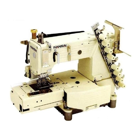
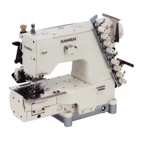
kansai R9000 User manual

Kansai
Special
INSTRUCTION
MANUAL
R.
9 O O O
Anntfjj
From the library of: Superior Sewing Machine & Supply LLC

TABLE
OF
CONTENTS
TOPIC
PAGE
1.
R-9000
1
2.
MACHINE
TYPES 1
3.
MACHINE
SPEED 1
4.
NEEDLES 2
5.
TABLESTAND ASSEMBLY 2
6.
MACHINE
OIL
AND
FILTER
REPLACEMENT 3
7.
THREADING
AND
TENSION
ADJUSTMENT 4
S.
ADJUSTMENT OF THE LOOPER
POSITION
5
9.
ADJUSTMENT OF THE NEEDLE BAR
HEIGHT
6
10.
FEED
LENGTH ADJUSTMENT 6
11.
ADJUSTMENT
OF
THE
DIFFERENTIAL
FEED
7
12.
ADJUSTMENT
OF
THE
FEED
DOG
HEIGHT
7
14.
ADJUSTMENT
OF
THE
NEEDLE
GUARD 8
15.
ADJUSTMENT
OP
THE
TAKE UP 8
16.
ADJUSTMENT
OF
THE
TAKE
UP CAM 8
17.
POSITION
OF
THE
NEEDLE
LEVER
EYELET
8
18.
ADJUSTMENT
OF
THE
TOP
COVER MECHANISMS 9
19.
THE UNDERBED THREAD CUTTER
(UTC)
10
From the library of: Superior Sewing Machine & Supply LLC

I.R9000
TYPE
WIDTHflN^
WIDTH
fGA)
NmEBARHT.
liXHR-NEL.
niSIM3
TWO
NEEDLE
MACHINE
1/8
8
gauge
4
5/3
21 0 gauge 4
3/16
1 2 gauge 4
7/3
2
14
gauge
4
1/4
1 6 gauge 4
THREE
NEEDLE
MACHINE
7/3
2
14
gauge 4
1/4
1 6
gauge
4
a'
^
2.
MACHINE
TYPES
IN
THE
R-9000
SERIES
R-9101
R-9102
R-9103
R-9202 R-9203
1
needle
2
needle
3
needle
2
needle
3
needle
1looper 1looper 1looper 1
looper
1looper
double
chainstitch
bottan
coverstitch
bottom
coverstitch
top
and
bottom
coverstitch
top
and
bottom
coverstitch
Um28GAS
needle
size
75
to
100
UYX128GAS
needle
giy**
75
to
100
UYX128GAS
needle
gry**
75
to
100
Um28GAS
needle
size
75
to
100
Um28GAS
needle
size
75
to
100
differential
feed
differential
feed
differential
feed
differential
feed
ri-iffgffPnHfll
feed
3.
MACHINE SPEED
AND
MOTOR
PULLEY
The
correct
combinations of motor pulley
sizes
and machine
speeds are seen on the chart
below*
Choose
the appropriate
pulley
size
according to the desired
machine
running speed.
PULLEY
DIAMETER
MAOllMESEm
(REM)
50
HZ
60
HZ
4000
85
70
4500
95
80
5000
110
90
NOTE:
The normal
rotation
of
the
handwheel
is
counter
clockwise,
or
in
the
direction
of
the
operator.
From the library of: Superior Sewing Machine & Supply LLC

.
^xLlul,l:3
4-1
NEEDLE
TYPE
The
needle
specified
for
use
in
the
R-9000
series
machines
is
UYX1286AS.
The recommended
size
range
is
from
size
75
to
100. The
size
used
should
be
selected
according
to
the
sewing
conditions.
SINGBl
SlSIBl
9
10
1 1
12
13
14
hmiCSlCSlBl
65
70
75
80
85
90
4-2
INSTALLAHON
OF
THE
NEEDLES
Install
the
needles
so
that
their
Clearance
Above
the
Eye
(CAE)
is
exactly
in
the
back.
Be
sure
to
insert
the
needle
all
the
way
into
the
needle
clamp
so
that
it
touches
its
base.
Then
tighten
set
screw
A.
5.
ASSEMBLY OF
THE
TABLESTAND
-2-
Fig.
1
From the library of: Superior Sewing Machine & Supply LLC

6.
MACHINE
OIL
AND
FILTER
REPLACEMENT
6.1
OIL
SUPPLY
The
lubricating
oil
recommended
for
our
sewing
machines
is
TELESSO
33.
To
supply
1.
Remove
the
oil
pot
on
top
of
the
machine
top
cover.
Insert
a
funnel
into
the
opening
and
pour
the
oil
into
the
funnel.
2.
Pour
in
the
oil
only
until
the
oil
level
reaches
between
the
two
marks
on
the
oil
gauge.
3.
Replace
the
oil
pot.
Fig.
3
Note: While
the
machine
is
in
operation,
watch
to
see
the
oil
is
splashing on
the
inside
of the
oil
pot.
6.2
DRAINING
THE
OIL
To
drain
the
machine
oil,
remove
the
oil
drain plug from the
front
of
the
reservoir.
6-3.
REPLACING
THE
FILTER
1.
Remove
the
cover
plate,
"A"
on
the
bottom
of
the
oil
reservoir.
Filter
"B"
can
now
be
seen.
2.
Remove
the
filter
by
gently
pulling
it
from
the
feed
port
stem,
"C".
3.
Replace
a new
filter
onto
the
feed
port
stem.
NOTE:
1. Always check
the
oil
gauge
before
using
the
machine
to
ensure
the
oil
level
is
correct.
2. Use
only
the
oil
specified
or
its
equivalent.
3.
there
is
no
oil
splashing
in
the
oil
pot,
even though
the
oil
level
is
correct,
this
suggests
there
is
a
clog
in
the
oil
filter
or
oil
line.
Clean
or
replace
the
oil
filter.
The
.inside
of
the
oil
reservoir
should
also
be
cleaned
.periodically.
-3-
drain
From the library of: Superior Sewing Machine & Supply LLC

7.
THREADING
AND
TENSION
ADJUSTMENT
7-1
THREADING
Place
the
thread through
the
eyelets
and guides according
to
the diagram
below<
Lines
"D"
represent needle threads,
line
"E"
is
the
top cover
thread,
and
line
"F"
is
the
looper
thread.
5
7-2.
TENSION ADJUSTMENT OF THE
THREAD
The
appropriate thread tension varies according to the
sewing
conditions
(the
kind of
fabric,
the type of thread,
the
stitch
length
used,
etc.).
Adjust
the
thread
tension
with
the
tension
regulator
nut
to
suit
the
sewing
conditions.
A
Turning
the
regulator
nut
clockwise
increases the
tension.
Turning
the
regulator
nut
counter
clockwise
decreases
the
tension*
NOTE:
The
thread
tension
should
be
maintained
as
low
as
possible
to
form a good
stitch.
Setting
the
thread
tension
unnecessarily
high
is
likely
to
cause
thread
breakage
or
skipping.
-4-
A
and
B
are
needle
threads
C
is
the
looper
thread
From the library of: Superior Sewing Machine & Supply LLC

8.
ADJUSTMENT OF THE LOOPER
POSITION
8-1
THE
LOOPER-NEEDLE
DISTANCE
At
the
time
the
looper
is
in
its
extreme
right
position,
the
needles
must
be
in
their
lowest
psotion.
At
this
time,
the
looper-needle
distance,
"D",
from
the
tip
of
the
looper
to
the
right
side
of
the
most
right
needle
must
be
Amm.
This
adjustment
may
be
made by
loosening
the
looper
drive
lever
clamp
screw,
"E" and
repositioning
the
looper
holder.
8-2
THE
LOOPER-NEEDLE
CLEARANCE
128mm
o
Fig.
7
The
looper
must
pass
behind
the
needles
to
catch
the
needle
loop
to
form
the
stitch.
The
looper
position
must
be
adjusted
so
that
at
this
time
the
clearance
between
the
tip
ofthe
looper,
"A"
below,
and
the
needle,
"C",
is
0
to
0.05mm.
C
Fig'
8
Fi8'
9
This adjustment
may
be
made
by loosening the clamp screw, "H",
on
the
looper
rocker
lever,
"B", and
repositioning
the
looper
behind
the
needles.
-5-
From the library of: Superior Sewing Machine & Supply LLC

AL>J
uo
X
ur
xnii
nriJCttfLJCi
oak
nuixoni
The
correct
needle bar
heights
for
the
various needle gauges
are
listed
below. To
adjust,
remove
the
machine head
cover.
Next, loosen the
clamp
screw,"?",
shown
in
figure
11*
Move
needle
bar,"G",
to
the
appropriate
height
and
retighten
the
clamp
screw.
NEEDLE
GAUGE WIDTH
NEmE
BAR
HEEGHT
1/8'
—3.
1 7
5/32---3.96
3/32----4.76
7/32----5.56
1/4---6.35
Fig.
10
10.
FEED
LENGTH
ADJUSTMENT
NOTE:
The
needle
bar
height
is
the
dimension
from
the
top
face
of
the
needle
plate
to
the
tip
of
the
left-^ost
needle,
(see
Figure
10)
y
The
feed
length
adjustment
of
the
R-9000
series
machines
is
by a
pushbutton
system.
To
adjust,
lower
the
front
cover
on
the
bed
of
the
machine.
You
will
see
pushbutton,"A",
shown
in
the
illustration.
Push
the
button
and
turn
12
«0
(j (]
A\n
•
J
the
handwheel
until
the
pin
falls
into
place.
Then
turn
the
handwheel
while
holding
down
the
button.
Turning
the
handwheel
in
the
"I"
direction
makes
the
stitch
larger.
Turning
the
hand-
wheel
in
the
"H"
direction
-6-
makes
the
stitch
shorter.
From the library of: Superior Sewing Machine & Supply LLC

1 1 ADJUSTMENT OF THE
DIFFERENTIAL
FEED
Expose
the
access
port
by removing
the
rubber plug
as
shown
in
Figure 13. At
this
time you can
see
nut "B". To
adjust
the
differential
feed,
loosen
nut
"B"
and
move
the
lever
up
FiR. 13
or
down
the
differential
guide
plate.
Moving
the
lever
up
increases
the
differential.
Moving
the
lever
down
decreases
the
differential.
Retighten
nut
"B",
12.
ADJUSTMENT
OF
THE
FEED
DOG
HEIGHT
As shown
in
Figure
14,
the
height
of
the
feed
dog
should
be
one
full
tooth
height
or
0.8
to
1.2mm.
The
height
of
the
main
feeder
is
adjusted
by
loosening
set
screw
"A".
The
height
of
the
differential
feeder
is
adjusted
by
set
screw
"B".
-7-
n
r-?
rn
(
Fig.
14
0.8~1.2o/ai
From the library of: Superior Sewing Machine & Supply LLC

adjustment
of
the
needle
guard
As
the
looper
is
moving from
right
to
left
behind
the
needlesi
the
tip
of
the
looper
will
reach
the
center
line
of
the
first
(right-most)
needle.
At
this
time,
the
needle
guard'
must
be
in
contact
with
the
needles.
The
dimension
from
the
point
of
the
contacting
surface
to
the
tip
of
the
needles
should
be
0.8
to
1mm
and
the
right-most
needle
should
be pushed
slightly
forward
0.1
to
0.3mm by
the
needle
guard»
as
shown
in
Figure
16.
Adjustments
of
the
needle
guard
height
and
angle
with
respect
to
the
needle
line
are
made
with
set
screw
A.
Front-back
position
adjustment
is
made
with
set
screw
"C".
Retighten
all
set
screws
after
adjusting.
0.8
to
Iflm
0.1
to
0.3im
Fig.
16
15.
ADJUSTMENT OF THE TAKE UP
6-7o/d
As shown
in
Figure
17,
the
dimension
between
the
bottom
of
the
retainer
"B",
and
the
take
up
plate,
"E",
should
be
6
to
7mm.
Adjust
this
dimension
with
set
screw
"F".
Also,
as
shown,
the
eye
of
the
looper
thread
guide,
"A",
should
be
in
line
with
the
center
of
the
main
shaft.
Adjust
the
position
of
the
thread
guide
with
the
set
screw
"G".
1 6
ADJUSTMENT
OF
THE
TAKE
UP
CAM
main
shaft
As shown
in
Figure
18,
the
looper
thread
should
be
released
from
the
take
up cam when
the
tip
of
the
left-most
needle
I
reaches
the
bottom
surface
of
the
looper
at
V
the
time
the
needles
are
on
their
downward
stroke.
Fig.
18
17.
POSITION
OF
THE
NEEDLE
LEVER
EYELET
At
the
time
the
needle
lever
eyelet
is
in
its
upper-most
position,
the
tip
of
the
eyelet
should
be
in
line
with
the
"0"
mark on
the
graduated
plate
in
front.
Fig.
19
Fig.
17
Fig.
20
as
shown
in
Figure
19.
To
adjust,
loosen
the
set
screw,"C",
Figure
20,
and
move
the
lever
arm
up
or
down
as
necessary.
shown
in
Retighten.
- 8 -
From the library of: Superior Sewing Machine & Supply LLC

18.
ADJUSTMENT OF THE TOP
COVER
MECHANISMS
a)
TOP
COVER
THREAD
GUIDE
The
eye
of
the
top
cover
thread
guide
should
be
in
line
with
the
"3"
mark
of
the
graduated
plate
in
front.
To
adjust,
loosen
set
screw "D" and
move
the
top
cover
thread
guide,"C",
up
or
down
as
necessary
(see
Figure
21).
Retighten
the
set
screw.
b)
TOP
COVER
LOOPER
The
distance
between
the
top
surface
of
the
needle
plate
and
the
bottom
surface
of
the
top
cover
looper
is
8mm,
as
shown
in
Figure
22.This
is
adjusted
by
loosening
set
screw
"K"
in
Figure
23, and
moving
to
top
O.Sm/m
cover
looper
to
the
appropriate
position
Retighten
the
set
screw.
The dimension
between
the
top
of
the
top
cover
looper
and
the
bottom
of
the
zig-zag
eyelet
should
be
set
at
O.Smm
(Figure
22).To
adjust,
loosen
the
set
screws
"A"
and
move
the
eyelet
up
or
down.
The
dimension
from
the
top
of
the
zig
zag
eyelet
and
the
bottom
of
the
L-guide
eyelet
should be
Imm.
Use
set
screw "B" to
adjust.
Fig.
21
)
n,)i
m n m i
,r7
c) TOP
COVER
LOOPER
WITH
RESPECT
TO
THE
NEEDLES
As
the
hook
tip
passes
the
right-most
needle,
there
should
be
a
clearance
of
0.5mm,
as
shown
in
Figure
23.
At
the
time
the
top
cove
looper
reaches
its
left-most
position,
the
dimension
from
the
hook
tip
to
the
left-most
needle
should
be
5
to
5.5mm
A
5~5.5En/n
r.
O.So/n
Fig.
23
These
two
dimensions
as
described
are
accomplished
by a
combination
of adjustments of the
top
cover
looper within the spreader lever,"J"
(loosen
sete
screw"K"
to
adjust),
and the
position
of
the
spreader
lever,"J"
itself
(loosen
set
screw "L" to
adjust).
-9-
From the library of: Superior Sewing Machine & Supply LLC

19~1
THE
MOVABLE
K.i<xi
4-
r..xiEEiio
TO
THE
LOOPER
AND NEEDLE
THREADS.
Movable
knife
Point
A;
Looper
thread
blade
Point
B:
Needle
thread
blade
Looper
thread
Looper
Needle
threads
FIG.
24
THE EXTREME
LEFT
POSITION
OF THE
MOVABLE
KNIFE
IS
SHOWN
IN
FIGURE
1 ABOVE.
THE
CORRECT
POSITION
IS
AS FOLLOWS: THE
MOVABLE
KNIFE
MUST
PASS
THROUGH
THE
NEEDLE
THREAD
LOOP(S)
AND
STOP IN
SUCH
A
POSITION
THAT THE LOOPER THREAD
IS
BEHIND
THE LOOPER THREAD BLADE
AND
THE NEEDLE
THREAD(S)
ARE
BEHIND
.THE
NEEDLE
THREAD
BLADE.
PLEASE
OBSERVE THE
FIVE
POSSIBLE
CASES
ILLUSTRATED
AT
THE
RIGHT:
In
Case
(a),
neither
the
needle
thread
nor
the
looper
threads
are
cut.
In
Case
(b),
both
the
needle
thread
and
the
looper
thread
are
cut.
However,
since
the
looper
thread
is
not
being
cut
by
the
looper
thread
blade,
it
will
not
be
caught
under
the
plate
spring
for
holding
and
will
not
be
picked
up
with
the
next
stitch.
In
Case
(c),
neither
the
needle
thread
nor
the
looper
threads
are
cut.
In
Case
(d),
both
the
needle
thread
and
the
looper
thread
will
be
cut.
However,
because
the
movable
knife
did
not
pass
though
the
needle
loop,
the
needle
thread
will
be
cut
in
the
wrong
position
and
an
irregular
feeding
of
the
remain
ing
needle
thread
will
result.
In
Case
(e),
the
knife
is
in
the
correct
position
and
all
of
the
threads
will
be
cut
properly
and
the
looper
thread
will
be
caught
and
kept
under
the
plate
spring.
-1
0-
(a)
(b)
(c)
(d)
(e)
FiK»
25
From the library of: Superior Sewing Machine & Supply LLC

(a)
POSmON
OF
THE
MOVABLE
KNIFE
AT
FULL
EXTENSION
In
order
for
the
knife
to
Jut
the
threads
in
the
correct
manner,
the
blade
must
be
Positioned
as
shown
in
Figure
2/
When
the
movable
knife
is
ft
full
extension
(the left-most
position), the
dimension
"V*
in Figure26must be 1 to
l.Smm.
That
is,
the
tip
of the needle thread blade must be 1 to
l.Smm
to
the
left
of
the
left-most
needle.
To
adjust,
loosen
set
screw "36" in Figure28 and
move
the
Needle
stopper
35'
to the
left
or right, as appropriate.
Then
retighten
set
screw
"36".
Needle
thread
blade
Lxxjper
thread blade
k
Fig.
27
Mavahle
knife
—A
(b)
POSmON
OF THE
MOVABLE
KNIFE
WITH
RESPECT
TO
THE
LOOPER
"Die
tip
of
the
movable
knife
should be
positioned
as
shown
in
Figure27above.
At the time
the
tip
comes
to
the
center
of
the
needle
bar,
the
tip
should
be
positioned
toward
the
rear
two
thirds.thickness
of
the
looper
(see
illustration).
To
adjust
this
position,
loosen
the
set
screws
of
the
assembly 00-6010-9 as in FigureZ^and
correct
the
position.
Retighten
the
set
>p
24
23
Fig.
28
- n _
Fig.
26
Fig.
29
From the library of: Superior Sewing Machine & Supply LLC

0 0
0 O O 0
Point
P
FIG.
30
As
seen
in
Figure
30
above,
the
standard
position
of
the
blade
of
the
fixed
knife
is
15mm
(dimension
"a")
to
the
right
of
the
needle
center
line.
If
it
is
necessary
to
adjust
this
position,
dimension
"a" can
be
altered
by
loosening
set
screws
"5"
and
moving
the
stopper
plate
"4" to
the
left
or
right.
No
clearance
is
allowed
between
the
fixed
knife
base
"3"
and
the
movable
knife
base
"6"
at
"Point
P",
as
it
will
cancel
the
cushioning
effect
of
spring
"7".
To
adjust
"Point
P"
after
the
fixed
knife
position
has
been
established,
loosen
nuts
"44"
and
"46"
in
Figure 28and turn the connecting rod "45"
either
clockwise
or
counter
clockwise
as
is
appropriate.,
when
there
is
no
longer
any
space
at
"Point
P",
tighten
the
nuts
"44" and
"46".
To
set
the
stroke
of
the
movable
knife,
loosen
set
screws
"30"
in
Figure
28 and move
stopper
"29"
in
either
direction
suitable.
(D)
SET
POSITIONS
OF
THE
MOVABLE
KNIFE,
FIXED
KNIFE,
AND
PLATE
SPRING
Movable
knife
to
the
stationary
knife:
As
shown
in
Figure
31
the
end
face
of
the
needle
blade
of
the
movable
knife
is
aligned
with
the
side
edge
of
the
stationary
knife.
To
adjust,
loosen
set
screws "8"
in
Figure30 and
reposition
the
movable
knife.
Retighten
the
screws.
Plate
spring to the
movable
knife:
As
shown
in
Figure
31
The edge of the
plate
spring should
line
up with
the
edge of
the
movable
knife
between
the
looper
thread
blade
and
the
needle
thread
blade
(both
edges
aligned
with
line
"X"),
Plate
spring to the
stationary
knife:
As
shown
in
Figure
31
the
tip
of
the
low
tension
plate
spring
should
extend
about
1mm
beyond
the edge of the
stationary
knife (see dimension"C").
Low
tension to high tension plate springs:
As
seen in Figure 32
the
tip
of
the
low
tension
spring
should
extend
about
2.5mm
beyond
the
tip
of the high tension spring (see
dimension
"D").
These
adjustments
may
be
made
by
loosening
the plate spring set
screws, repositioning the plate springs,
and
retightening.
-
17
-
From the library of: Superior Sewing Machine & Supply LLC

movable
knife
stationary
knife
edge
plate
spring edge
Fig«
31
Fig.
32-
looner
thread
blade
needle
thread
blade
needle
thread
release
\ looper thread catching
plate
spring
tension
adjustnent
scret/
JcM-tensim spring
high
taision
spring
19-2 WIPER
ADJUSTMENT
(R-9i01/UTC;
R-9102A,C/UTC;
R-9103A,C/UTC)
After
the
knife
unit
has
cut
the
thread,
the
wiper
("1"
in
Figure
34) moves from
its
uppermost
position
to
the
left
to
pass
between
the
needle
thread
holder
plate
spring,"3",
and
the
retaining
wire,"2",catch
the
two
needle
threads,'
and
return
to
its
uppermost
position
(shown
in
Figure
To
adjust:
I)
The wiper
position
with
respect
to
the
needles:
Fig.
34
* align the
end
face of the
needle
thread
Uade
vdth
the
stationary
kidfe.
plate
spring
set
screws
knife
Fig.
33
Set
the
wiper so
that
the
inner
hook edge
Is
0
to
Imm
away
from
the
line
of
the
needle
face
(see
Figure
33
above).
Loosen
set
screw
"A"
and
slide
the wiper
shaft
in
or out to the appropriate
position.
From the library of: Superior Sewing Machine & Supply LLC

2) To
adjust
the
wiper
height:
Move
lever
"19"
in
Figure
35 from
its
upper-most
position
to
its
lower-most
position.
At
this
time,
the
bottom
face
of
the
wiper
should
be
7mm
above
the
face
of
the
needle
plate
(see
Figure
36).
To
adjust,
loosen
the
set
screw
"1"
in
Figure
36 and
turn
the
wiper
shaft
up
or
down
appropriately
to
the
proper
position.
Retighten
the
set
screw..
3)
The
position
of
the
wiper
in
its
lower-most
position
with
respect
to
the
needles:
At
the
time
the
wiper
comes
to
its
lower-most
position,
the
tip
of
the
hook
should
be
2
to
3mm
to
the
left
of
the
left-most
needle
(see
Figure
33).
To
adjust,
loosen
the
set
screw
"2"
on
stopper
cam
"3"
in
Figure
36.
Turn
the
cam
until
the
desired
position
is
attained.
Retighten.
4)
The
position
of
the
wiper
in
its
upper-most
position:
At
the
time
the
wiper
is
resting
in
its
upper-most
position,
the
tip
of
the
wiper
should
be
21
to
22mm
above
the
face
of
the
needle
plate
(see
Figure
35)..
To
adjust,
loosen
the
set
screws
"32" and
"33"
fixing
levers
"19"
and
"28"
respectively,
as
shown
in
Figure
36a.
Reposition
the
levers
and
retighten
the
set
screws.
5)
The
position
of
the
thread
holder
plate
spring
and
retainer
wire:
These
parts
should
be
set
16
to
17mm
to
the
right
of
the
needle
bar
center
(see
Figure
35).
To
adjust,
loosen
set
screws
"4"
and
"5"
in
Figure
35
and
shift
the
bracket
"6"
to
the
left
or
right
as
necessary.
Retighten.
The
tip
of
the
thread
holder
plate
spring
should
be
10mm
above
the
face
of
the
needle
plate.
To
adjust,
loosen
the
set
screws
"4"
and
"5"
in
Figure
34
and
move
the
needle
holder
plate
spring,"3",
and
retainer
wire,
"2"
up
or
down
to
the
correct
position.
Retighten
the
set
screws.
-
14
-
/ S «
!• i gv
16
—
17mm
Fig.
35
Fig.
36
12
13.
Fig.
36a
From the library of: Superior Sewing Machine & Supply LLC

19-3
ADJUSTMENT
OF
THE
THREAD
PULL
MECHANISM
The
thread
pull
mechanism
is
activated
along
with
the
knife
mechanism.
The
standard
setting
is
shown
in
the
illustration
to
the
right.
To
vary
the
length
of
the
tails
of
the
cut
thread,
the
position
of
the
thread
hooks
(#"3")
must
be
altered.
Lowering
the
hooks
closer
to
the
thread
increases
the
length
of
the
tails.
Raising
the
hooks
away
from
the
thread
shortens
the
length
of
the
tails.
To
adjust
the
position,
loosen
set
screws
"4",
change
to
the
desired
position
and
retighten
the
set
screws.
19-4
INSTALLATION
OF
THE
MACHINE
HEAD
The
machine
head
is
to
be
installed
onto
the
tablestand
in
accordance
with
the
diagram
below.
Fig.
38
0 0
0
Fig.
37
From the library of: Superior Sewing Machine & Supply LLC

'•!
' i
• r
-
r.-:
y
•'
'•'; y
• ;••
Aii
.
,
.sIT
•
rv,
vno
ili
ojr
From the library of: Superior Sewing Machine & Supply LLC
Table of contents
Other kansai Sewing Machine manuals

kansai
kansai FX/UTC Series User manual

kansai
kansai dlr 1500 series User manual

kansai
kansai wx-8800 series User manual

kansai
kansai RX UTC User manual

kansai
kansai DVK-1700 series User manual

kansai
kansai DWR-1900 Series User manual
kansai
kansai RX Series User manual

kansai
kansai FBX Series User manual

kansai
kansai SPX Series Datasheet

kansai
kansai FX SERIES User manual