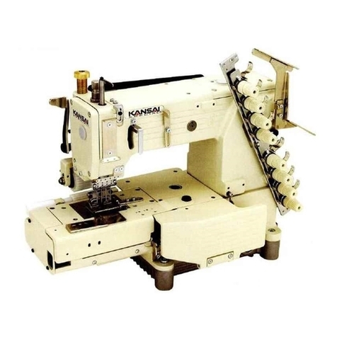
kansai SPX Series Datasheet

INSTRUCTION & PARTS
INSTRUCTION & PARTSINSTRUCTION & PARTS
INSTRUCTION & PARTS LIST
LISTLIST
LIST
Industrial
IndustrialIndustrial
Industrial
Sewing
SewingSewing
Sewing
Machines
MachinesMachines
Machines
2003 年8月初版発行
First published : August2003
No. 030153
SPX-101

S
SS
S
S
SS
SP
PP
P
P
PP
PX
XX
X
X
XX
Xs
ss
s
s
ss
se
ee
e
e
ee
er
rr
r
r
rr
ri
ii
i
i
ii
ie
ee
e
e
ee
es
ss
s
s
ss
s
は
はは
は
じ
じじ
じ
め
めめ
め
に
にに
に
INTRODUCTION
INTRODUCTIONINTRODUCTION
INTRODUCTION
この度は、カンサイスペシャル
SPX
シリ−ズをお買上げ頂きまして誠に有難うござい
ます。
本書をよくお読み頂き調節方法を十分御理解の上、末長く御愛用下さいますようお願
い致します。
Thank you for your purchasing Kansai Special's SPX Series.
Read and study this instruction manual carefully before beginning any of the
procedures and save it for later use.
1. 本書は、ミシンの調整,取扱いに関して作成したものです。
This instruction manual describes adjustments and maintenance procedures on this
machine.
2. ミシンの調整,掃除,糸通し,針交換などをする時は必ず電源を切ってから行って下さ
い。
Before adjusting, cleaning, threading the machine or replacing the needle, be sure to
turn off the power.
3. 保全作業を行う時はこのマニュアルだけでなくパーツリストと合わせてご利用下さい。
Refer to the parts list as well as this instruction manual before performing
preventive maintenance.
4. この使用説明書に記載された内容は、改良のため予告なく変更する事があります。
The contents described in this instruction manual are subject to change without
notice.

S
SS
S
S
SS
SP
PP
P
P
PP
PX
XX
X
X
XX
Xs
ss
s
s
ss
se
ee
e
e
ee
er
rr
r
r
rr
ri
ii
i
i
ii
ie
ee
e
e
ee
es
ss
s
s
ss
s
目
目目
目
次
次次
次
CONTENTS
CONTENTSCONTENTS
CONTENTS
1. 使用針と糸の通し方 / NEEDLES & THREADING THE MACHINE
1-1 使用針と使用糸の目安 / Standard needle and threads ・・・・・・・・・・・・・・・・・・・・・・・・・・・・・・・・1
1-2 針の取付け方 / Replacing the needle ・・・・・・・・・・・・・・・・・・・・・・・・・・・・・・・・・・・・・・・・・・・・・・・1
1-3 針板の取外し方 / How to remove needle post ・・・・・・・・・・・・・・・・・・・・・・・・・・・・・・・・・・・・・・・1
1-4 糸の通し方 / To thread the machine ・・・・・・・・・・・・・・・・・・・・・・・・・・・・・・・・・・・・・・・・・・・・・・・2
2. 縫速度 / MACHINE SPEED
2-1 縫速度とプーリーの回転方向 ・・・・・・・・・・・・・・・・・・・・・・・・・・・・・・・・・・・・・・・・・・・・・・・・・・・・・・3
Machine speed & direction in which the machine pulley runs
2-2 モーターとベルト / Motor & belt ・・・・・・・・・・・・・・・・・・・・・・・・・・・・・・・・・・・・・・・・・・・・・・・・・・3
3. ミシンへの給油 / LUBRICATION ・・・・・・・・・・・・・・・・・・・・・・・・・・・・・・・・・・・・・・・・・・・・・・・・4
4. テーブルの加工 / CUTTING THE MACHINE TABLE ・・・・・・・・・・・・・・・・・・・・・・・・・・・5
5. ルーパーと針のタイミングの調整 / TIMING OF THE LOOPER TO THE NEEDLE
5-1 ルーパーの取付け / To install the looper ・・・・・・・・・・・・・・・・・・・・・・・・・・・・・・・・・・・・・・・・・・・・6
5-2 ルーパー引き量 / Looper setting distance ・・・・・・・・・・・・・・・・・・・・・・・・・・・・・・・・・・・・・・・・・・・6
5-3 ルーパーの往き帰りのタイミング / Looper left-to-right movement ・・・・・・・・・・・・・・・・・・・・・7
6. 上送り歯の調整 / ADJUSTING UPPER FEED DOG
6-1 送り歯の高さ / Height ・・・・・・・・・・・・・・・・・・・・・・・・・・・・・・・・・・・・・・・・・・・・・・・・・・・・・・・・・・・・8
6-2 送り歯の前後位置 / Front to back position ・・・・・・・・・・・・・・・・・・・・・・・・・・・・・・・・・・・・・・・・・・8
6-3 送り歯の上下運動 / Up to down movement ・・・・・・・・・・・・・・・・・・・・・・・・・・・・・・・・・・・・・・・・・・8
6-4 送り量の調整 / Feeding volume ・・・・・・・・・・・・・・・・・・・・・・・・・・・・・・・・・・・・・・・・・・・・・・・・・・・9
6-5 送り歯押え圧の調整 / Adjusting pressure of feed dog ・・・・・・・・・・・・・・・・・・・・・・・・・・・・・・・・9
7. 糸調子に関する調整 / STITCH FORMATION
7-1 下糸捌きの位置 / Position of bottom thread take-up ・・・・・・・・・・・・・・・・・・・・・・・・・・・・・・・・10
7-2 下糸捌きと針のタイミング / Timing of needle and bottom thread take-up ・・・・・・・・・・・・・11
7-3 上糸捌きの位置 / Position of upper thread take-up ・・・・・・・・・・・・・・・・・・・・・・・・・・・・・・・・・11
< PARTS LIST >
< PARTS LIST >< PARTS LIST >
< PARTS LIST >
1. フレ−ム関係 / FRAME ASSEMBLY ・・・・・・・・・・・・・・・・・・・・・・・・・・・・・・・・・・・・・・・・・・・・12
2. 針棒上軸機構 / NEEDLE BAR MECHANISM ・・・・・・・・・・・・・・・・・・・・・・・・・・・・・・・・・・14
3. 上送り機構 / TOP FEED MECHANISM ・・・・・・・・・・・・・・・・・・・・・・・・・・・・・・・・・・・・・・・・16
4. ル−パ−機構 / LOOPER MECHANISM ・・・・・・・・・・・・・・・・・・・・・・・・・・・・・・・・・・・・・・・・18
5. 糸道機構 / THREAD EYELET MECHANISM ・・・・・・・・・・・・・・・・・・・・・・・・・・・・・・・・・・20
6. 糸立、アクセサリ− / THREAD STAND AND ACCESSORIES ・・・・・・・・・・・・・・・・22
1
S
SS
S
S
SS
SP
PP
P
P
PP
PX
XX
X
X
XX
Xs
ss
s
s
ss
se
ee
e
e
ee
er
rr
r
r
rr
ri
ii
i
i
ii
ie
ee
e
e
ee
es
ss
s
s
ss
s
【1】使用針と糸の通し方 / NEEDLES & THREADING THE MACHINE
1
11
1-
--
-1
11
1 使用針と使用糸の目安
使用針と使用糸の目安使用針と使用糸の目安
使用針と使用糸の目安 /
//
/ Standard n
Standard nStandard n
Standard needle
eedleeedle
eedle and threads
and threadsand threads
and threads
針/ Needle 上糸 / Needle thread 下糸 / Looper thread
オルガン / Organ
DV-K39-NY #14 スパン / Spun
#30 スパン / Spun
#50
オルガン / Organ
DV-K39-NY #16 スパン / Spun
#20 スパン / Spun
#30
1
11
1-
--
-2
22
2
針の取付け方
針の取付け方針の取付け方
針の取付け方 /
//
/ Replacing the needle
Replacing the needleReplacing the needle
Replacing the needle
針を取り替える時は、針の向きを確かめエグリを右方向に
して図のように正しく取付けて下さい。
When replacing the needle, check the needle carefully
to see that the scarf is turned to the right of the
machine (see the illustration).
1
11
1-
--
-3
33
3 針板の取外し方
針板の取外し方針板の取外し方
針板の取外し方 / How to remove n
/ How to remove n/ How to remove n
/ How to remove needle post
eedle posteedle post
eedle post
針棒を上死点にして、上送り揚げレバーを揚げます。
レバーX,Y を同時にさげ、針板ポスト(前)Aを手前にス
ライドさせると針板ポスト(前)Aがとれます。
また、保全などで針板ポスト(裏)B を外したい時は、ネジ
Cを外してレバーX,Y を同時にさげ、針板ポスト(裏)B
を後方にスライドさせると針板ポスト(裏)
Bがとれます。
After making the needle bar at the top of its stroke, lift
up the upper feed. Push down both levers X, Y at the
same time, then pull the front needle post A to the
arrow direction and remove it. In case of taking the
back post B off to repair, loosen 2 screws C and do
same procedure when removing the front post A.
< 注/ Note >
針を取り替える時は、必ず電源を切って下さい。
クラッチモ−タ−をご使用の時は電源を切ってもモ−タ−
は惰性で回る為、ミシンが停止するまでペダルを踏み続けて
下さい。
When replacing the needle, be sure to turn off the
machine. A clutch motor continues running for a while
after the machine is turned off. Therefore keep on
pressing the pedal until the machine stops.

2
S
SS
S
S
SS
SP
PP
P
P
PP
PX
XX
X
X
XX
Xs
ss
s
s
ss
se
ee
e
e
ee
er
rr
r
r
rr
ri
ii
i
i
ii
ie
ee
e
e
ee
es
ss
s
s
ss
s
1
11
1-
--
-4
44
4
糸の通し方
糸の通し方糸の通し方
糸の通し方 /
//
/ To thre
To threTo thre
To thread the machine
ad the machinead the machine
ad the machine
図を参考にして間違いのないよう通して下さい。
間違った糸の通し方をした場合、目飛び,糸切れ,調子ムラ等の原因になります。
Thread the machine correctly by referring to the illustration below.
Incorrect threading may cause skip stitching, thread breakage and/or uneven stitch
formation.

3
S
SS
S
S
SS
SP
PP
P
P
PP
PX
XX
X
X
XX
Xs
ss
s
s
ss
se
ee
e
e
ee
er
rr
r
r
rr
ri
ii
i
i
ii
ie
ee
e
e
ee
es
ss
s
s
ss
s
【2】縫速度 /
MACHINE SPEED
2
22
2-
--
-1
11
1 縫速度とプーリーの回転方向
縫速度とプーリーの回転方向縫速度とプーリーの回転方向
縫速度とプーリーの回転方向
Machine speed & direction in which the machine pulley runs
Machine speed & direction in which the machine pulley runsMachine speed & direction in which the machine pulley runs
Machine speed & direction in which the machine pulley runs
このミシンの最高縫速度は 900rpm で、常用縫速度は
800rpm です。新しいミシンを使用する時は、最初の
200 時間(約 1ケ月)は最高縫速度の約 15~20% 低い
回転数で運転した後に、常用縫速度で使用すると耐久
性から見ても良い結果が得られます。プーリーの回転
方向は図のようにプーリー側から見て右回りです。
Maximum speed : 900 rpm
Standard speed : 800 rpm
To extend machine life, run the machine
approximately 15~20% below the maximum speed
for the first 200 hours of operation (approx. 1
month).
Then run the machine at the standard speed.
The machine pulley turns clockwise as seen from
the end of the machine pulley (see the illustration).
2
22
2-
--
-2
22
2 モーターとベルト
モーターとベルトモーターとベルト
モーターとベルト /
//
/ Motor & belt
Motor & beltMotor & belt
Motor & belt
モーターは 3相4極のクラッチモータ−を、ベルトは M型Vベルトを使用して下さい。
モータープーリーは表からミシンの回転数に合った外径のプーリーを選んで使用して下さい。
Vベルトは、図のようにベルトの中間を指で押して 1~2 ㎝たわむようにモ−タ−の位置を調
節して下さい。
Motor : 3-phase, 4-pole clutch motor
Belt : M type V belt
Select the proper motor pulley according to the machine speed (refer to the motor pulley
outer diameter on the table below). Adjust the position of the motor by pressing the
finger onto the middle of the belt so that 1~2cm deflection can be achieved (see the
illustration).
<モ−タ−プ−リ−選定表 / Motor pulley selection table>
ミシンの回転数 (SPM)
Machine speed
モータープーリ
ーの外径 (mm)
Motor pulley
outer diameter 50Hz 60Hz
40 750 900
50 850

4
S
SS
S
S
SS
SP
PP
P
P
PP
PX
XX
X
X
XX
Xs
ss
s
s
ss
se
ee
e
e
ee
er
rr
r
r
rr
ri
ii
i
i
ii
ie
ee
e
e
ee
es
ss
s
s
ss
s
【3】ミシンへの給油 / LUBRICATION
■ミシンを使用する時は、矢印の油孔、ブッシュに注油を行って下さい。
Before using the machine, lubricate a few drops of oil in the arrow points.

5
S
SS
S
S
SS
SP
PP
P
P
PP
PX
XX
X
X
XX
Xs
ss
s
s
ss
se
ee
e
e
ee
er
rr
r
r
rr
ri
ii
i
i
ii
ie
ee
e
e
ee
es
ss
s
s
ss
s
【4】テ−ブルの加工 / CUTTING THE MACHINE TABLE

6
S
SS
S
S
SS
SP
PP
P
P
PP
PX
XX
X
X
XX
Xs
ss
s
s
ss
se
ee
e
e
ee
er
rr
r
r
rr
ri
ii
i
i
ii
ie
ee
e
e
ee
es
ss
s
s
ss
s
【5】ルーパーと針のタイミングの調整 / TIMING OF THE LOOPER TO THE NEEDLE
5
55
5-
--
-1
11
1 ルーパーの取付け
ルーパーの取付けルーパーの取付け
ルーパーの取付け / To
/ To/ To
/ To install the looper
install the looperinstall the looper
install the looper
ルーパーは、ルーパー台の奥まで入れてアタリの位置に気
を付けてネジを締めて下さい。
The looper install to the end of looper holder and
tighten screw at the flat point marked up on the looper
bar.
5
55
5-
--
-2
22
2 ルーパーの引き量
ルーパーの引き量ルーパーの引き量
ルーパーの引き量 / Looper setting distance
/ Looper setting distance/ Looper setting distance
/ Looper setting distance
ルーパーの引き量は、ルーパーが最も引いた時ルーパー先
端から針までが 3mmになるのが基本です。
調節は、ルーパーギアー(小)のネジ Aを緩めて行って
下さい。ネジ Aを締めた後、ルーパーシャフトに上下の
ガタが無いことを確認して下さい。
Set the looper so that the distance from points of the
looper to the side of needle is 3 mm when the looper is
at the farthest position from the needle.
Adjust by screws A and not to be even a little play at
the looper shaft.

7
S
SS
S
S
SS
SP
PP
P
P
PP
PX
XX
X
X
XX
Xs
ss
s
s
ss
se
ee
e
e
ee
er
rr
r
r
rr
ri
ii
i
i
ii
ie
ee
e
e
ee
es
ss
s
s
ss
s
5
55
5-
--
-3
33
3 ルーパーの往き帰りのタイミング
ルーパーの往き帰りのタイミングルーパーの往き帰りのタイミング
ルーパーの往き帰りのタイミング / Looper left
/ Looper left/ Looper left
/ Looper left-
--
-to
toto
to-
--
-right movement
right movementright movement
right movement
図のようにルーパーの先端が針の中央に来た時に往き
帰り共、同じ位置になります。(同時タイミング)
針とルーパーのタイミングを調整するには、ネジ Bを
緩めておこないます。スクイ高さは、針糸穴より約 2.5
mm(エグリの中心)に合わせます。
針の高さの調節はネジ Cを緩めて行います
When the looper moves from left to the right on the
needle, the point of looper should pass 2.5mm above
the top of its needle’s eye ( at the center of needle ).
Adjust by the screws B for the timing between the
needle and the looper and by the screws C for the
needle height.

8
S
SS
S
S
SS
SP
PP
P
P
PP
PX
XX
X
X
XX
Xs
ss
s
s
ss
se
ee
e
e
ee
er
rr
r
r
rr
ri
ii
i
i
ii
ie
ee
e
e
ee
es
ss
s
s
ss
s
【6】上送り歯の調整 / ADJUSTING UPPER FEED DOG
6
66
6-
--
-1
11
1 送り歯の高さ
送り歯の高さ送り歯の高さ
送り歯の高さ / H
/ H/ H
/ Height
eighteight
eight
送り歯の高さ調節は、ネジ Dを緩めて行って下さい。
下げすぎるとパッカリングが起きやすく、上げすぎる
と生地を送りません。製品の厚み分を目安にして下さ
い。
(出荷時は、約 1.8mm になっています。)
To make the adjustment of height, loosen screw D.
Too much down may cause puckering, too much up
may cause no-feeding of the fabric.
The height of upper feed dog should be adjusted
with the thickness of products (goods)
approximately.
Factory standards of the height of upper feed dog is
adjusted with 1.8mm.
6
66
6-
--
-2
22
2 送り歯の前後位置
送り歯の前後位置送り歯の前後位置
送り歯の前後位置 / F
/ F/ F
/ Front
rontront
ront to back position
to back positionto back position
to back position
ネジ Fを緩め、軸 Eを回転させることで、送り歯の前
後位置を変更できます。送り歯と針が当たらない様に
注意して下さい。
Turn the shaft E after loosening of screw F, so that
the front to back position of feed dog is changeable.
Be careful not to touch feed dog and needle.
6
66
6-
--
-3
33
3 送り歯の上下運動
送り歯の上下運動送り歯の上下運動
送り歯の上下運動 / Up to down movement
/ Up to down movement/ Up to down movement
/ Up to down movement
ネジ Gの調整で、送り歯の上下運動の高さを変更することができます。
ナット Hとネジ Gの端までが約 2mmになるのが基準で、この時、カム Mを一回転させると
カムフロアーLは、常にカム Mと接します。調整を行った後は、上送り棒抱き Iと上送り土
台Kブッシュ Jとの間に隙間がある事を確認して下さい。
Adjust the screw G, so that the height for up to down movement of feed dog is changeable.
2 mm distance between nut H and screw G is a standard setting.
At this condition, cam floor L always comes in contact with cam M when one turning of
cam M. After adjusting, confirm there are some tolerance in properly between feed dog
connecting link I and feed dog plate K / bush J.
< 注/ Note >
TYPE-1 の送り歯(GP-178)使用時、軸 Eのマ−クは右側
になっています。(工場出荷時)
In case of the type 1 of the feed dog (GP-178), the
marking of shaft E would be right side.
(Standard position)
< 注/ Note >
TYPE-1 の送り歯(GP-178)を使用する時、送り量の最大は 3mm となります。
In case of the type-1 (GP-178) of the feed dog, the feeding amount would be 3mm in the
maximum.

9
S
SS
S
S
SS
SP
PP
P
P
PP
PX
XX
X
X
XX
Xs
ss
s
s
ss
se
ee
e
e
ee
er
rr
r
r
rr
ri
ii
i
i
ii
ie
ee
e
e
ee
es
ss
s
s
ss
s
6
66
6-
--
-4
44
4 送り量の調整
送り量の調整送り量の調整
送り量の調整 / Feeding volume
/ Feeding volume/ Feeding volume
/ Feeding volume
ボルト Oを緩め、調節ネジ Nを時計方向に回せば送り
量が小さくなり、反対に回せば送り量が大きくなりま
す。
送り歯と針があたらない事を確認してボルト Oを締め
て下さい。
Loosen wing nuts O, turn adjusting screw N to
clockwise direction to make a small of feeding
volume. Turn it opposite direction to make a big.
After confirming not to touch feed dog and needle,
fasten butterfly nut O.
6
66
6-
--
-5
55
5 送り歯押え圧の調整
送り歯押え圧の調整送り歯押え圧の調整
送り歯押え圧の調整 / Adjusting pressure of feed dog
/ Adjusting pressure of feed dog/ Adjusting pressure of feed dog
/ Adjusting pressure of feed dog
押え圧力は安定した縫目と送りが働く範囲で、できる
限り弱い圧力で調整して下さい。
図のように時計方向に回すと圧力が強くなります。
The pressure of feed dog should be adjusted as light
as possible, within the range of obtaining the stable
stitch formation and feeding.
To increase the pressure, turn it to clockwise
direction as per fig.

10
S
SS
S
S
SS
SP
PP
P
P
PP
PX
XX
X
X
XX
Xs
ss
s
s
ss
se
ee
e
e
ee
er
rr
r
r
rr
ri
ii
i
i
ii
ie
ee
e
e
ee
es
ss
s
s
ss
s
【7】糸調子に関する調整 / STITCH FORMATION
7
77
7-
--
-1
11
1 下糸捌きの位置
下糸捌きの位置下糸捌きの位置
下糸捌きの位置 / Position of bottom thread take
/ Position of bottom thread take/ Position of bottom thread take
/ Position of bottom thread take-
--
-up
upup
up
下糸捌き Pが最も上に上がったとき、図の様に Pが水
平になるのが基準です。ネジ Sで調節して下さい。
下糸の出る量は、Pを左に移動すれば多くなり、右に
移動すれば少なくなります。ネジ Qを緩め調節して下
さい。同時に、糸道 Rも移動して下さい。
When positioning of bottom thread take-up P at the
end of top position, it is a standard to be positioned
at horizontal as per fig. Adjust by screw S.
To increase the amount of bottom thread, remove P
to the left. Removing of the right is to be decreased.
Adjust by screw Q. At the same time, remove
thread eyelet R properly.
< 注/ Note >
ネジ Sを締める時は、下糸捌きシャフト Aに前後のガタ
が無い事を確認して締めて下さい。
When fasten screw S, fasten it after confirming there
are no any space in playing at the front and back of
bottom thread take-up shaft A.

11
S
SS
S
S
SS
SP
PP
P
P
PP
PX
XX
X
X
XX
Xs
ss
s
s
ss
se
ee
e
e
ee
er
rr
r
r
rr
ri
ii
i
i
ii
ie
ee
e
e
ee
es
ss
s
s
ss
s
7
77
7-
--
-2
22
2 下糸捌きと針のタイミング
下糸捌きと針のタイミング下糸捌きと針のタイミング
下糸捌きと針のタイミング / Timing of needle and bottom thread take
/ Timing of needle and bottom thread take/ Timing of needle and bottom thread take
/ Timing of needle and bottom thread take-
--
-up
upup
up
下糸捌きのタイミングは、下糸捌きが最も上に来た時、ルーパーの先端が針から外れる位置に
なります。ネジ Tを緩めて調整して下さい。
When positioning of bottom thread take-up at the end of top position, the end point of the
looper should be positioned just coming off from the needle. Adjust by screw T.
7
77
7-
--
-3
33
3
上糸捌きの位置
上糸捌きの位置上糸捌きの位置
上糸捌きの位置 / Position of upper thread take
/ Position of upper thread take/ Position of upper thread take
/ Position of upper thread take-
--
-up
upup
up
針棒が最下点の時、針棒糸道 Wの糸穴と上糸捌き Uの上
面が同じ高さになるようにネジ Vで、調整して下さい。
When the needle is at the bottom of its stroke, the
thread eyelet hole of needle thread eyelet W should be
positioned at the same height with the top surface of
upper thread take-up U. Adjust by screw V.


This manual suits for next models
1
Table of contents
Other kansai Sewing Machine manuals

kansai
kansai R9000 User manual

kansai
kansai RX UTC User manual

kansai
kansai RX Series User manual

kansai
kansai FBX Series User manual

kansai
kansai MAC100 User manual

kansai
kansai FX/UTC Series User manual

kansai
kansai wx-8800 series User manual

kansai
kansai FX SERIES User manual

kansai
kansai DFB 1400 series User manual

kansai
kansai DWR-1900 Series User manual
Popular Sewing Machine manuals by other brands

UnionSpecial
UnionSpecial FS322 Engineer's manual

Pfaff
Pfaff Series 3701 Supplement to the instruction manual

ELNA
ELNA 3210 instruction manual

Siruba
Siruba T828-TP Instructions and parts list

Brother
Brother BES-1240BC instruction manual

UnionSpecial
UnionSpecial 34 700 Series Instructions and illustrated parts list