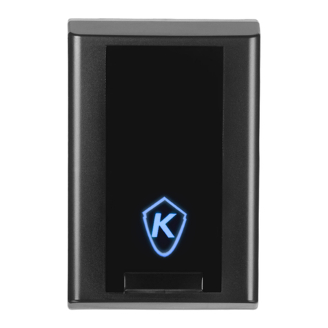
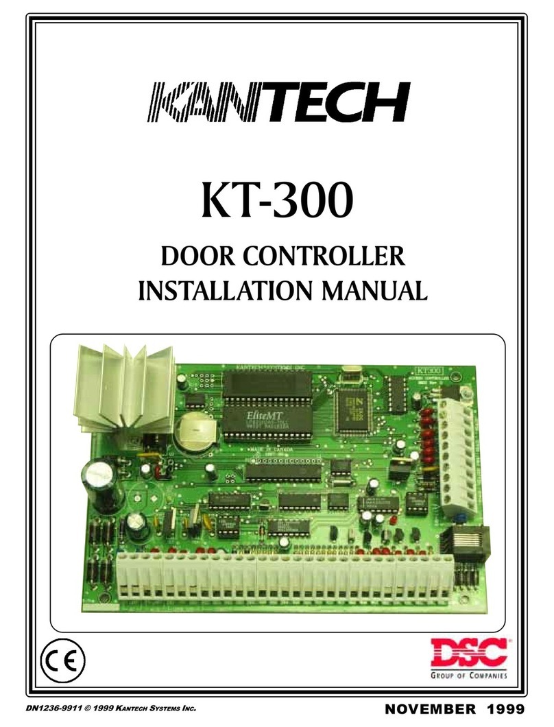
Kantech Door Controller Innovative and Powerful... User manual

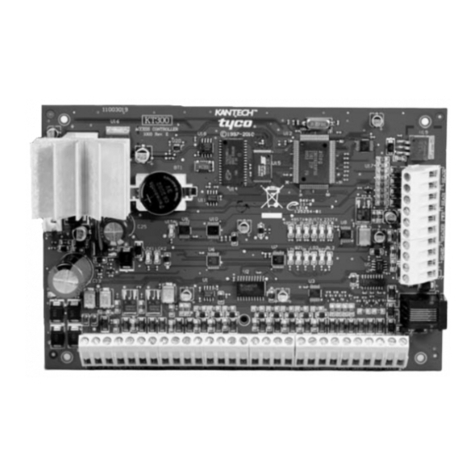
KT-300
DOOR CONTROLLER
CONTRÔLEUR DE PORTE
June / Juin 2000June / Juin 2000
June / Juin 2000
DN1315-0006 © 2000 KANTECH SYSTEMS INC.
INSTALLATION MANUAL
MANUEL D’INSTALLATION

Specifications may change at any time without prior notice.
Les spécifications sont sujettes à des modifications sans préavis.
Copyright © 1999 - 2000 Kantech Systems Inc.
All rights reserved
June 2000 / Juin 2000
DN1315-0006 • 29005115
Pourdeplusamples informations,communiquez GRATUITEMENT avecle
serviceà laclientèle deKantech.
Dulundi au vendredi de 8:00AM à 8:00PM Heure normale del’Est
Téléphone : +1 (450) 444-2040
Fax : +1 (450) 444-2029
Internet : http://www.kantech.com
Foradditional informationcall Kantech’s FREE customerassistance service.
Mondayto Friday8:00AM to 8:00PMEastern StandardTime
Phone: +1 (450) 444-2040
Fax: +1 (450) 444-2029
Internet: http://www.kantech.com
E-mail: [email protected]

i
Table of Contents / Table des Matières
Introduction to the KT-300 Door Controller 4
Technical Specifications..................................................................... 5
KT-300 and Accessories ..................................................................5
Step 1. Preparing to Install the KT-300 ............................................... 6
Step 2. Physical Installation................................................................ 6
Step 3. Power Requirements .............................................................6
Step 4. Earth Grounding..................................................................... 6
Step 5. Door Locking Devices............................................................ 7
Step 6. Hooking Up Inputs .................................................................. 7
Step 7. Readers and Keypads........................................................... 7
Step 8. Relay Controlled Outputs ....................................................... 8
Step 9. Auxiliary Outputs ...................................................................8
Step 10. Tamper Protection ................................................................ 8
Step 11. Connecting the KT-300 to the RS-485 Bus .......................... 8
Step 12. Connecting the Master Controller to the Host PC................. 8
Step 13. Powering the KT-300........................................................... 9
KT-300FCC&ICComplianceNotice .................................................. 9
KT-300CEComplianceNotice............................................................ 9
KT-300 ULCompliance Notice............................................................ 9
Electrical Specifications ..................................................................... 9
Troubleshooting CommunicationProblems......................................... 9
KT-300 Controller Maintenance Recommendations ........................... 9
Introduction to Modules .................................................................... 11
Combus Specifications .................................................................... 11
Combus Repower (If required) ........................................................ 11
Cabinet for Housing Modules ........................................................... 11
KT-PC4108 - 8-Zone Input Expansion Module ................................. 12
KT-PC4204 - 4-Relay and Additional Power Supply Module............ 13
KT-PC4216 - 16-Zone Output Expansion Module ............................ 14
KT-LCD4501 - Kantech LCD Time & Date Display Module .............. 15
Introduction au KT-300 16
Spécifications techniques ................................................................ 17
Accessoires du KT-300................................................................... 17
Étape 1. Préparation à l’installation ................................................... 18
Étape 2. Installation physique........................................................... 18
Étape3. Alimentation........................................................................ 18
Étape 4. Mise à la terre..................................................................... 18
Étape 5. Dispositifs de fermeture de porte....................................... 19
Étape 6. Connexion des entrées...................................................... 19
Étape 7. Lecteurs et claviers ...........................................................19
Étape 8. Sorties controlées par relais.............................................. 20
Étape 9. Sorties auxiliaires...............................................................20
Étape 10. Commutateur anti-sabotage .............................................20
Étape 11. Branchement du KT-300 à la voie RS-485 ....................... 20
Étape 12. Branchement du contrôleur maître à l’ordinateur .............20
Étape 13. Mise sous tension du KT-300 .......................................... 21
KT-300FCC&ICComplianceNotice ................................................ 21
KT-300CEComplianceNotice..........................................................21
KT-300 Note de conformité UL......................................................... 21
Recommandations pour l’entretien du KT-300 ................................. 21
Spécifications électriques ................................................................ 22
Ré-initialisation du KT-300 ................................................................22
Introduction aux modules ................................................................. 24
Spécifications du Combus ............................................................... 24
RéalimentationduCombus ...............................................................24
Boîtier pour la localisation des modules ...........................................24
KT-PC4108 - Module d’extension de 8 entrées................................ 25
KT-PC4204 - Module d’extension 4 relais et réalimentation .............26
KT-PC4216 - Module d’extension de 16 sorties ............................... 27
KT-LCD4501 - Afficheur LCD avec date et heure ...........................28

DN1315-0006 © 2000 Kantech Systems Inc.
KT-300 - ENGLISH INSTALLATION MANUAL
Page: 4
Introduction to the KT-300 Door Controller
Notice: The KT-300 door controller will only operate with WinPass Version 2 and EntraPass Version 3.
Innovative and Powerful
Kantech’s new KT-300 door controller is designed to meet the highest standards of access control and point
monitoring applications. The KT-300 controls 2 doors and is easily linked to a network controlling up to 512
doors.
Downloadable Firmware
The firmware program, which is stored in the controller’s flash memory, is updated without changing the
memory chips. The firmware program can be uploaded from any workstation.
Speed Selection - Fast ! Up to 115,200 Baud
The KT-300 automatically detects the loop communication speed as set at the system’s workstations.
Trouble and Reporting
The KT-300 constantly supervises battery conditions and reports “Low battery” or “No battery” status to the
system. All power outputs are supervised and individually protected against short-circuits and surges by a self-
resetting PTC. Locking devices are also supervised for short and open circuits.
Built-in Combus Expansion
The KT-300 supports expansion modulesto add inputs, outputs and an LCD time and date display for Time
& Attendance functions.
KT-PC4108 - 8-Zone Input Expansion Module KT-PC4204 - 4-Relay and Combus
AdditionalPowerSupplyModule
KT-PC4216 - 16-Output Expansion Module KT-LCD4501- LCD Time&Date Display
forTime andAttendance Functions

INTRODUCTION
DN1315-0006 © 2000 Kantech Systems Inc. Page: 5
Technical Specifications
SEIROSSECCADNARELLORTNOC003-TK
TCUDORPHCETNAK REBMUN NOITPIRCSEDTCUDORP
k821/003-TK KCOL003-TKdnaCCA003-TK,BAC003-TKgnidulcniyromemBk821htiwrellortnocrooD
k215/003-TK KCOL003-TKdnaCCA003-TK,BAC003-TKgnidulcniyromemBk215htiwrellortnocrooD
k821/BCP003-TK CCA003-TKdnaylnoBCPBk821/003-TK
k215/BCP003-TK )detsilLUton(CCA003-TKdnaylnoBCPBk215/003-TK
CCA003-TK revirdwercsdnaeriwdnuorg,revocelohkcol,sffodnatsBCP,mho021x2,mhok6.5x01,mhok0.1x2:gnidulcnitikyrosseccA
8014CP-TK 003-TKrofeludomnoisnapxetupnienoZ-8
4024CP-TK 003-TKrofeludomylppusrewoplanoitiddasubmoCdnayaleR-4
6124CP-TK 003-TKrofeludomnoisnapxetuptuO-61
1MR-TK )detsilLUton()2LR/1LR(tuptuo003-TKrofTDPSyalernoitalosilanretxE
1054DCL-TK 003-TKrofyalpsidetad&emitDCL
BAC003-TK KCOL003-TKgnidulcnitenibaclatemkcalb003-TK
BAC1504-TK ).peskcolyekredro(seludomxxxxCP-TKroftenibaclatemkcalbdradnatS
KCOL003TK )002-TKsaemas/syek2(tenibaclatemBAC1504-TK/BAC003-TKrofkcolyeK
PMAT003-TK tenibaclatemBAC1504-TK/BAC003-TKrofhctiwsrepmaT
ASC/W7361RT )detsilLUton(ASC)AV73(V61/V011,nI-eriW,remrofsnarT
ASC/P0461RT )detsilLUton(ASC)AV04(V61/V011,nI-gulP,remrofsnarT
LU/P0461RT LU)AV04(V61/V011,nI-gulP,remrofsnarT
022-W0461RT )detsilLUton(EC)AV04(V61/V022,nI-eriW,remrofsnarT
584-CV )detsilLUton(ecafretninoitacinummocnoitcnuf-itluM
16VAC, 40VA, class 2 transformer
1 battery 12 V, 7Ah, supervised, provides up to 12 hours of operation
29.9cm x 28.8cm x 7.7cm (11-3/4" x 11-3/8" x 3") EMT 1.9cm (3/4")
2,4 kg (5.4 lbs)
From 20C to 400C (350F to1100 F)
Wiegand, proximity, bar code, magnetic, integrated keypad and others
8 monitored points, NO/NC, w/without EOLs (expandable to 16)
600 meters (2,000 feet) - (AWG #22)
12VDC, 250mA max/each, supervised
4 outputs, 25mA max/each, Open collector
2 relay controlled outputs, 25mA (max) each. Open collector to ground (use
form “C”relays Kantech # KT-RM1 if needed)
12VDC @ 125mA max, protected and supervised
12VDC and 5VDC @ 175mA total, protected and supervised
RS232, RS485 and Combus
Up to 115,200 baud (automatic detection)
128k
128k (512k unit available) Protected by a lithium battery
Distributed data and processing
CE, FCC, UL294 pending
AC power ...............................................
Battery backup......................................
Cabinet measurements (H•W•D).......
Weight (with metal cabinet) ................
Operating temperatures ......................
Reader types .........................................
Monitored points ..................................
Points maximum wiring........................
Door strike power ................................
Auxiliary outputs...................................
Relay controlled outputs .....................
Auxiliary power output ........................
Reader power outputs..........................
Communication ports ...........................
Communication speeds........................
Firmware Flash memory ......................
RAM memory .......................................
Network autonomy ...............................
Certifications / Listing .........................
KT-300 and Accessories

DN1315-0006 © 2000 Kantech Systems Inc.
KT-300 - ENGLISH INSTALLATION MANUAL
Page: 6
Installers familiar with the installation can use the
checklist with the “_” symbol
Step 1. Preparing to Install the KT-300 KT-300
KT-300 KT-300
KT-300
__
__
_RequiredtoinstalltheKT-300:
• KT-300controllerwithaccessorykit
• ACtransformer 120/220VAC/16 VAC,40VA,
class 2 *
• One12voltbattery7A/h*
• Groundclamp *
A visual verification should be made when unpacking the KT-300. Any
missingitem/partordamagedcomponentshouldbereportedimmediately.
*Not included
Step 2. Physical Installation
__
__
_Checkforidealindoorlocation
__
__
_Stayawayfromelectricalorcommunicationdevices
TheKT-300controllercabinethasbeendesignedtobemountedonawall
withoutanyadditionalenclosures. Thecabinetis largeenoughtoaccom-
modate the battery backup supply and the necessary wiring connections
formostapplications.EMT(electricalmetallictubing)conduitknockouts
are provided in 2.2 cm (7/8") on all sides of the cabinet.
The cabinet should be mounted indoors, in a secure location providing
normal temperature and humidity levels, leaving 23 cm (8") clear space
aroundallsidesandaminimumof 33cm(13") clear space in front of the
cabinet.The location shouldbe easily accessible for servicing the equip-
ment and it is recommended that controllers be located close to the
controlled doors.
Controllersmustbelocatedataminimumdistanceof 2meters(6feet)from
any high voltage equipment or wiring and from electrical equipment
susceptibleofgeneratingelectricalinterference,ataminimumdistanceof
1 meter (3 feet) from telephone equipment or lines, and at a minimum of
8 meters (25 feet) from any transmitting equipment.
Physicalaccess, usingkeys,on controlleddoorsmustbe providedsothat
the KT-300 can easily be accessed for servicing purposes in case of
malfunctions.
Step 3. Power Requirements
__
__
_DONOTPOWERATTHISPOINT!
__
__
_Install 120 / 220VAC / 16VAC, 40VA, class 2 trans-
former
__
__
_Placebatteryincabinet
__
__
_DONOTPOWERATTHISPOINT!
TheKT-300controllermustbepoweredbya16VAC/40VAclass2wire-
in or plug-in transformer.
Note:Powershouldonlybeappliedtotheunitwhenallconnectionsare
completedandtested.
If the AC supply is removed, the backup 12 volt gel type of 7 Amp/hour
battery(iffullycharged)willsupportnormaloperationforupto12hours.
An internal battery verification will cut the battery power if the battery
voltage level falls below 9.5 volt.
Note: The KT-300 unit will not start on battery alone.
Step . Earth Grounding
__
__
_AWG#18groundingwireto EGND
SincetheKT-300useshighperformancecommunications,properground-
ing must be provided to ensure proper operation. An AWG#18 single
conductor solid copper wire must be used to ground each controller
to a good earth ground as per the local electrical code (be careful of
groundloops).The groundclamp should belocated belowanyother
ground.
ItisalsorecommendedtoinstallanAWG#18singleconductorcopperwire
betweeneach controller.

STEP BY STEP INSTALLATION
DN1315-0006 © 2000 Kantech Systems Inc. Page: 7
Step 5. Door Locking Devices
__
__
_Connectdoorlocksto+andLK1-(+andLK2-)
__
__
_Maximum250mA@12VDCperoutput
__
__
_Checkforlocal"magneticlock"regulations
The LK1-, LK2- and + terminals are located on the bottom left of the
KT-300 controller’s terminal strip. The locking device outputs are
controlledaccordingtotheend-userprogrammedparametersforallowing
access to or unlocking doors according to schedules and access levels.
These door locking device outputs can operate DC powered locking
devicessuchaselectromechanicalstrikesandcanbeconfiguredtooperate
infail-safeorfail-securemodes(normalorreverseaction). Themaximum
DC current for each lock output is 250mA.
Note: Use 1K ohm EOL (end-of-line resistor) between + and LK- if not
used.Thisresistorisalreadyincludedwithinthecontroller’spackagedbox
(KT300-ACC).
WARNING:Controlleddoorlocksmaybe governedbyregulatorybodies
and should always be installed according to local regulations. In most
instances, there are strict limitations to installing fail-secure devices and
fail-safelocking devices such as magnetic locks or othersimilar locking
devices on doors used as emergency exits.
Step 6. Hooking Up Inputs
__
__
_Connectdevicestoinputs1to8
__
__
_Resistors(includedwithKT-300)forall inputs5.6K
ohm(ifselected)
TheKT-300hasanon-boardcapabilityof monitoring8inputpoints(can
beexpandedto16ifKT-PC4108moduleisused). Eachinputissupervised
with orwithoutend-of-lineresistors(5.6Kohm).Themaximumdistance
ofone lineis600m(2,000 feet) withAWG#22(Kantechpart #CBL-R2).
Note: Inputscanbedefinedwith:noneorone EOLs(end-of-line)resistors
according to your EntraPass V3 or WinPass V2 software’s settings.
Inputs 1-2 are automatically reserved for the first controlled door. The
contact is assigned input 1 and the associated request-to-exit detector as
input2.Inputs3and4areautomaticallyreservedforthesecondcontrolled
door. The contact is assigned input 3 and the associated request-to-exit
detector as input 4. There is no obligation to follow these rules but such
a standard convention makes it easier for servicing.
Step 7. Readers and Keypads
READERCONNECTIONTERMINALWARNING
Connecting the red wire lead (or power lead) of a 5VDC reader to the
12VDC terminal may damage the reader. See your reader installation
procedureforproperpowerconnection.Upto2readerscanbeconnected
toaKT-300. They can be installedonone door to controlbothentry and
exit or on two separate doors operating independently to control access
in one direction only.
The distance between the readers and the KT-300 controller varies by
reader type (please consult the reader manual for details). Auxiliary
outputs provide access operation visual and/or audible feedback at the
controlled door . Outputs “OUT DOOR 1 LED & BUZ”are used for the
firstdoorand“OUTDOOR2LED&BUZ”areusedfortheseconddoor.
The12VDCauxiliarypowercanalsobeusedtopowerlowcurrentaudible
devices usually located at the controlled door.

DN1315-0006 © 2000 Kantech Systems Inc.
KT-300 - ENGLISH INSTALLATION MANUAL
Page: 8
Step 8. Relay Controlled Outputs
__
__
_Connectcontrolledoutputstolowvoltagedevices
(25mAmax)
__
__
_Addexternalrelaysforhighvoltagedevices(optional-
Kantech#KT-RM1)
TheKT-300providestwocontrolledoutputs-RL1&RL2(opencollector
toground-current limited to 25mA). Use a KT-RM1 (optional) to switch
larger currents or voltages or to supply a dry contact.
Can be expanded up to 16 controlled outputs when using a KT-PC4216
module.Thismoduleallowsamaximumof16outputsandamaximumof
upto50mA per output. Since the KT-300 onlysupports500mA,apower
supply module can be used to provide an additional 1A to the Combus.
Note: If you are using a KT-PC4204 in “repower” mode and other KT-
PC4204modules thatareassignedas relays1-4orKT-PC4216 modules
that are assigned as relays 1-16 are also connected to the same loop, do
not use relay 1 of those modules or relay 1 of the KT-300 door controller
(see page 10 for more information - Combus Repower).
Step 9. Auxiliary Outputs
__
__
_Connectauxiliaryoutputstoreaders&localwarning
devices
Auxiliary outputs are used for visual and audible signals. They can be
activated according to schedules, input conditions or events and local
alarms. Auxiliary outputs “OUT DOOR 1 & 2 LED”provide visual
feedback of access operation, and auxiliary outputs “OUT DOOR 1 & 2
BUZ”canactivateaudiblewarningdevices,suchasT.REX,tosignaldoor
alarms.
Step 10. Tamper Protection
__
__
_Installtamperswitchoncabinet-(optional-Kantech#
KT-300TAMP)
A tamper switch may be installed on the unit to detect unauthorized
opening of the cabinet (optional - Kantech part # KT-300TAMP).
The normally closed tamper switch is connected to an input (choose an
unused input (5 to 8) as tamper input or any other unused inputs on the
KT-PC4108 module (if used).
Note: The tamper switch is required for a UL listed installation.
Step 11. Connecting the KT-300 KT-300
KT-300 KT-300
KT-300 to the
RS- 85 Bus
__
__
_ConnectRS-485cabletoX1+,X1-andGND
__
__
_IfnotusingVC-485:connecta120ohmend-of-
lineresistoronthefirstandlastKT-300(X-&X+)
__
__
_IfusingVC-485:connecta120ohmend-of-line
resistoronthelastKT-300only(X-&X+)
Controllers are linked together through their RS-485 connectors. The
maximum communication loop length with the appropriate cable is 1.2
kilometers(4,000feet).ConnectingseveralKT-300controllersatasingle
point is not acceptable nor are “Y”or “spider web networks”.
TheRS-485communicationloopshouldbewiredwithEthernetCategory
3 double twisted pair network cable (see cable specifications Belden
1227Aorequivalent).TheRS-485loopcanoperatefrom1,200to115,200
baud under normal conditions.
Intermittentcommunicationproblemsorerraticoperationmayrequireto
slow down the network speed to 9,600 or 19,200 baud. Varying the
network speed does not perceptibly change the operation speed of the
system. Usually, most installations should be set at 19,200 baud.
Without a VC-485: Connect a 120 ohm end-of-line resistor between
terminals X1- and X1+ of the first and last KT-300.
With a VC-485: Connect a 120 ohm end-of-line resistor between
terminalsX1-andX1+ofthelastKT-300.Noneedtoconnectonthefirst
KT-300 since the VC-485 contains an end-of-line resistor.
Step 12. Connecting the Master Control-
ler to the Host PC
__
__
_ConnectflatcablefromtheKT-300tothePC
From 0 to 30m (0 to 100 feet):
If the local master controller is located less than 30m (100 feet) from the
hostcomputer,use the On-Board RS-232RJ12jack and the suppliedflat
cable.
From 30m to 60m (100 to 200 feet):
Since the master controller can be located up to 60m (200 feet) from the
host computer, an extra 100 feet cable can be added to the existing cable
(Kantech part no. CAB100ext).
From 60m to 1.2 km (200 to 4,000 feet):
If the master controller is located more than 60m (200 feet), an optional
VC-485multi-functioncommunicationinterfacemustbeused. Itcanalso
be used when running communications cable in areas unusually high in
electricalnoise.

STEP BY STEP INSTALLATION
DN1315-0006 © 2000 Kantech Systems Inc. Page: 9
Step 13. Powering the KT-300
__
__
_PowertheKT-300controller
After you have completed all the necessary steps, you may power
the KT-300 controller. Connect AC power and connect the battery.
Note: The KT-300 unit will not start on battery alone.
KT-300 FCC & IC Compliance Notice
This device complies with Part 15 of the FCC rules. Operation is subject
to the following two conditions: (1) this device may not cause harmful
interference, and (2) this device must accept any interference received
including interference that may cause undesired operation. This class B
digital apparatus meets all requirements of the Canadian Interference
Causing Equipment Regulations. The KT-300 is also compliant with
EN55022: 1994, amendment 1: 1995, Class B.
KT-300 CE Compliance Notice
This equipment has been tested and found to comply with the limits to
EN 50130-4: 1995.
KT-300 UL Compliance Notice
In order to comply with UL listings, the following has to be respected:
•Use of a UL listed computer
•UseofULlistedreaders(Wiegand26and34bits,magstripe26and34
bits, have been tested and found to comply)
•Use of a tamper switch on every housing cabinet for the KT-300
•Do not use a VC-485 (not UL listed)
•Do not use the SmartLink option (has not been investigated by UL)
•Use a KT-LCD4501 module on each KT-300 controller
•Do not use a 220V transformer (not UL listed)
•Use only UL listed cables
•Use only UL listed adaptors
•Use only a UL listed transformer
Note:Backupbatteryprovidesoperationofupto12hoursbuthasbeen
tested only 4 hours as per Section 33 of UL 294, fifth edition.
Note:All circuits are power limited
Electrical Specifications
VOLTAGE OUTPUTS MAXIMUM
CURRENT
ABSOLUTE
COMBINED
MAXIMUM
Lock Outputs (12 VDC) 500 mA
(250 mA each)
1.5 A
Auxiliary Power (12 VDC) 125 mA
Reader 5 VDC and 12 VDC 175 mA
Combus 500 mA
Battery Charging (12VDC) 250 mA
OPEN COLLECTOR OUTPUTS MAXIMUM
CURRENT
LED (door 1 & 2) 25 mA (each)
Buzzer (Buz, door 1 & 2) 25 mA (each)
Controlled Relay 1 & 2 (RL1 & RL2) 25 mA (each)
Troubleshooting
Communication Problems
Default Initialization:
TheKT-300defaultinitializationisdoneatKantech.Thefollowingsteps
should only be done if :
(A) Youchangedthesoftware(e.g.:youwereusingEntraPass,theninstalled
WinPass) and there’s no communication,
(B) TheKT-300wascommunicatingviatheRS-232portandyouinstalled
a VC-485 to communicate via the RS-485 port,
(C) You were using the KT-300 at a local site and now want to configure
it for remote operation.
How to use the default initialization (hard reset):
1) Disconnect the transformer and the battery,
2) Remove all connections of DOOR1 and RL1 terminals,
3) Place a jumper between the DOOR1 and RL1 terminals,
4) Apply AC power to the transformer. The VITAL LED should flash
4 times. This means that the controller is in the initialization mode,
5) Disconnect the jumper,
6) When the controller is communicating with the PC, the VITAL LED
will flash 3 beats at a time,
7) Reconnect the battery.
KT-300 Controller Maintenance
Recommendations
ItishighlyrecommendedtotesttheKT-300controllerbyperformingthe
following tests:
1) Bi-annual test for battery:
Remove AC power from the controller and connect the battery to the
controller for one hour. This test will ensure that if a power failure
occurs,the battery will be able to support normal operations. This test
should be performed twice a year. Once the test has been performed
sucessfully, reconnect AC power to the controller.
2) Annual test for emergency lithium battery:
Measurevoltageoflithiumbatterywhenpoweristotallyremovedfrom
the controller (AC & DC power). To ensure maximum operation and
prevent loss of power, if the lithium battery voltage measures below
2.5VDC, please contact your distributor to return the KT-300 for
maintenance.

DN1315-0006 © 2000 Kantech Systems Inc.
KT-300 - ENGLISH INSTALLATION MANUAL
Page: 10

STEP BY STEP INSTALLATION
DN1315-0006 © 2000 Kantech Systems Inc. Page: 11
Introduction to Modules
The Combus terminals on the KT-300 controller are used to connect
expansionmodulestoaddmoreinputs,outputs,relaysandLCDtimeand
date display. The four Combus terminals of the main panel must be
connected to the four Combus terminals or wires of all modules.
There are 4 expansion modules that can be connected to KT-300’s
Combus(morespecificationsoneachofthesemodulescanbefoundatthe
end of this document).
1) KT-PC4108 - (8 - Zone Input Expansion Module)
2) KT-PC4204 - (4 Relay/Power Supply Expansion Module)
3) KT-PC4216 - (16 - Zone Output Expansion Module)
4) KT-LCD4501 - (Kantech LCD Keypad Module)
Combus Specifications
TheCombusprovides500mAat12volt(13.85VDC).Therecommended
cableis#22 AWG (Kantech #CBL-ZN).Each loop (module toKT-300)
cannot exceed 300 m (1000') and the total maximum cable length of all
connected loops cannot exceed 1200 m (4000').
Forexample:
•Only four wireruns at 1000' from the KT-300
•Only eight wireruns at 500' from the KT-300
•Only ten (10) wireruns at 400' from the KT-300
ShieldedwireshouldonlybeusedinareasthatpresentexcessiveRFnoise
orelectromagnetic interference. Modules canbe straight run, connected
in a daisy chain or T-tapped anywhere on the Combus.
During installation of the modules, it is necessary to inform the system
that new modules have been installed on the Combus. To assign the
modules to your system (software), see your software reference manual
under “assigning modules”in the controller definition menu for detailed
information.
Combus Repower (If required)(If required)
(If required)(If required)
(If required)
Dependingonhow many modules are connected to the Combus and how
far they are from the KT-300 controller, you may need to “repower”the
controller’s Combus.
TheCombusneedstobe“repowered”ifthevoltagebetweentheblackand
red wires of the last module of each loop drops below 12.5 volt (the
moduleswillstilloperatebuttherewillbenocommunicationbetweenthe
modulesandthecontrollerandanevent“Combusmoduledefect”willbe
generatedfromthecontroller).Thisvoltagedropsifmodulesaredrawing
too much current (500mA maximum for the Combus of each KT-300).
Withamultimeter,youshouldverifythisvoltageanddetermineifyouneed
toinstallaKT-PC4204in“repower”mode.Usingthisconfiguration,you
will be provided with an additional 1 amp of current on the controller’s
Combus. The KT-PC4204 is generally installed at the beginning of the
loop.
When using the KT-PC4204 in “repower”mode, the first relay of the
modulewillbereservedforthe“repowerfunction”.Youwillhavetoassign
an “all valid”schedule to the first relay so it is “permanently activated”
(see your software reference manual in the “controller definition”menu
under “assign modules”for the exact procedure).
IfyouareusingaKT-PC4204 in “repower”mode and other KT-PC4204
modules that are assigned as relays 1-4 or KT-PC4216 modules that are
assignedasrelays1-16arealsoconnectedtothesameloop,donotuserelay
1 of those modules or relay 1 of the KT-300 door controller. Please also
note that all KT-PC4204 modules that are used for Combus repower
should be assigned as relays 1-4.
Note:Thejumper1“J1”ontheKT-PC4204mustbemovedtotheCombus
relayposition.
Note:DonotuseanypowersupplyotherthantheKT-PC4204torepower
theCombus.Intheeventofapowersurgeortransient,amodulemaylock
up and cease to communicate with the controller. If the KT-300 loses
communication with the module, it will initiate a module reset and will
powerdowntheCombusforfivesecondsinanattempttoresettheproblem
module.Afterfiveseconds,thecontrollerwillreapplypowertotheCombus
and the problem module should begin to operate as intended.
Cabinet for Housing Modules
Kantech part #: KT-4051CAB
Measurements: 16.8" H x 10.4" W x 4.1" D
Color: Black
Cabinet will hold either:
•One(1)KT-PC4204powersupply/relaymod-
ulewithbatteriesandone(1)KT-PC4108/KT-
PC4216.
•Three (3) KT-PC4216/KT-PC4108 modules

DN1315-0006 © 2000 Kantech Systems Inc.
KT-300 - ENGLISH INSTALLATION MANUAL
Page: 12
1. Introduction
TheKT-PC4108moduleisazoneinputmodulethataddsupto8fully
programmable zones to the KT-300 controller.
2. Specifications
•Connects to the controller via 4-wire Combus
•Current draw: 30 mA (from Combus)
•Supportssingleend-of-lineandnoend-of-line(5600ohmresistors)
zone loops.
•AUX+ output: 12VDC, 250mA max. (drawn from Combus)
•Tamper contact input
3. Installing the KT-PC4108 module
3.1 Unpacking
The KT-PC4108 package includes the following parts:
•One KT-PC4108 circuit board
•16 end-of-line resistors (5600 ohm)
•Four (4) plastic standoffs
3.2 Mounting
TheKT-PC4108moduleshouldbelocatedinsideacompatiblecabinet
(Kantech part no. KT-4051CAB), mounted in a dry, secure location.
Preferably, it should be placed at a convenient distance from the
connecteddevices.
Perform the following steps to mount the unit:
1. Press the four (4) plastic standoffs through the mounting holes on
the back of the cabinet.
2. Securethecabinettothewallinthedesiredlocation.Useappropriate
wallanchorswhensecuringthecabinettodrywall,plaster,concrete,
brick or any other surfaces.
3. Press the circuit board into the four (4) plastic standoffs to secure
the unit to the cabinet.
Once the unit is mounted, wiring may be started.
3.3 Installation and Wiring
Before beginning to wire the unit, ensure that all power (AC trans-
former and battery) is disconnected from the controller.
Perform the following steps to complete wiring:
1. ConnectthefourCombuswirestotheKT-PC4108.Connectthered,
black,yellowandgreenCombuswirestotheRED,BLK,YELand
GRN terminals, respectively.
2. Complete all zone wiring to the zone input terminals (Z1-Z8).
3. Connect the external tamper switch, if used.
Consult the wiring diagram above for further information.
2.4 Applying Power
Afterall wiring is completed,applypower to the controller.Connect
the battery leads to the battery, then connect the AC transformer.
Note: Do not connect the power until all wiring is complete.
4. Assigning the Module
Onceallwiringiscomplete,themodulemustbeassignedtothesystem.
To assign the module, perform the following steps:
1. Establish communication between the PC and the controller,
2. Remove the tamper switch wire,
3. A serial number should be displayed on the screen. In the same
windowwheretheserialnumberislocated,youshouldseethetype
of module and on which controller it is connected,
4. Fromthe software, select the functionality of themoduleandenter
the serial number in the appropriate field (see your software
reference manual under controller definition -- assign modules for
moredetails).
Note:Don’tforgettoreconnectthetamperswitch(orthewire,ifthere
is no tamper switch)
KT-PC 108 - 8-Zone Input Expansion Module

OPTIONAL EXPANSION MODULES
DN1315-0006 © 2000 Kantech Systems Inc. Page: 13
KT-PC 20 - -Relay and Additional Power Supply Module
1. Introduction
The KT-PC4204 module is an output module with four program-
mablerelays.Thismodulecanbeusedto“repower”theCombus.The
KT-PC4204 can also be used for elevator control.
Note: Do not use any power supply other than the KT-PC4204
moduletorepowertheCombus.IfapowersupplyotherthantheKT-
PC4204 is used, the Combus repower function will not operate as
intended.
2. Specifications
•Current draw: 30 mA (from Combus)
•40VA 16VAC transformer required
•Maximum 7A/h battery required
•Connects to the controller via 4-wire Combus
•Four programmable relay contacts rated 2A, 30VDC
•AUX current: 1.0A max.
•Tamper contact input
•Can be used to repower the Combus
3. Installing the KT-PC4204
3.1 Unpacking
The KT-PC4204 package should include the following parts/items:
•One KT-PC4204 circuit board
•One ground wire assembly
•Five plastic standoffs
•One 5A replacement fuse
3.2 Mounting
The KT-PC4204 should be located inside a compatible cabinet
(Kantechpartno.KT-4051CAB),mountedinadry,securelocation.
Preferably, it should be placed at a convenient distance from the
connecteddevices.
Perform the following steps to mount the unit:
1. Press the five plastic standoffs throughthemounting holes at back
of the cabinet,
2. Securethecabinettothewallinthedesiredlocation.Useappropriate
wallanchorswhensecuringthecabinettodrywall,plaster,concrete,
brick or other surfaces,
3. Pressthecircuitboardintotheplasticstandoffstosecurethemodule
to the cabinet.
Once the unit is mounted, wiring may be started.
3.3 Installation and Wiring
Before beginning to wire the unit, ensure that all power (AC trans-
former and battery) is disconnected from the KT-300 controller.
Perform the following steps to complete wiring:
1. ConnectthefourCombuswirestotheKT-PC4204.Connectthered,
black,yellowandgreenCombuswirestotheRED,BLK,YELand
GRN terminals, respectively,
If the module is used for Combus Repower, connect the Combus
wiresaccordingtothefollowingdiagram.Notethatforthisoption,
Jumper J1 must also be set for “Combus Relay”,
2. Complete all output wiring,
3. Connect the external tamper switch, if used.
3.4 Applying Power
After all wiring is completed, apply power to the KT-300. Connect
the battery leads to the battery, then connect the AC transformer.
Then, connect power to the KT-PC4204: the battery leads followed
by the AC transformer.
Note: Do not connect the power until all wiring is complete.
4. Assigning the Module
Once all wiring is done, the module must be assigned to the system.
To assign the module, perform the following:
1. Establish communication between the PC and the controller,
2. Remove the tamper switch wire (or only the wire if tamper switch
is not used),
3. A serial number should be displayed on the screen. In the same
window where the serial number appears, you should see the type
of module and on which controller it is connected,
4. Fromthe software, select the functionality of themoduleandenter
the serial number in the appropriate field (see your software
reference manual under controller definition -- assign modules for
moredetails),
5. If the module is used in “repower”mode, assign an “all valid”
scheduletorelay1and assign the module’sfunctionalityto “relay
1 to 4”in your software.
Note:Don’tforgettoreconnectthetamperswitch(orthewire,ifthere
is no tamper switch).
Note:EnsurethatJumperJ1issetto“CombusRelay”positionifused
as “repower”.

DN1315-0006 © 2000 Kantech Systems Inc.
KT-300 - ENGLISH INSTALLATION MANUAL
Page: 14
KT-PC 216 - 16-Zone Output Expansion Module
1. Introduction
The KT-PC4216 module is an open collector to 12 VDC 16- zone
outputmodule.Canbe used for elevator accesscontrol (mayrequire
additionalhardware).
2. Specifications
•16-outputlowcurrentmodule,12V,50mAmax.each,powerdrawn
fromCombus(since Combus can handleamaximumof 500mA, a
KT-PC4204modulein“repower”modecanbeusedtoincreasethe
current of the Combus of 1A)
•Connects to KT-300 via 4-wire Combus
•Nominal current draw of 15mA
•Tamper contact input
•Can be used for elevator control
3. Installing the KT-PC4216
3.1 Unpacking
The KT-PC4216 package should include the following parts:
•One KT-PC4216 circuit board
•4 plastic standoffs
3.2 Mounting
The KT-PC4216 should be located inside a compatible cabinet
(Kantech part no. KT-4051CAB), mounted in a dry, secure location.
Preferably, it should be placed at a convenient distance from the
connecteddevices.
Perform the following steps to mount the unit:
1. Press the four plasticstandoffsthrough the mounting holes atback
of the cabinet.
2. Securethecabinettothewallinthedesiredlocation.Useappropriate
wallanchorswhensecuringthecabinettodrywall,plaster,concrete,
brick or other surfaces.
3. Pressthecircuitboardintotheplasticstandoffstosecurethemodule
to the cabinet.
Once the unit is mounted, wiring may be started.
3.3 Installation and Wiring
Before beginning to wire the unit, ensure that all power (AC trans-
former and battery) is disconnected from the controller.
Perform the following steps to complete wiring:
1. ConnectthefourCombuswirestotheKT-PC4216.Connectthered,
black,yellowandgreenCombuswirestotheRED,BLK,YELand
GRN terminals, respectively.
2. Complete all output wiring as illustrated on this page:
3. Connect the external tamper switch, if used.
3.4 Applying Power
After all wiring is completed, apply power to the KT-300. Connect
the battery leads to the battery, then connect the AC transformer.
Note: Do not connect the power until all wiring is complete.
4. Assigning the Module
Follow the instructions below for assigning and programming your
KT-PC4216 module.
Follow these steps to assign the module(s):
1. Establish communication between the PC and the controller,
2. Remove the tamper switch wire (or only the wire if tamper switch
is not used),
3. A serial number should be displayed on the screen. In the same
windowwheretheserialnumberislocated,youshouldseethetype
of module and on which controller it is connected,
4. Fromthe software, select the functionality of themoduleandenter
the serial number in the appropriate field (see your software
reference manual under controller definition -- assign modules for
moredetails).
Note:Don’tforgettoreconnectthetamperswitch(orthewire,ifthere
is no tamper switch).
Note:Ifyouareusing aKT-PC4204in“repower” modeonthesame
loop, do not use the first relay of the KT-PC4216 (see page 10).
Note: Current is drawn
from the Combus. May
require a KT-PC4204
power supply module if
drawing too much cur-
rent from the Combus.

OPTIONAL EXPANSION MODULES
DN1315-0006 © 2000 Kantech Systems Inc. Page: 15
KT-LCD 501 - Kantech LCD Time & Date Display Module
1. Introduction
TheKT-LCD4501module is anLCD with integrated keypadwhich
presents date and time via a 32-character liquid crystal display.
2. Specifications
•Connects to control panel via 4-wire Combus
•Current draw: 50mA (from Combus)
•Inputs’status (green), AC Fail (red) and Trouble (yellow) status
lights
3. Installation
3.1 Unpacking
The KT-LCD4501 package includes the following parts/items:
•One KT-LCD4501 keypad
•Four mounting screws
2.2 Mounting
The keypad should be mounted where it is accessible to designated
pointsofentry/exit.Onceadryandsecurelocationisselected,perform
the following steps to mount the keypad:
1. Removethekeypadbackplatebylooseningthescrewlocatedatthe
base of the unit.
2. Securethekeypad’sbackplatetothewallinthedesiredlocation.Use
the included screws.
Beforemountingthekeypadtoitsbackplate,completekeypadwiring.
2.3 Wiring
Before beginning to wire the unit, ensure that all power (AC trans-
former and battery) is disconnected from the control panel.
To complete keypad wiring, connect the four Combus wires (red,
black, yellow and green) to the keypad terminals (R B Y G).
Consult the diagram below:
3.4 Applying Power
Once all wiring is complete, apply power to the controller. Connect
the battery leads to the battery, then connect the AC transformer.
Note: Do not connect the power until all wiring is complete.
3. Assigning the Keypad
Onceallwiringiscomplete,themodulemustbeassignedtothesystem.
To assign the module, perform the following steps:
1. Establish communication between the PC and the controller,
2. Press the pound key (#) on each keypad,
3. A serial number should be displayed on the screen. In the same
window where the serial number is displayed, you should see the
type of module and on which controller it is connected,
4. Fromthesoftware,selectthefunctionalityoftheKT-LCD4501and
enter the serial number in the appropriate field (see your software
referencemanualundercontrollerdefinition--Assigningmodulesfor
moredetails).

DN1315-0006 © 2000 Kantech Systems Inc.
KT-300 - MANUEL D INSTALLATION
Page: 16
Introduction au KT-300
Note : Le contrôleur de porte KT-300 n’est compatible qu’avec les logiciels WinPass Version 2 et
EntraPass LS / RS Version 3.
Puissant et innovateur
Le contrôleur de porte KT-300 a étéconçu dans le but d’atteindre les plus hauts standards d’applications de contrôle
d’accès et de supervision. Le KT-300 contrôle jusqu’à deux (2) portes et il peut être facilement reliéàun réseau
contrôlant jusqu’à 512 portes.
Mise à jour du microprogramme
Lemicroprogramme,localisédanslamémoirevive(Flash)ducontrôleur,estmisàjourdirectementàpartird’unposte
de travail du système.
Rapide! Jusqu’à 115 200 bauds
Le KT-300 détecte automatiquement la vitesse de transmission des données de la boucle telle que spécifiée au poste
detravail.
Détection des defectuosités
LeKT-300 supervise continuellement la condition de la batterie et rapporte au système les événements «Batterie faible »
et «Aucune batterie ». Toutes les sorties d’alimentation sont protégées individuellement contre les courts-circuits
et les surtensions par le biais d’un fusible àréenclenchement automatique (parasurtenseur). Les composantes de
verrouillage sont également supervisées par le contrôleur contre les circuits ouverts ou fermés.
Extension Combus intégrée
Le contrôleur de porte KT-300 peut supporter différents modules d’extension d’entrées, de sorties ainsi qu’un
afficheur LCD pour fonctions de temps et présence.
KT-PC4108 - Module de 8 entrées KT-PC4204 - Module de 4 relais
et réalimentation du Combus
KT-PC4216 - Module de 16 sorties KT-LCD4501 - Module à affichage LCD
Temps et présence

INTRODUCTION
DN1315-0006 © 2000 Kantech Systems Inc. Page: 17
Alimentation primaire ........................
Batterie d’urgence .............................
Dimensions du boîtier cm (pc)..........
Poids (avec boîtier de métal) ............
Températures d’opération ................
Technologies de lecture ....................
Points surveillés (inputs)...................
Distance maximale des points ..........
Alimentation des gâches ...................
Sorties auxiliaires (DEL, BUZ) ........
Sorties auxiliaires ...............................
Sorties d’alimentation lecteurs.........
Ports de communication ....................
Vitesse de communication ................
Mémoire microprocesseur ...............
Mémoire RAM ...................................
Autonomie du réseau .........................
Certifications .......................................
Spécifications techniques
Accessoires du KT-300
16 VCA @ 40VA, transformateur de classe 2
12 VCC, 7Ah, supervisée, jusqu’à 12 heures d’opération
29,9 H x 28,8 L x 7,7 P (11-3/4" H x 11-3/8" W x 3" D) EMT 1,9 (3/4")
2,44 kg (5.4 lbs)
De 20C à400C (350F à1100 F)
Wiegand, proximité, code àbarre, magnétique, clavier intégré
8 points de surveillance, N.O./N.F., avec/sans résistances de fin de ligne
(extensible à16)
600 mètres (2,000 pieds) - (AWG #22)
12VCC, 250mA max/chacune, supervisées
4 sorties supervisées, 25mA max/chacune. collecteur ouvert
12VCC @ 125mA max, protégées et supervisées
12VCC @ 175mA total, protégées et supervisées
RS232, RS485 et Combus
Jusqu’à 115200 bauds (détection automatique)
128kB
128kB (unitéde 512kB disponible) protégée par batterie au lithium
Distribution et traitement des données
CE, FCC, UL294 en attente
SERIOSSECCATESÈCCA'DRUELÔRTNOC003-TK
EDORÉMUN HCETNAKTIUDORP TIUDORPUDNOITPIRCSED
k821/003-TK KCOL003-TKteCCA003-TK,BAC003-TKtnaulcnieriomémedBk821cevasècca'druelôrtnoC
k215/003-TK KCOL003-TKteCCA003-TK,BAC003-TKtnaulcnieriomémedBk215cevasècca'druelôrtnoC
Bk821/BCP003-TK CCA003-TKte)tnemeluesBCP(eriomémedBk821cevasècca'druelôrtnoC
Bk215/BCP003-TK )LUéifitrecnon(CCA003-TKte)tnemeluesBCP(eriomémedBk215cevasècca'druelôrtnoC
BAC003-TK KCOL003-TKtnaulcnirionlatémedreitîoB
CCA003-TK edlif,erurreseduortedelcrevuoc,egaveledsdeip,smho021x2,smhoK6.5x01,smhoK0.1x2:seriosseccA sivenruotteerretalàesim
KCOL003TK )002-TKeuqemêm/sélc2(BAC1504-TKteBAC003-TKsreitîobruoperurreS
PMAT003-TK BAC1504-TKteBAC003-TKsreitîobruopegatobas-itnaruetatummoC
8014CP-TK 003-TKruop)stupni(seértne8ednoisnetxe'deludoM
4024CP-TK 003-TKelruopnoitatnemila-ér/sialer4ednoisnetxe'deludoM
6124CP-TK 003-TKruopseitros61ednoisnetxe'deludoM
1054DCL-TK 003-TKruoperuehteetadceva)DCL(sediuqilxuatsircedegahciffaàreivalC
BAC1504-TK )tnemérapéserurresrednammoc(-xxxxCP-TKseludomruoprionlatémedreitîoB
1MR-TK )LUéifitrecnon(003-TKud2LR/1LRseitrosruop)TDPS(ruesrevnitcatnocelpmisàsialeR
ASC/W7361RT )LUéifitrecnon(ASC)AV73(V61/V011,)nI-eriW(redroccaràACruetamrofsnarT
ASC/P0461RT )LUéifitrecnon(ASC)AV04(V61/V011,)nI-gulP(rehcifneàACruetamrofsnarT
LU/P0461RT LU)AV04(V61/V011,)nI-gulP(rehcifneàACruetamrofsnarT
022-W0461RT )LUéifitrecnon(EC)AV04(V61/V022,)nI-eriW(redroccaràACruetamrofsnarT
584-CV )LUéifitrecnon(snoitcnofitlumnoitacinummocedecafretnI

DN1315-0006 © 2000 Kantech Systems Inc.
KT-300 - MANUEL D INSTALLATION
Page: 18
L’installateur familier avec l’installation peut utiliser le
guide rapide identifié du symbole «_»
Étape 1. Préparation à l’installation
__
__
_Composantesrequisespourl’installationduKT-300
•ContrôleurKT-300avecensembled’accessoires
•Transformateur 120/220VCA/16VCA@40VA,
classe 2 *
•Une(1)batterie12volts7A/h*
•Un(1)collierde mise àla terre *
EndéballantlecontenudelaboîtecontenantleKT-300,assurez-vousque
toutes les composantes sont présentes et qu’elles ne sont pas endomma-
gées.Sidescomposantesmanquentousontabîmées,veuillezeninformer
votre distributeur immédiatement.
* Non inclus
Étape 2. Installation physique
__
__
_Repérerl’endroitidéalpourl’installation
__
__
_Éloignerl’installationdetoutappareilélectriqueou
decommunications
LeboîtierdemétalducontrôleurKT-300(Kantech# KT-300CAB)aété
conçu pour une installation en surface. De ce fait, sa taille permet de
contenirlabatteried’urgenceainsiquelesconnexionsdecâblagenécessai-
res pour la majoritédes applications.
Le boîtier possède des ouvertures amorcées de conduit sur tous les côtés
de2,2 cm (7/8”). Le boîtier doit êtreinstalléàl’intérieur, dansun endroit
sec et sécuritaire, oùla température et l’humiditésont normales et qui
permetégalementunepriseàlaterre,desorteàlaisser23cm(8”)d’espace
libre tout autour du boîtier et au moins 33 cm (13”) d’espace devant le
boîtier.
On doit pouvoir facilement accéder au boîtier pour l’entretien de l’équi-
pement. Il est d’ailleurs recommandéd’installer les contrôleurs près des
portes contrôlées, àune distance d’au moins 2 mètres (6 pieds) de tout
dispositifélectrique susceptible de causerdesinterférences,àaumoins 1
mètre(3pieds)detoutappareiloulignetéléphoniqueetàaumoins8mètres
(25 pieds) de tout équipement de transmission.
Étape 3. Alimentation
__
__
_NEBRANCHERPASL’ALIMENTATIONÀCETTE
ÉTAPE-CI!
__
__
_Installerletransformateurde classe 2, 120 / 220VCA/
16VCA@40VA
__
__
_Placerlabatteriedansleboîtier
__
__
_NEBRANCHERPASL’ALIMENTATIONÀCETTE
ÉTAPE-CI!
Le contrôleur KT-300 doit être branchéàun transformateur 16VCA/
40VA.
Note : Il ne faut pas alimenter avant que toutes les connexions soient
complétéesettestées.
Si l’alimentation C.A. est coupée, la batterie d’urgence (si pleinement
chargée) àelle seule peut assurer un fonctionnement normal jusqu’à 12
heures durant. Lorsque l’énergie fournie par la batterie d’urgence chute
sous 9.5 volts, un dispositif interne cessera l’alimentation du courant.
Note : Le KT-300 ne peut démarrer avec les batteries. Au départ, il est
nécessaire de brancher le courant alternatif.
Étape . Mise à la terre
__
__
_UtiliseruncâbledecalibreAWG#18pourlamiseàla
terre-EGND
PuisqueleKT-300requiertunecommunicationàhautrendement,unemise
àla terre adéquate est indispensable pour assurer le bon fonctionnement
du contrôleur.
Pour ce faire, utiliser un câble unifilaire de cuivre AWG#18 et
brancher chaque contrôleur àune mise àla terre conformément au
code électrique local. Si d’autres mises àla terre sont branchées au
mêmeendroit,le collierduKT-300 doit êtrefixédefaçon àprécéder
les autres mises àla terre.
Ilestégalementrecommandédebrancherlescontrôleurl’unàl’autreàl’aide
d’un autre câble unifilaire de cuivre AWG#18.

INSTALLATION ÉTAPE PAR ÉTAPE
DN1315-0006 © 2000 Kantech Systems Inc. Page: 19
Étape 5. Dispositifs de fermeture de
porte
__
__
_Brancherlesdispositifsdefermeture sur les bornes +
etLK1-(+etLK2-)
__
__
_Maximum250mA@12VCCparsortie
__
__
_Consulterlesréglementationsenvigueurenmatière
desystèmesautomatiquesdefermeturedeporte
LesbornesLK1-,LK2-et+sontsituéesen bas àgauche du KT-300. Ces
sorties sont contrôlées par le biais de paramètres propres aux utilisateurs
finauxdanslebutdepermettrel’accèsoul’ouverturedesportesàcertaines
heuresspécifiées(horairesetniveauxd’accès).Cessortiespourdispositifs
de verrouillage de porte peuvent régir des dispositifs de verrouillage de
portefonctionnantsoustensionCC;telsquelesventousesélectromagné-
tiques qui peuvent être programmées pour fonctionner soit en mode «à
l’épreuve des pannes (fail-safe)»ou par «fermeture en cas de panne de
courant(fail-secure)»(actionnormaleouinversée).Latensionmaximale
permise pour chaque sortie est de 250 mA.
Note:Utiliser une résistance definde ligne de 1Kohmsentre les bornes
+etLK-siellesnesontpasutilisées.Cesrésistances(2)sontinclusesdans
l’ensemble d’accessoires compris avec le contrôleur (KT300-ACC).
AVERTISSEMENT: Il est probable que les dispositifs de verrouillage
de porte fassent l’objet de réglementations. Dans la plupart des cas, des
règlesstrictesrégissentl’installationde ventousesélectromagnétiqueset
autres dispositifs similaires sur des portes de sortie.
Étape 6. Connexion des entrées
__
__
_Brancher les dispositifs sur les bornes 1 à8
__
__
_Résistances(inclusesavecKT-300)pourtoutesles
entréesde5.6Kohms(sirequis)
LeKT-300estconçupourpouvoircontrôler8pointsd’entrée(extensible
à16 avec le module KT-PC4108). Chaque point d’entrée est supervisé
avecousansrésitancedefindeligne(5.6Kohms).Ladistancemaximale
decâblaged’unpointestde600m(2000`)enutilisantuncâbledecalibre
AWG#22 (Kantech #CBL-R2).
Note : Les points d’entrées peuvent être définis soit avec aucune ou une
seule résistance de fin de ligne selon les paramètres de votre logiciel
EntraPass V3 ou WinPass V2, (veuillez vous référer au diagramme de
câblage pour l’installation des résistance de fin de ligne).
Les bornes 1 et 2 sont principalement réservées pour la première porte
surveillée:lecontactbranchésurlaborne1etledétecteurdedemandede
sortie(REX)surlaborne2.Lesbornes3et4sontprincipalementréservées
pour la deuxième porte surveillée : le contact branchésur la borne 3 et le
détecteur de demande de (REX) sortie sur la borne 4. Si cette pratique ne
constituepasunenormeobligatoire,elleenfacilitegrandementlamainte-
nance.
Étape 7. Lecteurs et claviers
AVERTISSEMENTDEBRANCHEMENTD’UNLECTEUR:
Le branchement par un fil conducteur rouge d’un lecteur de 5VCC àune
borne 12VCC peut endommager le lecteur. Consulter la procédure
d’installation du lecteur pour connaître la tension d’alimentation de ce
dernier. Chaque KT-300 peut supporter 2 lecteurs. Ces dispositifs de
contrôle d’accès peuvent être installés sur une même porte pour en
contrôlerl’entréeet la sortie, ou sur deux portes différentes,indépendan-

DN1315-0006 © 2000 Kantech Systems Inc.
KT-300 - MANUEL D INSTALLATION
Page: 20
tes, et ne contrôler que l’accès dans un sens (un détecteur de demande de
sortie peut être installéde l’autre côtépour contrôler la sortie).
La distance entre les lecteurs et le KT-300 peut varier selon le type de
lecteur (consulter les instructions du lecteur pour plus de détails).
Lessortiesauxiliairesdeslecteurssontutiliséespoureffectueruncontrôle
visuel et audible des portes contrôlées. Les sorties OUTDOOR 1 DEL
(indicateurd’état)& BUZ (bruiteur) sont utilisées pour la première porte
tandis que les sorties OUTDOOR 2 DEL (indicateur d’état) & BUZ
(bruiteur) sont utilisées pour la seconde porte. La sortie auxiliaire de
12VCC peut être utilisée pour des dispositifs audibles, àbasse tension,
généralement situés aux portes controlées.
Étape 8. Sorties controlées par relais
__
__
_Brancher les relais aux sorties RL1 et RL2 (basse
tension25mAmax.)-(optionnel-Kantech#KT-RM1)
__
__
_Ajouterdesrelaisauxdispositifsdehautetension
Le KT-300 fournit deux (2) sorties relais (RL1 & RL2) de 25mA/ch.
(collecteur ouvert àla masse). Utiliser un relais de forme «C »KT-RM1
(optionnel)danslebutd’augmenterlatensiondesortieousimplementde
contrôler les sorties àl’aide de contacts secs.
Jusqu’à16sortiescontrôléespeuventêtreajoutéesaucontrôleurKT-300
enutilisantunmodulede typeKT-PC4216.Lorsqu’ajoutéaucontrôleur,
ilajouteraunmaximumde50mAparsortie.Puisquelecontrôleurnepeut
supporterque500mA,unmodulederéalimentationKT-PC4204peutêtre
utilisépourajouterunetensionsupplémentairede1AsurleCombus(voir
page 11 & 13 pour plus d’information).
Note : Si vous utilisez un KT-PC4204 en mode «réalimentation», et que
d’autres modules KT-PC4204 sont assignés à la fonctionnalité «relais 1
à 4»oudesmodulesKT-PC4216quisontassignéslafonctionnalité«relais
1 à 16» dans votre logiciel de contrôle des accès et qu’ils sont branchés
sur la même boucle, n’utilisez pas le premier relais (relais no.1) de ces
derniers ni le relais 1 du KT-300 (voir la page 11 pour plus de détails -
réalimentationcombus).
Étape 9. Sorties auxiliaires
__
__
_Brancherlessortiesauxiliairesaux dispositifs de
lectureoud’alarme
Lessortiesauxiliairessontutiliséespour uneretransmissiondesétatsdes
accès (audible et visuel). Pour visualiser l’état des accès, brancher les
sortiesOUT DOOR 1& 2 DEL auxvoyants lumineux DELdes lecteurs.
Pouractiverouobtenirunsignalaudible,brancherlessortiesOUTDOOR
1 & 2 BUZ aux lecteurs ou tout autre dispositif d’alarme audible tel que
le T.REX pour signaler une alarme de porte.
Étape 10. Commutateur anti-sabotage
__
__
_Installerlecommutateuranti-sabotagedansleboîtier
duKT-300(optionnel-Kantech#KT-300TAMP)
Uncommutateuranti-sabotagepeut être installésur le boîtier du KT-300
(Kantech#KT-300TAMP)danslebutdedétectertoutetentatived’ouver-
ture.Normalementenpositionfermée,lecommutateurdoitêtreraccordé
aux bornes (choisir une borne disponible (5 à8) ou toute autre borne
disponible sur le module KT-PC4108 (si utilisé).
Note:L’utilisation d’un commutateur anti-sabotage est requispourque
l’installationsoitcertifiéeUL.
Étape 11. Branchement du KT-300KT-300
KT-300KT-300
KT-300 à la
voie de communication RS- 85
__
__
_BrancherlecâbleRS-485auxbornesX1+etX1-et
EGND
__
__
_SansVC-485 :brancherunerésistance defindeligne
de120ohmsentrelesbornesX1+etX1-dupremieret
dernierKT-300(incluseavecKT-300ACC)
__
__
_AvecVC-485:brancherunerésistancedefindeligne
de120ohmsentreles bornesX1+etX1-du dernier
KT-300(incluseavecKT-300ACC)
Lescontrôleurscommuniquententreeuxviaunevoiedecommunication
RS-485. Sonimmunitéauxinterférencesestélevéeet,silecâbleapproprié
estutilisé,laboucledecommunicationpeutatteindrejusqu’à1.2kilomè-
tres (4000 pieds) de long. Le branchement de plusieurs KT-300 sur un
même point et la disposition en forme de «Y»ou en réseau type «toile
d’araignée»est inapproprié.
Pour une communication RS-485 optimale, il est recommandéd’utiliser
un câble de communication de type : Ethernet catégorie 3, fils appariés
et torsadés, non blindé, de calibre 24, (Belden # 1227A de préférence -
Kantech# CBL-ETHG3). La vitessedecommunicationdelaboucle RS-
485peutalleràundébitde1,200à115,200bauds.Toutefois,ilestprobable
que des problèmes d’intermittence ou d’erreurs d’opérations nécessitent
une réduction de la vitesse du réseau à9,600 ou à19,200 bauds.
Laréductiondelavitessen’affecterapaslavitessed’opérationdusystème
de façon perceptible. La plupart des installations devraient fonctionner
sans problème à19,200 bauds.
Note Importante :
SANSVC-485:Brancherunerésistancedefindelignede120ohmsentre
les bornes X1- et X1+ du premier et du dernier KT-300.
AVECVC-485:Brancherunerésistancedefindelignede120ohmsentre
lesbornesX1-etX1+dudernierKT-300seulement.Iln’estpasnécessaire
sur le premier puisque le VC-485, qui est installéau début d’une boucle,
contient une résistance.
Étape 12. Branchement du contrôleur
maître à l’ordinateur de gestion
__
__
_RelierlecâbleplatduKT-300àl’ordinateurdegestion
Distancesdecâblage :
De 0 à30 mètres (0 à100 pieds) :
Sile contrôleur local maîtreestsituéàmoins de 30 mètres(100 pieds) de
l’ordinateurdegestion,brancherlecâblede30mètres(100pieds)àla prise
RS-232/RJ12située sur lecontrôleur (voir diagrammede branchement).
De 30 à60 mètres (100 à200 pieds) :
Puisque le contrôleur maître peut être localiséjusqu’à 60 mètres (200
pieds) de l’ordinateur de gestion, un câble optionnel de 30 mètres (100
pieds) doit être ajoutéau câble existant (Kantech # CAB100EXT).
De 60 mètres à1.2 km (200 à4000 pieds) :
Si le contrôleur maître est situéàplus de 60 mètres (200 pieds) de
l’ordinateur de gestion, un convertisseur de protocole (VC-485) RS-232
/ RS-485 est requis. Il peut aussi être utilisélors de câblage de communi-
cations dans un endroit exceptionnellement élevéen interférence.
Pour les instructions de branchement, consulter le diagramme suivant.
Other manuals for Door Controller Innovative and Powerful...
3
Table of contents
Languages:
Other Kantech Controllers manuals

Kantech
Kantech KT-1 User manual

Kantech
Kantech Door Controller Innovative and Powerful... User manual

Kantech
Kantech IoPass SA-500 User manual

Kantech
Kantech KT-1 User manual

Kantech
Kantech KT-NCC User manual

Kantech
Kantech KT-1 User manual

Kantech
Kantech Door Controller Innovative and Powerful... User manual

Kantech
Kantech KT-315 User manual

Kantech
Kantech Door Controller Innovative and Powerful... User manual

Kantech
Kantech KT-NCC User manual