Karma PAA 460 User manual

User's Manual
PROFESSIONAL PUBLIC ADDRESS AMPLIFIER
PROFESSIONAL
PUBLIC
ADDRESS
AMPLIFIER
NF00137
0 10 0 10 0 10 0 10 0 10
0 10 0 10 0 10
0 10
0 10 0 10
INP UT 1 IN PUT 2 I NPUT 3 INP UT 4 IN PUT 5 AU X ZON E 1 ZON E 2
ZON E 1 ZON E 2MON ITOR
BASS TREB LE TREB LE
BASS T REBLE
BASS BASS T REBLE T REBL E
BASS LEVEL
-10 +1 0 -10 +1 0 -10 +1 0 -10 +10 -1 0 +10 -10 +10 -10 +1 0 -10 +10 -1 0 +10 -10 +10
ZONE 1 ZONE 2
ZONE 1 ZONE 2 ZONE 2
ZONE 1 ZONE 2
ZONE 1 ZONE 2
ZONE 1
ZONE 3 ZONE 4 ZO NE 3 ZONE 4 ZONE 4
ZONE 3 ZONE 4
ZONE 3 ZONE 4
ZONE 3
LEVE L LEVE L LEVEL LEVE L LEVEL
MUTEMUTEMUTEMUTEMUTE L EVEL LEVEL LEVE L MONMON
MONMO N LEVELLEVE L
POW ER

1
CAUTION
RISK OF ELECTRIC SHOCK
DO NOT OPEN
SAFETY INSTRUCTIONS
Describes precautions that should
be observed to prevent damage to
the apparatus.
CAUTION:
The symbol is used to indicate that
some hazardous live terminals are
involved with in this apparatus,
even under the normal operating
conditions.
The symbol is used in the service
documentation to indicate that
specific component shall be only
replaced by the component spec-
ified in that documentation for
safety reasons.
Protective Ground Terminal
AC mains (Alternating Current)
Hazardous Live Terminal
ON:
OFF:
Denotes the apparatus turns on.
Denotes the apparatus turns off,
because of using the single pole
switch, be sure to unplug the AC
power to prevent any electric shock
before you proceed you service.
WARNING:
Describes precautions that should
be observed to prevent the danger
of injury or death to the user.
Disposing of this product should not
be placed in municipal waste and
should be separate collection.
WARNING
Ensure the source voltage matches the
voltage of the power supply before turning
ON the apparatus.
Unplug this apparatus during lightning
storms or when unused for long periods
of time.
Power supply
The external wiring connected to the out-
put hazardous live terminals requires
installation by an instructed person, or
the use of ready-made leads or cords.
There are maybe some are as with high
voltages inside, to reduce the risk of el-
ectricshock, do not remove any cover if
the power supply is connected,
Do not Remove any Cover
External Connection
The cover should be removed by the qual-
ified personnel only.
No user serviceable parts inside.
To prevent a fire, make sure to use fuses
with specified standard (current ,voltage,
type). Do not use a different fuse or short
circuit the fuse holder.
Before replacing the fuse, turn OFF the
apparatus and disconnected the power
source.
Fuse
Make sure to connect the protective
grounding to prevent any electric shock
before turning ON the apparatus.
Never cut off the internal or external pro-
tective grounding wire or disconnect the
wiring of protective grounding terminal.
Protective Grounding
8
29. THE MIC/LINE INPUT CONNECTOR.
These are the channels from Channel1 to Channel3. You can connect balanced, low impedance
microphones to the XLR socket. On the 1/4" phone jack you can connect either a microphone
or a line level instrument. You shall never connect an unbalanced microphone lt the XLR socket
if you do not want to damage both the Microphone and the Mixer.
TECHNICAL SPECIFICATION
OUTPUT POWER CAPACITY RMS: 60W x 4
AC: 110-120V 50/60Hz
AC: 220-240V 50/60Hz
FREQUENCY RESPONSE 50Hz~18KHz (±3dB)
MIC : -50dB
AUX : -18dB
INPUT SENSITIVITY
BASS: ±10dB (100Hz)
TREBLE: ±10dB (10KHz)
<0.5%
MIC≥65dB
AUX ≥75dB
MIC LEVEL CONTROL
AUX LEVEL CONTROL
TONE CONTROL (BASS, TREBLE)
AC SWITCH
PHONE CONTROL
MONITOR CONTROL
EACH CHANNEL HAS THE INPUT LEVEL CONTROL
4Ω, 8Ω
50V,70V, 100V
YES
YES
YES
YES
420X342X133mm
TONE CONTROLS
OUTPUT IMPECANCE
LINE OUTPUT
CHIME FUNCTION
VU-METER (LED)
TELPHONE PAGING LELECT FUNCTION
INPUT 1 PRIORITY
DIMENSION
SIGNNAL /NOISE RATIO
TOTAL HARMONIC DISTORTION
POWER SUPPLY
CONTROLS
LINE : -17dB
TEL. : -30dB

2
Read these instructions
Follow all instructions
Keep these instructions
Heed all warnings
Only use attachments / accessories
specified by the manufacturer
Power cord and plug
Do not defeat the safety purpose of
the polarized or grounding type plug.
A polarized plug has two blades with
one wider than the other. A grounding
type plug has two blades and a third
grounding prong. The wide blade or
the third prong are provided for your
safety. If the provided plug does not fit
into your outlet, consult an electrician
for replacement of the obsolete outlet.
Protect the power cord from being
walked on or pinched particularly at
plugs, convenience receptacles, and
the point where they exit from the
apparatus.
Cleaning
When the apparatus needs a cleaning, you
can blow off dust from the apparatus with
a blower or chean with rag etc.
Don't use solvents such as benzol, alcohol,
or other fluids with very strong volatility and
flammabibity for cleaning the apparatus
body, Clean only with dry cloth.
Servicing
Refer all servicing to qualified personnel, To
reduce the risk of electric shock, do not per-
form any servicing other than that contained
in the operating instructions unless you are
qualified to do so.
Servicing is required when the apparatus has
been damaged in any way, such as power
supply cord or plug is damaged, liquid has
been spilled or objects have fallen into the
apparatus, the apparatus has been exposed
to rain or moisture, does not operate
normally or has been dropped.
IMPORTANT SAFETY INSTRUCTIONS
This apparatus shall not be exposed
to dripping or splashing and that no
objects filled with liquids, such as
vases, shall be placed on this apparatus.
To reduce the risk of fire or electric
shock, do not expose this apparatus
to rain or moisture.
Do not use this apparatus near water.
Install in accordance with the manuf-
acturer's instructions, Do not install
near any heat sources such as radiators,
heat registers, stoves, or other apparatus
(including amplifiers) that produce heat.
Do not block any ventilation openings.
No naked flame sources, such as lighted
candles, should be placed on the apparatus.
Operating Conditions
7
PRI ORITY
G
R
T
TEL .PAGIN G
MON ITOR
Lin e out 1 W
8
MON ITOR
+ +
19 20 21 22
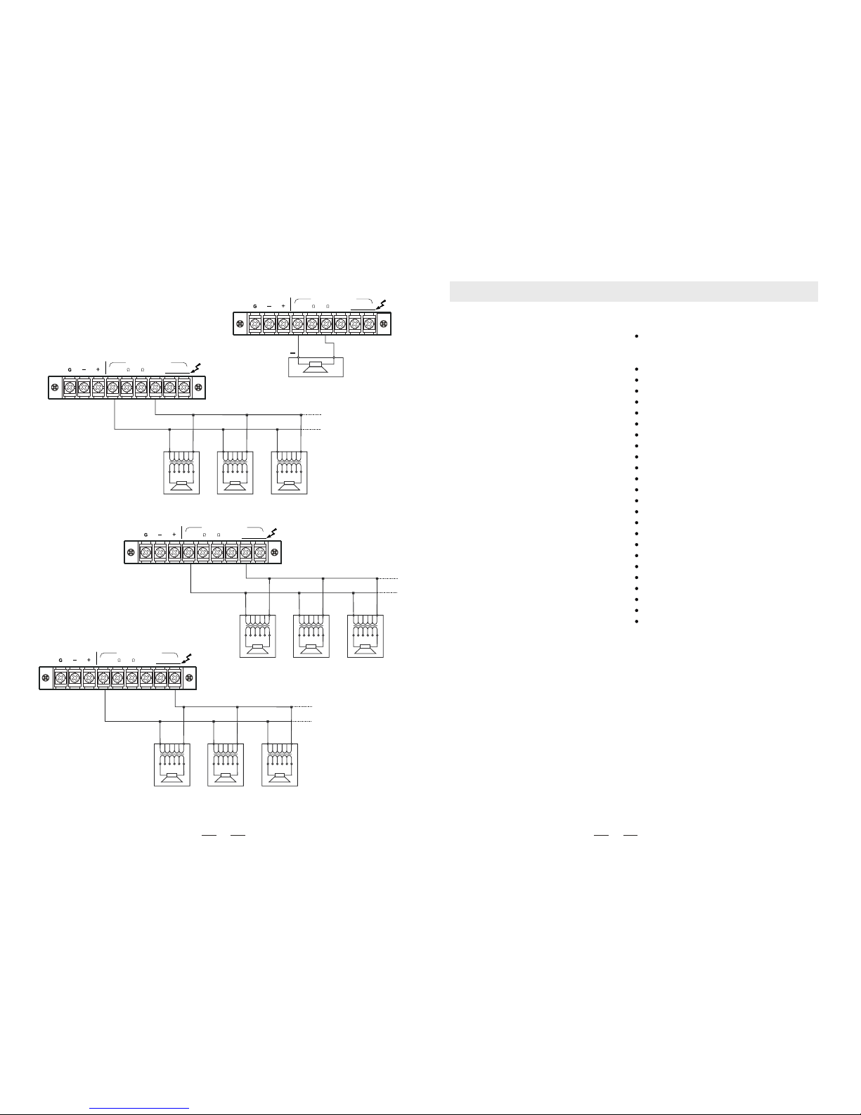
19. MONITOR LINE OUT
Monitor Line Out can be connected with other appliance, such as amplifier, recorder, etc.
20. MONITOR 1W/8
The terminal is meant for the connection of a small external
loudspeaker that gets driven by an internal auxiliary power
amplifier, providing a nominal output 1Watt. Only the mixed
audio signal coming from "AUX IN" are included in the outp-
utted signal. In addition, the output signal is controlled only by the volume control of the "CH4",
"CH5", music signal level control.
21. "PRIORITY" TERMINAL.
When these terminals are short-circuited (i.e. By means of using an electrical switch), the audio
signals coming from "CH4", "CH5", are attenuated while the signals coming from"CH1", "Ch2",
"CH3" are gaining priority.
22. INPUT "AUX PAGING"
The terminals input lets you connect to an auxiliary signal . The input features "Voice Priority"
function, which overrides all other input signals once, an auxiliary message is sent. If you want
to have this function disabled forever, please contact a distributor.
CH 4 CH 5
GAI NGAI N
TEL
ZON E
LEV EL
1 2 3 4
ON DIP
CH 1
LINE PH. MIC GAIN
23
24
2526
27 28
29
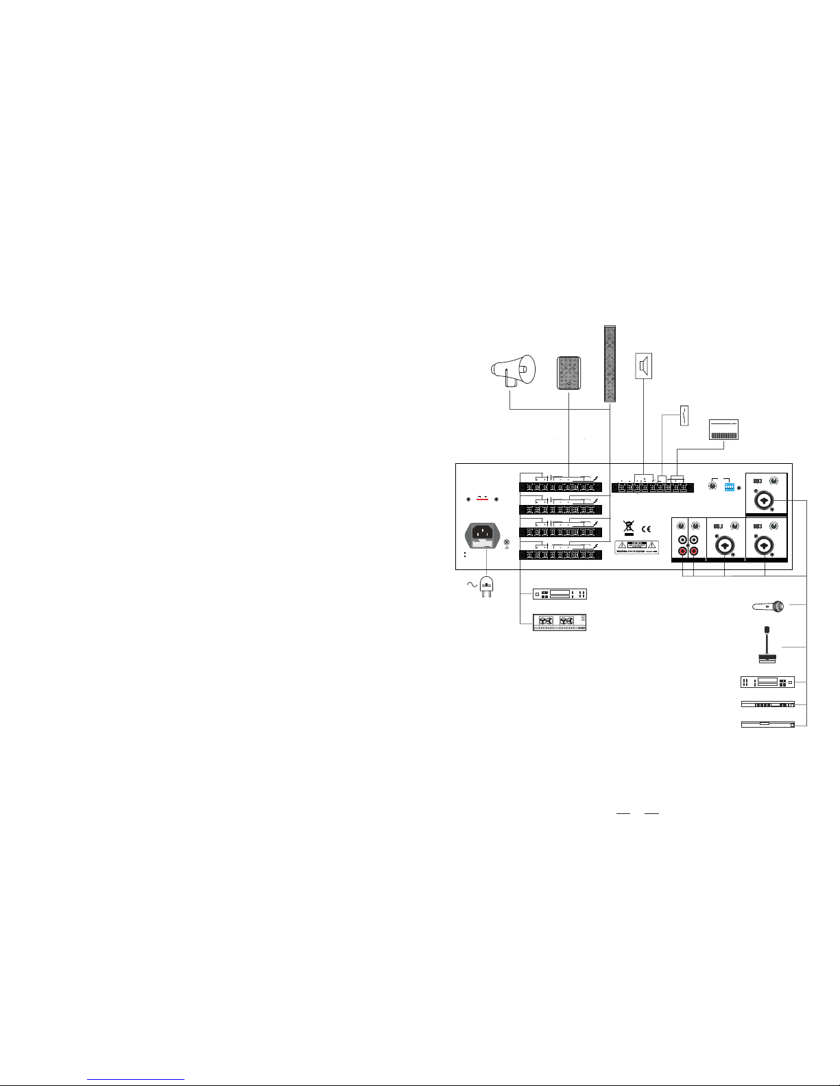
23. CH5/CH4 GAIN CONTROLLER
It can a just the level of the CH5/CH4 input.
24. ''LINE IN" INPUTS
An audio source with a high level output signal, such as an AM/FM tuner , a
cassette deck, a CD player, etc. Use input sensitivity switch suitable for difference appliances.
They are able to take RCA-type coaxial connectors, and unbalanced signals.
25. TEL. IN ZONE SWITCHES
There are four dip switches here. Push the dip switch up, it switches off and
vice versa and can assign the input to different zone.
26. LEVEL
It can adjust the level of the TEL. input.
27. CH1, CH2, CH3 AND INPUTS SENSITIVITY AND XLR PHANTOM SWITCH
By turning the switch onto the "LINE" position the CH1, Ch2, Ch3 input
can be connected to an audio source with high level signal output. By
turning these switches onto the MIC position, CH1, CH2, Ch3 input can
be connected to a dynamic microphone with low impedance. By turning
the switch onto the "Phantom" position it connects phantom supply for
XLR pin2 and pin3 of CH1, CH2, Ch3, which is necessary to operate condenser microphone
which requires this type of external supply. It is recommended to use this switch with the ge-
neral volume set on minimum.
28. GAIN
It is adjust the level of the inputs.

3
GENERAL DESCRIPTION AND FEATURES
DESCRIPTION
They are designed for PA system appli-
cations such as paging, announcements,
intercommunications, background music
and broad-casting in industrial plants,
offices, schools, churches, department
stores, shopping centres, night clubs,
dining rooms, convention halls,
auditoriums and recreation areas.
More kinds of protective for this series:
such as overload, short-circuits of output,
overheat; and you can use it safety and
freely.It's very simple to install, it also
can offer therack brackets according to
your repuirements.
The series amplifiers come with 3 mic-
rophone inputs, 2 auxiliary inputs line
out. Balanced or unbalanced used with
unbalanced microphone. Auxiliary inp-
uts are provided for high level signal
sources such as radio tuner, tape reco-
rder, mixer pre amplifier, remote micro-
phone and record player with ceramic
or crystal type cartridge. Speaker outp-
uts are complete with 4ohm, 8 ohm, 50V,
70V and100V on the terminal strip. The
line output is equipped for a booster amp-
lifier and
Each input volume can be controlled with
the corresponding individual input volume
control and can further be adjusted by
means of a master volume control and
individual bass and treble tone controls,
even is case of AC power failure.
FEATURES
C XLR -3- ombo ( +6.3mm) jacks inputs with sensi
tivity select switches for LINE, dynamic MIC and
condenser microphones inputs.
4-RCA jack for AUX inputs.
Phone input.
4-Zone paging.
Independent volume control for all inputs.
Different zone can hear different music.
Different input can send to different zone.
Built-in monitoring with volume controller.
Built-in bass and treble every channel.
Built-in gain control every channel.
Built-in mute function with selected.
Balanced LINE output.
Built-in tel. Paging.
Built-in monitor output.
Built-in priority function.
Bipolar power switch.
AC supply admit 110-120V and 220-240V selected.
IEC AC outlet.
2U size designed admit the rack mounted.
Overload protection.
Short circuit protection.
Over current protection.
Fixed impedance 4ohms and 8ohms outputs.
Fixed voltage 50V, 70V and 100V outputs.
Cooling with intelligent fan.
6
Connecting the speakers to 8 ohm output
+
8ohm
70V
4
Line o ut(bal/ unbal) Powe r Amp output
8
50V
COM 100V
Connecting the speakers to 50 V output
0 50V
70V
4
Line o ut(bal/ unbal) Powe r Amp output
8
50V
COM 100V
0 50V 0 50V
Connecting the speakers to 70V output
0 70V 0 70V 0 70V
70V
4
Line o ut(bal/ unbal) Powe r Amp output
8
50V
COM 100V
Connecting the speakers to 100V output
0 100V 0 100V 0 100V
70V
4
Line o ut(bal/ unbal) Powe r Amp output
8
50V
COM 100V

INP UT 1
LEV EL ZON E
LINE 1 5V MIC GAI N
TEL
Line o ut(na l/unb al) Powe r Amp outp ut
48 25V 70V 10 0V
COMG
ZONE 1
Line o ut(na l/unb al) Powe r Amp outp ut
48 25V 70V 10 0V
COMG
ZONE 2
Line o ut(na l/unb al) Powe r Amp outp ut
48 25V 70V 10 0V
COMG
ZONE 3
Line o ut(na l/unb al) Powe r Amp outp ut
48 25V 70V 10 0V
COMG
ZONE 4
MONI TOR TEL. PAGIN GMONI TOR PR IORI TY
Line ou t 1W
INP UT 2INP UT 3INP UT 4IN PUT 5
GAI NGAI NGAI NGAI N LINE 15 V MIC
LINE 1 5V MIC
110-120V~50/60Hz:T6.3A 250V
220-240V~50/60Hz:T3.15A 250V
~AC IN
AC SELECT
230V 115V
5
REAR PANEL
16. AC CONNECTOR AND AC FUSE
This connector is meant for the connection of the spplied mains cord, The
fuse protects the alternating currents supply circuit of the equipment. The
fuse can only be changed in the event of a fault.
12. MONITOR selector
Push MONITOR button down, then it connects the signal from amplifier 1 to monitor volume.
Release the button, then it cuts off the signal connection to monitor volume. The other three
buttons are operated in the same way.
This switch is used to select voltage (115V / 230V) as requirement.
15. VOLTAGE SWITCH
PL
POW ER
ON
OFF
13
14
13. PL
This LED is the power indicator. When the amplifier is powered on, this LED
lights up. When the amplifier is powered off, this LED lights off.
14. POWER SWITCH
When the switch is set in the position ON, the unit is powered on. When the switch is set in
the position OFF, the unit is powered off.
AC SE LECT
115V
230V 15
110-120V~ 50/60Hz: T6.3A 250V
220-24 0V~50/60H z:T3.15A 250V
~AC I N
16
These terminals allow connecting speakers.
18. POWER AMP OUTPUT
70V
4
Line o ut(bal/ unbal) Powe r Amp output
8
50V
COM 100V
Connecting the speakers to 4 ohm output
+
4 ohm
ZON E 3
ZON E 2
ZON E 1
70V
COM 100V
4
Line o ut(ba l/unb al)
+
8
50V
Powe r Amp outp ut
70V
COM 100V
4
Line o ut(ba l/unb al)
+
8
50V
Powe r Amp outp ut
70V
COM 100V
4
Line o ut(ba l/unb al)
+
8
50V
Powe r Amp outp ut
ZON E 4
70V
4
Line o ut(ba l/unb al)
+
Powe r Amp outp ut
8
50V
COM 100V
17 18
17. LINE OUT BAL/UNBAL
These terminals can be connected with other appliance, such as amplifier, recorder, etc.
4
FRONT PANEL
1. BASS KNOB
This is the Bass control. Boost male voice or kickdrum and bass guitar. Your system will
sound much bigger than what it is. The gain range goes from -10dB to
+10dB and the center frequency is 100 Hz.
1
2
3
4
5
6
2. ZONE SELECTOR
Z1, Z2,Z3,Z4 can be considered as signal assignment switches. Press
the button Z1 down and signal will be assigned to ZONE 1. Release the
button and it stopsAssigning signal to ZONE1. Z2, Z3,Z4 can be oper-
ated in the same way.
3. VOLUME CONTROL
When it is 0 dB, the volume is lowest, it is 10 dB, the volume is highest.
4. TREBLE KNOB
This is the treble control. You can use it to get rid of high frequency noises or to boost
the sound of cymbals or the high harmonics of the human voice. The gain range goes
from -10dB to 10dB with the central frequency 10kHz.
5. MUTE LED
When the mute key is pressed down, mute LED lights up, and vice versa.
6. MUTE
It mutes the signals from the corresponding channel.
7. HEADPHONE VOLUME CONTROLLER
This knob controls the volume of Phone (refer to 7).Turn the knob clockwise,
and it increases the volume, and vice versa.
8. PHONE
This jack is for headphone output.
PHO NE
LEV EL
0 10
7
8
9. MONITOR VOLUME
This knob controls the output signal level to monitor output.
MON ITOR
LEV EL
0 10
9
10. ZONE VOLUME
VOLUME controls the output signal level of ZONE.
10
12
11
11. LED VU-METER
This stereo 5 segment LED-meter indicates the level of the overall
output signal.
0 10
0 10
0 10 0 10 0 10 0 1 0 0 10
0 10 0 10 0 10
0 10
0 10 0 10
INP UT 1 IN PUT 2 INPUT 3 INP UT 4 I NPUT 5 A UX ZON E 1 Z ONE 2
ZON E 1 Z ONE 2MON ITOR
BASS T REBL E TREB LE
BASS T REBL E
BASS BASS T REBL E TREB LE
BASS L EVEL
-10 +1 0 - 10 +10 - 10 +10 -10 +10 -10 +1 0 -10 + 10 -10 + 10 -10 + 10 -10 + 10 -10 + 10
ZONE 1 ZO NE 2
ZONE 1 ZO NE 2 ZONE 2
ZONE 1 ZONE 2
ZONE 1 ZONE 2
ZONE 1
ZONE 3 ZO NE 4 ZO NE 3 ZO NE 4 ZONE 4
ZONE 3 ZONE 4
ZONE 3 ZONE 4
ZONE 3
LEVE L LEVE L LEVE L LEVE L LEVE L
MUTEMUTEMUTEMUTEMUTE L EVEL L EVEL LEVE L MONMON
MONMO N LEVELLEVE L
POW ER

9
+
Mains
"VOICE PRIORITY"
Contact
Speaker
Horn speaker
Sound column
Microphone
Microphone stand
AM/FM tuner
CD player
Cassette player
Speaker
Tel.signal
EXAMPLE OF POSSIBLE CONNECTIONS
Amplifier
Recorder
INP UT 1
LEV EL ZON E
LINE 1 5V MIC GAI N
TEL
Line o ut(na l/unb al) Powe r Amp outp ut
48 25V 70V 10 0V
COMG
ZONE 1
Line o ut(na l/unb al) Powe r Amp outp ut
48 25V 70V 10 0V
COMG
ZONE 2
Line o ut(na l/unb al) Powe r Amp outp ut
48 25V 70V 10 0V
COMG
ZONE 3
Line o ut(na l/unb al) Powe r Amp outp ut
48 25V 70V 10 0V
COMG
ZONE 4
MONI TOR TEL. PAGIN GMONI TOR PR IORI TY
Line ou t 1W
INP UT 2INP UT 3INP UT 4IN PUT 5
GAI NGAI NGAI NGAI N LINE 15 V MIC
LINE 1 5V MIC
110-120V~50/60Hz:T6.3A 250V
220-240V~50/60Hz:T3.15A 250V
~AC IN
AC SELECT
230V 115V
Other manuals for PAA 460
1
Table of contents
Other Karma Amplifier manuals