EN
4
STEP 1
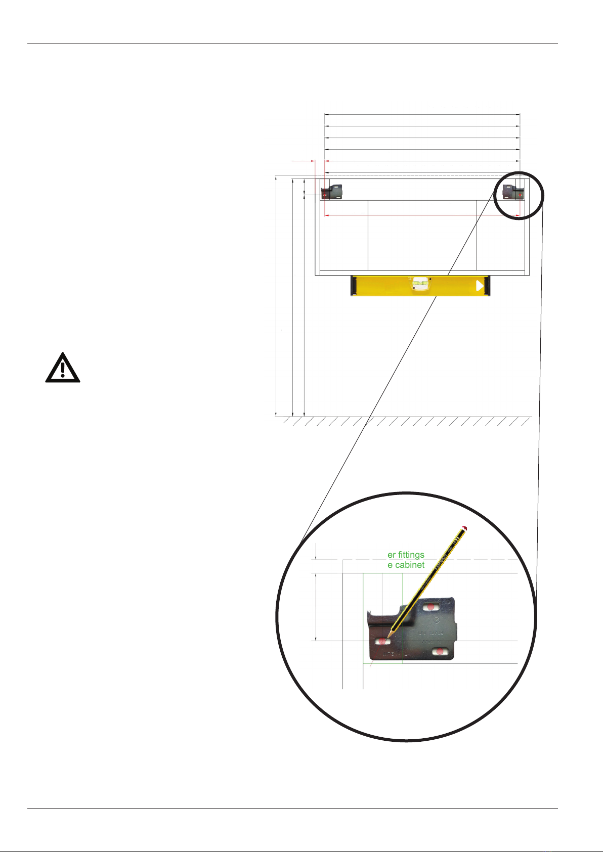
Place the metal plates in line with the wall
(with the help of a spirit level or similar)
and fix them on the wall; follow the drawing
to determine the height and the center-to_center
distance between the plates, mark with a pencil
the position on the plate’s holes.
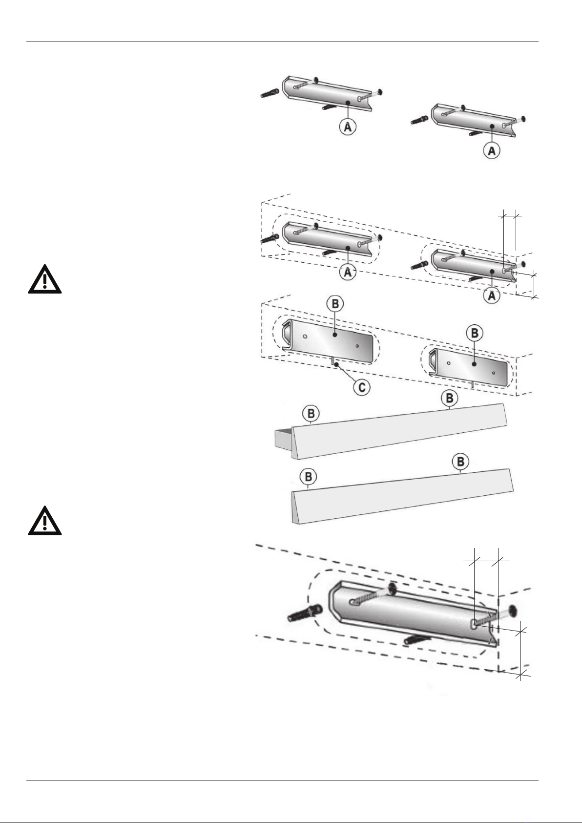
Drill the holes on the wall
To fix the plates, apply the dowels and the screws
in all the holes.
The dowels and the screws supplied by Karol
can be used or not at the installer’s descretion
( this depends on the type of wall where the cabinet
should be mounted).
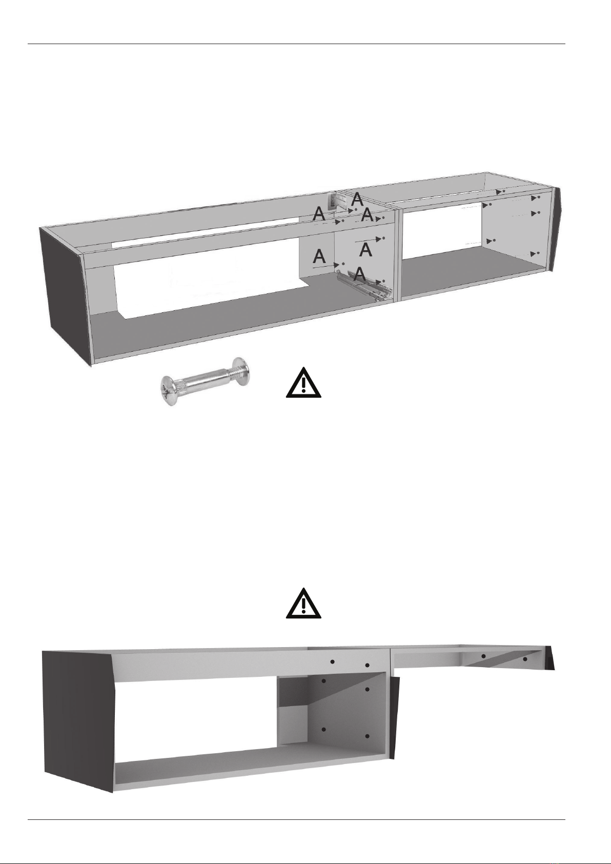
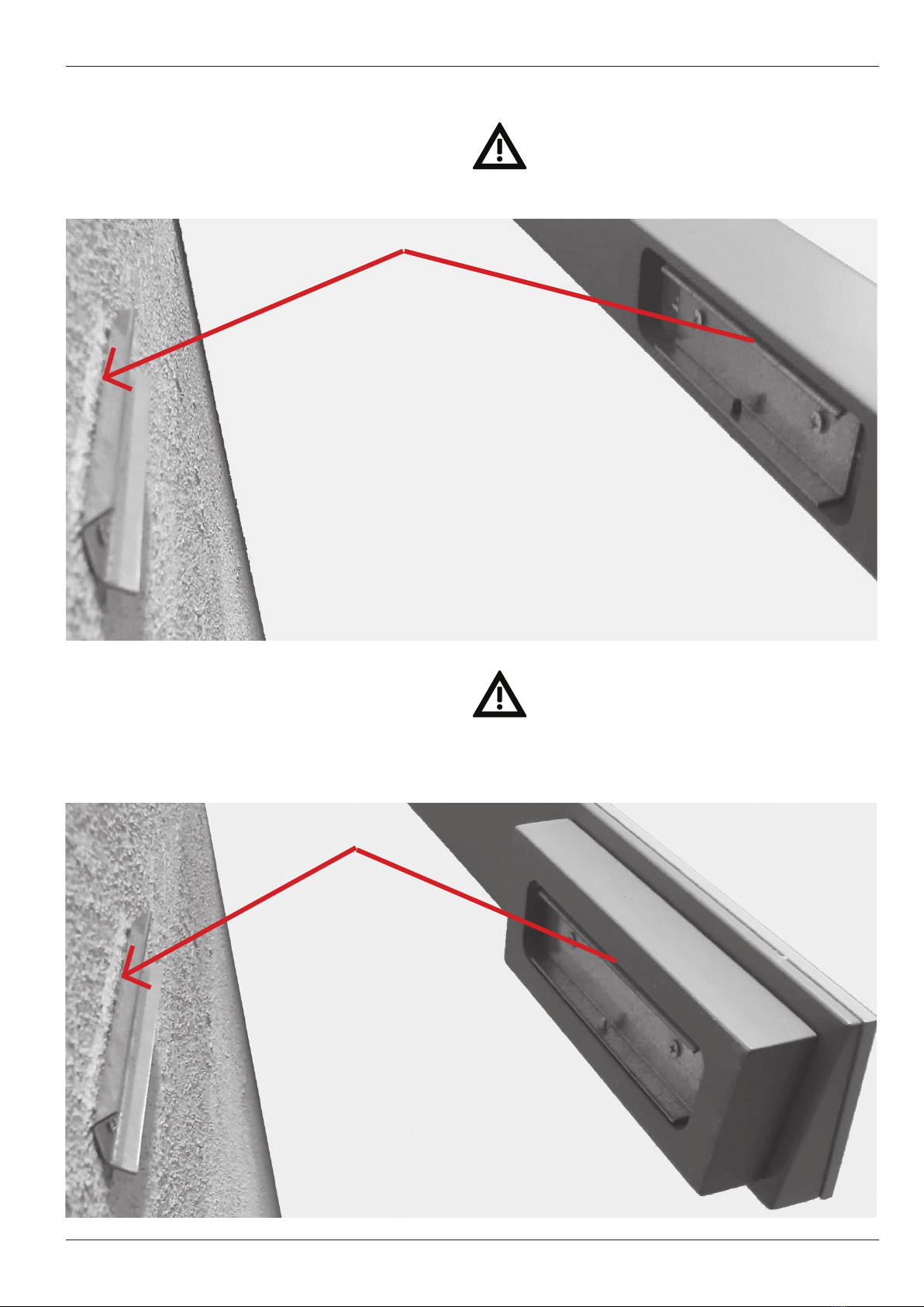
CABINETS INSTALLATION
Image 1
Detail of the wall plate and its holes
ATTENTION
Center-to-center distance
between the external holes
of the metal plates on the wall,
This distance changes depending
on the cabinet width, see image on the right.
cabinet 40 cm=33 cm center-to-center distance
cabinet 60 cm=53 cm center-to-center distance
cabinet 80 cm=73 cm center-to-center distance
cabinet 10 cm=93 cm center-to-center distance
cabinet 120cm=113 cm center-to-center distance
cabinet 140 cm=133 cm center-to-center distance
interasse fori esterni delle placche
60
828 mm from the ground to the external plate hole
888 without top
900
35
60 12
cabinet side
on the cabinet
the plate
hole
center-to-center distance
between external holes of the plates