Kathrein K-LAN 2.4 User manual

1 / 8
EXI 02 LAN 205500006
About these instructions
This document is part of the product.
►Do not install and use the device until you have
read and understood this document.
►Always perform the actions described in this docu-
ment in the sequence listed.
►Keep this document for reference throughout the
life of the device. Pass this document on to any
subsequent owners and users.
The current version of this document can be found at
www.kathrein-ds.com.
You can download an English version of this
user manual from our homepage
www.kathrein-ds.com.
Features
• G.hn modem for the Kathrein Ethernet over Coax
System “K-LAN 2.4”
• Using the existing coax terrestrial distribution
system to create a home network. No need to lay
network cables
• Improved data throughput of up to 2 Gbit/s
• 16 modems can be connected concurrently within
the network
• Integral high selectivity diplexer to prevent interfer-
ence between DVB-T and SAT signals
• Integral switch for connection of 2 network devices
• Coax range up to 700 m
• Supports both IPv6 and IPv4
• Not compatible with series EXI 01 modems
Scope of supply
• EXI 02 LAN
• Ecient plug-in power supply unit
• CAT 6 network cables
• Operating instructions
Accessories
EXI 258 high-pass filter for suppression within the G.hn
operating range. The high-pass filter is screwed into
the input for the terrestrial distribution system. By this
means
for instance the following multi-switches and splitters
can be isolated from G.hn, and the emissions by a
terrestrial antenna can be prevented (see “System exam-
ples” on page 4).
Intended use
The EXI 02 LAN modem is designed exclusively for use
with the Kathrein Ethernet over Coax System “K-LAN
2.4”.
Any other use, or failure to comply with these instruc-
tions and the documentation and instructions supplied
with the devices will result in voiding of the warranty
cover.
Installation and safety instructions
►Failure to comply with these instruc-
tions will result in voiding of the
warranty cover.
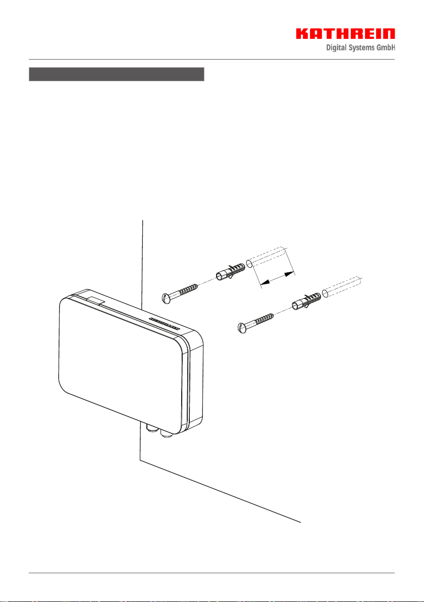
►The equipment may be installed and
operated only in dry indoor areas. Use
the drilling template (see “Dimensions
and drilling template for wall mounting” on
page 5) for wall mounting.
►Make sure that the ventilation slots on
the device are not covered in any way.
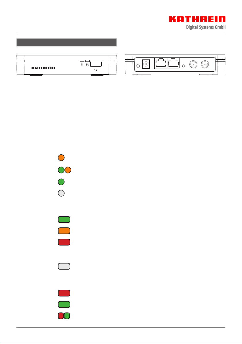
►Connection plugs for coaxial cables: 75
Ohm HF plugs (series F)
►If the port is not used for connection of
a TV set or a similar device, an EMK 03
terminating resistor must be screwed
into the port.
G.hn modem for the
Kathrein Ethernet over Coax System “K-LAN 2.4”

2 / 8
Connections and LEDs
Interpretation of the LED statuses
Power LED (network security)
Continuous
orange
Operation, also “insecure mode” and readiness for “pairing” with other modems
for “secure mode”
Flashing
orange/green Pairing procedure with other modems for “secure mode”
Continuous green Operation and “secure mode” with other modems in the same network
O No operating voltage present
G.hn link LED (coax connection of the modem)
Flashing green Eective data rate is > 300 Mbps
Flashing orange Eective data rate is ≤ 300 Mbps
Flashing red Eective data rate is ≤ 100 Mbps
Continuous
red/green/orange
Eective data rate is the same as for the flashing LED, but no data trac over
the coax connection
O No link available over the coax. Either the attenuation or distance is too great or
the modem is solitary in its logical network
Ethernet LED
Continuous red Ethernet port 1 connected
Continuous green Ethernet port 2 connected
Flashing red/green Data trac over the respective port
Pair Power GigE-1 GigE-2 Reset TV Coax-Link
Ethernet LED
G.hn link LED
Power LED
Pairing button
Power socket
Network port 1
Network port 2
Reset button
TV port
Antenna outlet

3 / 8
Commissioning
1. Plug the power supply unit supplied into the power socket and into the mains socket (the power LED will light up
orange).
2. Connect the modem to the antenna socket using a coaxial cable (with F plugs).
3. Using the Ethernet cable supplied, connect the network device such as a router, TV, PC etc.
4. Further modems can be connected as described in steps 1 to 3.
Pairing
A secure G.hn network connection can be created by pressing the pairing button on the modem and proceeding as
follows:
1. Check that power LEDs of the modems are lit up continuously orange (ex factory status or after a reset: “insecure
mode”).
2. Depress the pairing button on the first modem for about 3 seconds. The power LED will start to flash orange/
green.
3. Depress the pairing button on the next modem for about 3 seconds. The power LED will start to flash orange/
green.
4. On completion of the procedure, the power LED of the second modem will light up continuously green. The
power LED of the first modem will continue to flash orange/green for about 2 minutes, to allow you to add further
modems to the network.
5. To add further modems to the network, repeat step 3.
6. Once all modems are attached to the network, all the power LEDs will light up continuously green. The network
connection is now in “secure mode”.
Removing a modem
To remove a modem from the secure network, or to perform a reset, proceed as follows:
1. Using a pointed object, depress the reset button for about 15 seconds. All the LEDs will go dark briefly.
2. After a short time the power LED will light up continuously orange. The modem is now once again in “insecure
mode” and by pressing the pairing button can be attached to a secure network.
Installation example
ESD 30
Sat
TV
Radio
PC/Laptop
Coaxial cable DVB-S2
Ethernet cable
Coaxial cable DVB-T2
EXI 02 LAN

4 / 8
System examples
KAZ 11/12
UAS
584
(585)
KAZ12
21810002
A
KAZ11
507205
A
EXI 258 | EXR 2508
ESD 30
ESD 30
TV-Gerät
Streaming-Box
ESD 30
WiFi repeater
VDSL
Router
ESD 30
DAB+ 100 highline
SAT
TV-Gerät
SAT / DVB-T2
ESD 30
ESD 30
2
T
err.
V
high
H
high
V
low
H
low
1
4
3
6
5
8
7
18V
Power
OFF
Saving
ON
TV-Gerät
SAT
SAT-Receiver
PC/Laptop
EXI 02 LAN
NAS-System
Coaxial cable
Ethernet cable
EXI 02 LAN
EXI 02 LAN
EXI 02 LAN
A
KAZ 11/12
UAS
584
KAZ12
21810002
A
KAZ11
507205
A
2
T
err.
V
high
H
high
V
low
H
low
1
4
3
6
5
8
7
Power
Saving
20510096
ESD../ESC../EXI..
ESD../ESC../EXI..
EXI 258 |EXR 2558
EXI 258 | EXR 2508
2
T
err.
V
high
H
high
V
low
H
low
1
4
3
6
5
8
7
18V
Power
OFF
Saving
ON
B
EXI 02 LAN
EXI 02 LAN
EXI 02 LAN
EXI 02 LAN

5 / 8
Dimensions and drilling template for wall mounting
80
130
80
=
=
ø5
ø10
DE - 83022 Rosenheim
Sticker
Diagram showing the rear of the EXI 02 LAN. Here you will find the adhesive label with the identifications.

6 / 8
Installation instructions
To mount the EXI 02 LAN on the wall you will need fastenings such as 2 round head wood screws (size
4 x 16 mm) and suitable wall plugs. Make sure that the diameter of the screw heads doe not exceed 9 mm (see
“Dimensions and drilling template for wall mounting” on page 5).
The fastening materials are not included in the scope of supply.
Select screws and wall plugs suitable for the wall to which the modem is to be fastened, so as to achieve optimum
security of attachment.
To attach the modem, proceed as follows:
1. Drill holes to suit the sizes of the wall plugs
2. Insert the wall plugs flush into the drilled holes
3. Screw the screws into the wall plugs until their heads are projecting approx. 3 mm, so that the modem can be
located over them
4. Place the modem on the screws and push it downwards so that it is located in position

7 / 8
Technical data
Type | Order no. EXI 02 LAN | 205500006
Frequency range IP + TV MHz 2 – 1218
Frequency range IP MHz 2 – 200
Frequency range TV MHz 258 – 1218
Through loss, TV dB 2
Modem current consumption mA 250
Phy rate Gbit/s 2
Data rate TCP (gross) max. Mbit/s 900
Ports F connectors, RJ45, DC socket 5.5 x 2.5 mm
Standards supported G.hn G.9960 1-4
Permissible ambient temperature °C 0 to +40
Dimensions (W x L x H) mm 92 x 130 x 29
Weight kg 0.125
Power supply unit
Nominal input voltage V 230
Voltage secondary V 12
Output current max. A 1
Nominal input power (250 mA load) W 3
Information about the coaxial distribution system
In principle, any coaxial distribution system in the house can be used. The requirement is that a frequency range
of 200 MHz is available and is not being used for other purposes, because otherwise interference can occur. G.hn
is robust can be expected to achieve a connection even under very adverse conditions. Do not use the modems in
cable network environments in which the same frequency range is used. Only appropriately trained personnel may
undertake a secure installation.
Electronic equipment
Electronic equipment must not be disposed of in domestic waste. According to directive 2012/19/EU OF
THE EUROPEAN PARLIAMENT AND COUNCIL of 4 July 2012 on waste electrical and electronic equipment,
it must be disposed of professionally. At the end of its service life, take this unit to a designated public
collection point for disposal.
Disposal

KATHREIN Digital Systems GmbH | Anton-Kathrein-Str. 1–3 | 83022 Rosenheim | Germany | Phone +49 731 270 909 70
For your notes
Table of contents
Other Kathrein Modem manuals

Kathrein
Kathrein DCG 10 Operation and maintenance manual

Kathrein
Kathrein ESM 20 User manual

Kathrein
Kathrein EXI 01 User manual

Kathrein
Kathrein DCV 10 User manual

Kathrein
Kathrein DCV 10 Operation and maintenance manual

Kathrein
Kathrein 27445 User manual

Kathrein
Kathrein DCM 32 User manual

Kathrein
Kathrein DCM 32 User manual