Katool KT-810 Guide

Tire Changer Model# KT-810
KATOOL
Installation, Operation and Maintenance User’s Manual
ITSK.COM

Tire Changer KT-830 User’s Manual
1
Semi-automatic swing arm tire changer
Parameters: rim: 12"-24", Tire width:14"-26", tire diameter: 1160mm

Tire Changer KT-830 User’s Manual
2
● FAILURE TO OPERATE THIS EQUIPMENT AS DIRECTED MAY CAUSE INJURY OR
DEATH. PLEASE READ THIS ENTIRE MANUAL PRIOR TO INSTALLATION AND OPERATION.
BY USING THIS PRODUCT, YOU AGREE THAT YOU FULLY UNDERSTAND AND
COMPREHEND THE FULL CONTENTS OF THIS MANUAL. MAKE SURE ALL OPERATORS
READ AND UNDERSTAND.
● Do not operate this machine until you read and understand all the dangers, warnings and cautions
in this manual.
⚫Follow all installation instructions.
⚫Carefully check the unit for correct initial function.
⚫Read and follow the safety instructions. Keep them readily available for machine operators.
⚫Make certain all operators are properly trained, know how to safely and correctly operate the
unit, and are properly supervised.
⚫Allow unit operation only with all parts in place and operating safely.
⚫Carefully inspect the unit on a regular basis and perform all maintenance as required.
⚫Service and maintain the unit only with authorized or approved replacement parts.
⚫Keep all instructions permanently with the unit and all decals on the unit clean and visible.

Tire Changer KT-830 User’s Manual
3
IMPORTANT SAFETY INSTRUCTIONS
READ BEFORE OPERATING UNIT
•Keep the machine away from moist, corrosive and hot surrounding.
•Protective goggles, safety glasses, or a face shield must be worn by the operator. Care should be
taken to see that all eye and face safety precautions are followed by the operator. ALWAYS WEAR
SAFETY GLASSES.
•Keep guards and safety features in place and in working order.
•Wear proper protective clothing. Safety toe, non-slip footwear and protective hair covering to
contain hair is recommended. Do not wear loose clothing, or jewelry when operating the machine.
•If an extension cord is necessary, a cord with a current rating equal to or greater than that of the
equipment should be used. Cords rated for less current than the equipment may overheat. Care
should be taken to arrange the cord so that it will not be tripped over or pulled.
•Read and understand this manual before operating.
•Do not operate damaged equipment or if the power cord is cut or worn.
•Keep work area clean and well lighted. Cluttered and/ or dark areas invite accidents.
•Avoid dangerous environments. Do not use power tools or electrical equipment in damp or wet
locations, or expose them to rain and moisture
•Avoid unintentional starting. Be sure the tire changer is turned off before servicing.
•Disconnect the tire changer before servicing.
•Use only manufacturer’s recommended accessories. Improper accessories may result in personal
injury or property damage.
•Repair or replace any part that is damaged or worn and that may cause unsafe operation.
•Do not operate damaged equipment until it has been examined by a qualified service technician.
•Never overload or stand on the tire changer.
•Do not allow untrained persons to operate machinery.
•To reduce the risk of fire, do not operate equipment in the vicinity of open containers or flammable
liquids.
•Adequate ventilation should be provided when working on operating internal combustion engines.
•Keep hair, loose clothing, fingers, and all parts of body away from moving parts.
•Use equipment only as described in this manual.
•Use only manufacturer’s recommended attachments.

Tire Changer KT-830 User’s Manual
4
TABLE OF CONTENTS
Overview ........................................................................................................................................................................6
1.1 Important note ...................................................................................................................................................6
1.2 Qualified users...................................................................................................................................................6
1.3 Notes.................................................................................................................................................................6
1.4 Danger warning signs ........................................................................................................................................8
1.5 Noise standard...................................................................................................................................................8
Equipment description ....................................................................................................................................................9
2.1 Product introduction ..........................................................................................................................................9
2.2 Technical parameters .........................................................................................................................................9
2.3 Transportation ...................................................................................................................................................9
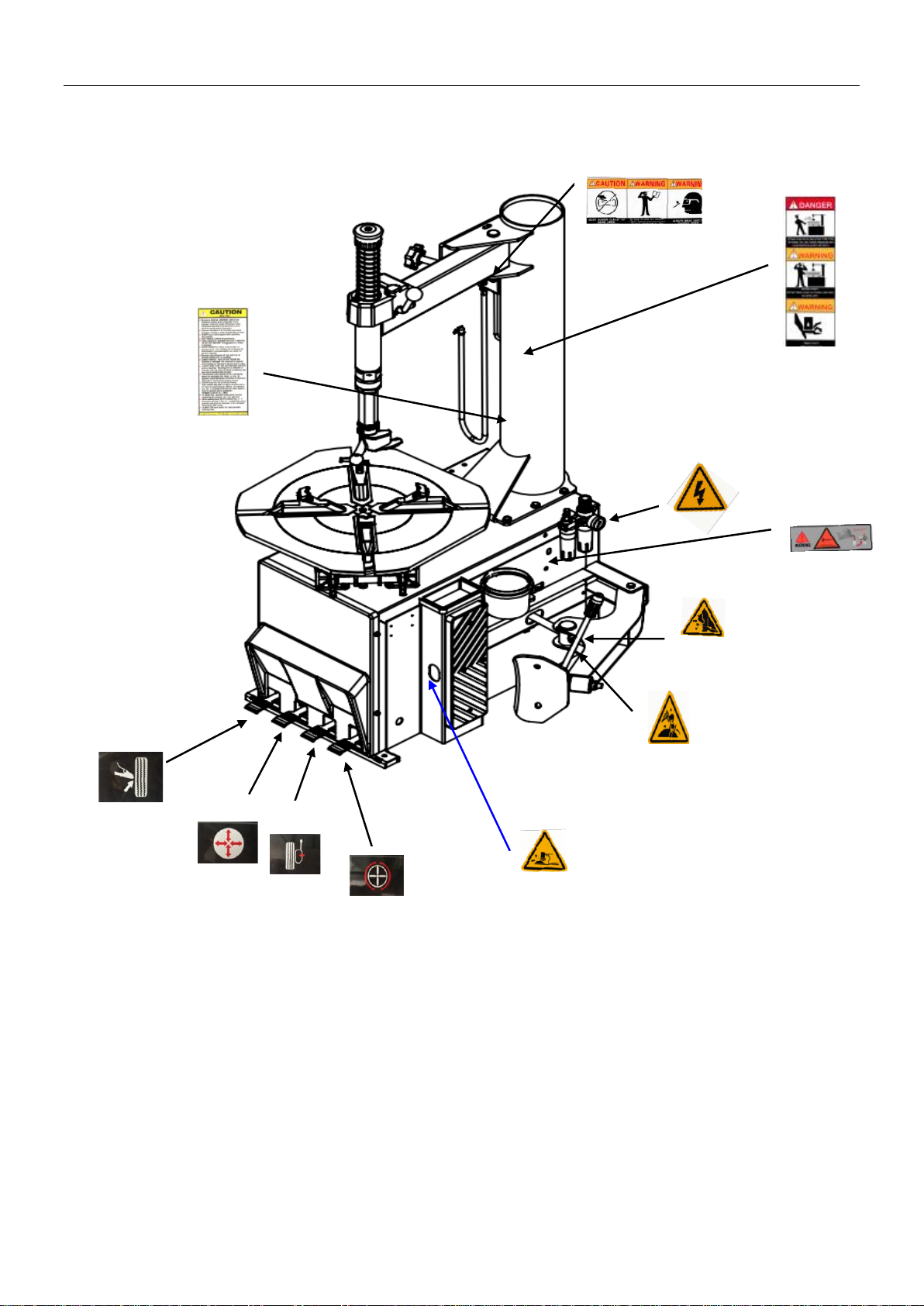
2.4 Figure and part name ....................................................................................................................................10
Installation and commissioning instructions ..................................................................................................................13
3.1 Installation Preparation ....................................................................................................................................13
3.2 Precautions during installation .........................................................................................................................14
3.3 Main installation procedure..............................................................................................................................15
3.4 Check the project table after installation...........................................................................................................16
3.5 Commissioning and debugging........................................................................................................................16
Operation......................................................................................................................................................................17
4.1 Operating notes ...............................................................................................................................................17
4.2 Disassembly operation process ........................................................................................................................17

Tire Changer KT-830 User’s Manual
5
4.3 Mounting……………………………………………………………………………………………………………………………………………………….23
Maintenance ..................................................................................................................................................................34
5.1 Maintenance....................................................................................................................................................34
5.2 Storage and scrap.............................................................................................................................................37
Fault causes and Solutions ............................................................................................................................................37
Parts List and Exploded Drawings ...................................................................................................................................39
Warranty……………………………………………………………………………………………………………………………………………………………………….41

Tire Changer KT-830 User’s Manual
6
Overview
1.1 Important note
1.1.1 Thank you for your purchase and use of this product. Please read and follow the safety
instructions. Keep them readily available for machine operators.
1.1.2 Service and maintain the unit only with authorized or approved replacement parts.
1.2 Qualified users
1.2.1 Make certain all operators are properly trained, know how to safely and correctly
operate the unit, and are properly supervised.
1.2.2 Electrical appliances must be operated by the normal electrician.
1.2.3 Do not attempt to operate this equipment if you have never been trained on basic tire
service and mounting / dismounting procedures.
1.3 Notes
1.3.1 Before using the product, please carefully read every part of the manual, especially the
operation of the safety and mechanical maintenance of the part.
1.3.2 Use the tire assembly machine must be operated by professional training personnel.
1.3.3 Tire disassemble is forbidden to use in explosive gas.
1.3.4 Before the machine is connected, the user must ensure that the use of power and gas
supply and mechanical requirements, the circuit system must be operated by professional
staff.
1.3.5 In the operation process, do not face close to the turntable, so as to avoid dust and
other debris hit the operator's eyes. In order to ensure safety, mechanical operation, to be
careful, do not touch the inflatable pedal, so as to avoid accidents.
1.3.6 To operate tire inflation must be very careful, strictly according to the instructions for
operation, if the tire suddenly burst, tire assembly machine design and structure is not to
protect the operator's personal safety (or any mechanical in the vicinity of the kind).
1.3.7 Operation of the tire changer, necklace, loose clothing, etc., may give the operator to
bring personal injury.
1.3.8 In the process of removing or installing the operation of the tire, the turntable has
always been to ensure that the clockwise rotation; if there is a counter clockwise rotation
indicates that the turntable is a failure or operator error.

Tire Changer KT-830 User’s Manual
7
1.3.9 Manufacturers are responsible for the damage caused by the use of other parts of the
manufacturer or the damage of the safety device.
1.3.10 periodically check the oil mist, oil, if the oil level is low and need to unscrew the oil
cup and then add. Oil mist using models for ISO Hg and viscosity for ISO vg32 oil mist
special oil (such as: Esso Fedis k32, 1405, Mobil Vacouline, KLUBER32)
1.3.11 if the product is not used for a long time, please user A. disconnect all power supply,
B. and lubricate the turntable fixture slide to prevent oxidation.
1.3.12 when deciding to scrap equipment, to determine the total energy of all the energy to
be cut off, according to the relevant laws and regulations for all non-ferrous metals and non-
ferrous metal scrap processing.
Tire Changer KT-830 User’s Manual
8
1.4 Warning signs
1.5 Noise standard
The noise of the tire changer shall be less than 70dB. for your health, and it is recommended
that you place a noise meter in your operating area.

Tire Changer KT-830 User’s Manual
9
Equipment description
2.1 Product introduction
This model of semi-automatic tire changer is a convenient and quick disassemble and
installation of wheel size of 10” to 28”, the tire width of 110-380mm and the diameter of the
tire is 1040mm.
2.2 Technical parameters
Special points
Technical parameters
Outer rim
10"-22"
Inner rim
12"-24"
Maximum tire diameter
1040mm(41")
Maximum tire width
380mm(15")
Pressing force (10bar)
5510 lbs. (2500kg)
Operating air pressure
8bar-10bar(116-145psi)
Maximum charge pressure
3.5bar(50psi)
Power supply voltage
120V 1ph/220V 3ph
Motor power
1.1kw/0.75kw / 1.5kw
Outline dimension
1120×750×860
Net weight
485 lbs. (220kg)
Working state noise
<70dB(A)
2.3 Transportation
Handling of the machine must be performed only with an appropriate lifting device such as a forklift
or pallet jack. Only personnel who are experienced and qualified on material handling procedures
should handle any transportation or moving of machine.
This manual suits for next models
1
Table of contents
Popular Tyre Changer manuals by other brands


Coats
Coats 80C operating instructions

HENNESSY INDUSTRIES
HENNESSY INDUSTRIES Coats Rim Clamp X-Model Series instructions

Draper
Draper 78612 user manual

Aston Global
Aston Global ATC-5800 Installation, Operation and Maintenance User’s Manual

HENNESSY INDUSTRIES
HENNESSY INDUSTRIES Coats CHD-4730-4730W Operating and maintenance instructions

Butler
Butler NAV11N instruction manual