GATmatic TWC-1600 User manual

TIRE CHANGER FOR TRUCK TWC-1600
AUTOMATIC TIRE CHANGER
INSTRUCTION MANULA
TIRE CHANGER
ITEM NO: TWC-1600

TIRE CHANGER FOR TRUCK TWC-1600
1
1 GENERAL INFORMATION
Tire changer has been specifically designed to demount high-speed bus and
truck tires with rims form 14"to 26"and a maximum 1600mm diameter
Any other use is improper and therefore not authorized before beginning any
kind of work on or with this machine, carefully read and understand the
contents of these operating instructions.
Shall not liable for any injury to persons or damage to things caused by
improper use of this machine.
Keep this manual near the machine and consult it as needed during
operations.
2 TECHNICAL DATA
Pump motor
1.5KW
Gear-box motor
1.8KW
Handles rim form
14"-26"
Max. wheel diameter
1.600mm
Max. wheel width
780mm
Weight(with standard accessories)
518kg
Acoustic pressure level(at work)
LPA<70dB(A)
3 GENERAL SAFETY REGULATION
The use of this machine is reserved to specially trained and authorized
personnel.
Any unauthorized changes or modifications to the machine, in particular to its
electrics system, relieve form all liability.
Removing or tampering with the safety devices installed on this machine is in
violation of European safety Regulations.
4 SAFETY DEVICES
Tire changer has a number of safety devices designed to guarantee the utmost
operator safety:
1. Check valve on the spindle opening hydraulic line (inside the swivel
connector, see fig. B/1).This prevents the wheel form falling form the spindle
if the hydraulic is accidentally broken.
2. pilot operated dual seal check valve(see Fig. B/2)
This prevents the spindle carrier arm from dropping if the hydraulic circuit
accidentally breaks.
3. Pressure relief valve factory set at 130 bar ±5%(see Fig. B/3).
Any work, however minor, on the electric system must
be done exclusively by professionally qualified
personnel.

TIRE CHANGER FOR TRUCK TWC-1600
2
This limits the pressure in the hydraulic circuit and ensure correct operation
of the plant.
4. Pump motor overload cut-out (inside the electric enclosure).
This cuts in if the motor overheats to prevent it from burning out.
5. Mechanical tool arm tip lock device (see Fig. B/4).
Prevents the arm form being moved to its “non-working position” if the tool
has been removed.
CAUTION!
Removing or tampering with safeties is in violation of European Safety
Regulations and relieves manufacturer of any and all liability for injury to
persons to damage to things caused or referable to such acts.
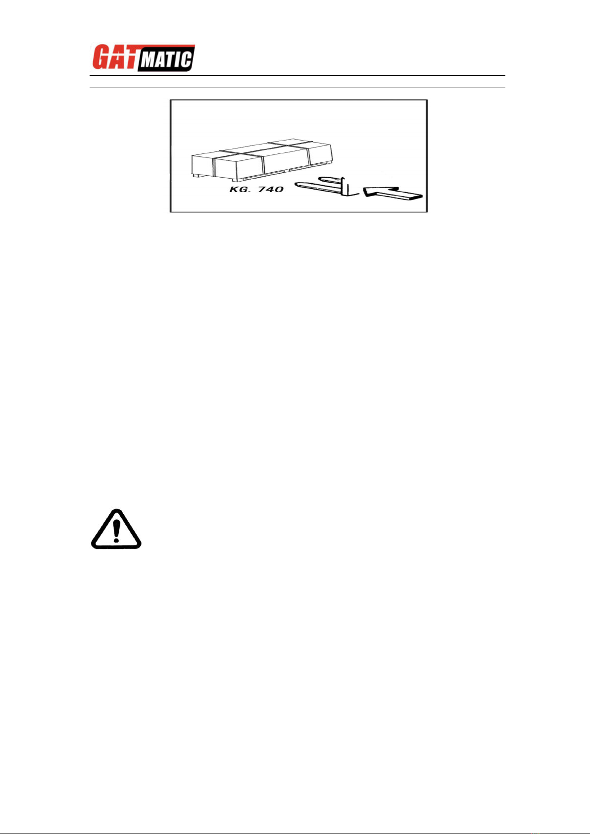
5 TRANSPORT
Depending on customer request, the machine is delivered in 3 packing
versions:
1-in a wooden crate with pallet
2-fixed to a pallet
3-no packing
In all cases the machine is protected by a plastic covering.
In the first and second case, the machine must be handled with a fork-lift truck
with the forks positioned as shown in the figure.
TIRE CHANGER FOR TRUCK TWC-1600
3
6 UNPACKING
Once the packing material has been removed, check the machine visually for
any signs of damage.
Keep the packing materials out of the reach of children as they can be a source
of danger.
N.B.: Keep the packing for possible future transport.
7 INSTALLATION PLACE
Choose the place the machine is to be installed in compliance with current work
place safety regulations.
The floor should not be broken or uneven so that the machine will be stable and
the platform rollers can move freely.
If the installation is outdoor, it must be protected by some kind of roofing
against rain.
The following work environment conditions are applicable: Relative
humidity :form 30-95% without condensation; Temperature: form 0-55℃.
WORKPLACE REQUIREMENTS
Maximum machine space requirements are 1950×1600mm with a minimum
distance from walls as shown in the diagram.
Caution! These measurements are also the tire changers working range.
Persons other than specially trained and authorized operators are
expressly forbidden to enter this area.
Position the tire changer lifting it with the specific bracket (1, fig. A) with the tool
carrier arm (2, Fig. A) lowered all the way. The spindle (3, Fig. A) closed and
the tool carrier slide (4, Fig. A) at its stop close to the arm.
ATTENTION!
The machine must not be operated in explosive atmospheres.

TIRE CHANGER FOR TRUCK TWC-1600
4
It is not essential to anchor the machine to the floor however, the floor must be
smooth and permit the platform rollers to move freely.
ELECTRIC HOOK UP
Before making any electric hook up, check to be certain that the mains
voltage corresponds to that stamped on the voltage tag (attached to the
cord near the tire changer’s plug).
It is absolutely essential that:
-the system is equipped with a good grounding circuit.
-The machine is connected to a power supply line circuit breaker set for
30 mA.
-The current in-stake is adequately protected against over-currents with
fuses or automatic magneto-thermic switch with rated values as shown in
the table.
Note the required power draw as high-lighted on the data plate fixed to
the tire changer. Check to make sure the shop electric wiring circuit is
dimensioned sufficiently to carry this.
Manufacturer shall not be liable for any injury to persons or damage to
things caused by failure to comply with these regulations and can cancel
warranty coverage.
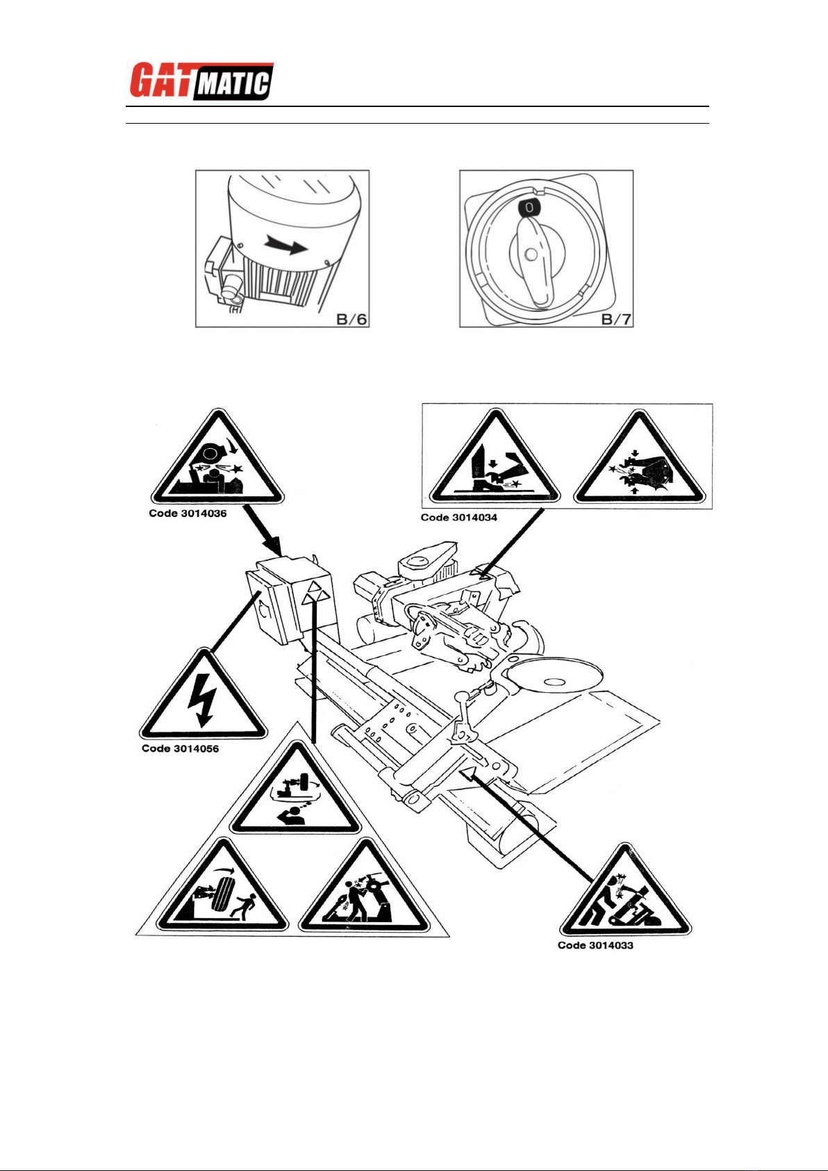
SENSE OF ROTATION CHECKS
power supply
Rated current
Fuse
Switch
220v-3ph-50/60Hz.
10A
16A
Work on the electric system, even if minor, must be done
exclusively by professionally qualified personnel.
TIRE CHANGER FOR TRUCK TWC-1600
5
Connect the machine to the mains, switch “ON”(5,fig.B/7)and check that the
gearbox motor rotation corresponds to the indicating arrow(6,fig.B/6).
8 IDENTIFYING WARNING SIGNALS
WARNING!
Unreadable and missing warning labels must be
replaced immediately.
Don’t interpose any object witch could prevent the
operator from seeing the labels.
Use the code in this table to order labels that you
might need.
TIRE CHANGER FOR TRUCK TWC-1600
6
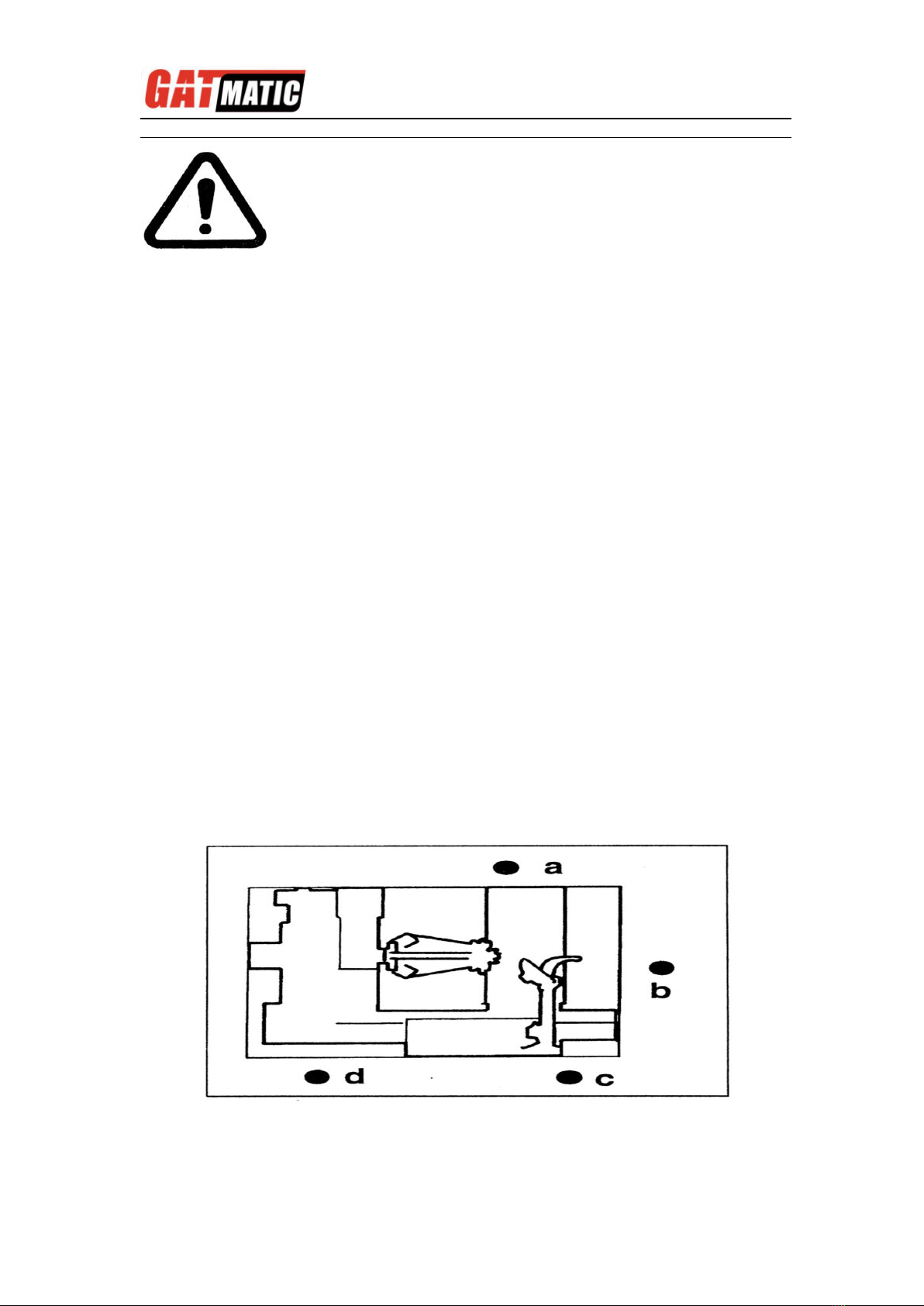
9 IDENTIFICATION OF CONTROL
The mobile control center (fig. c) enables the operator to work at any position
around the machine .on this mobile control center the following controls are
located:
-The lever (8, fig. c) which in position a lifts the chuck arm and in position b
lowers it; in position cmoves the tool holder arm and in position dmoves them
away. (Note: in order to memorize this operation, there is a hole in the lever
guard corresponding to position c).
-The chuck switch (9, fig. c) when moved upwards, opens the arms of the
self-centering chuck (LOCKING), and when moved down, close the arm of the
self-centering chuck (UN-LOCKING).
-The pedal (10, fig. c) when pressed on the left or right side rotates the
self-centering chuck in the same direction as shown by the arrows placed on
the foot pedal.
NOTE: all the controls are very sensitive and small movements of the .machine
can be done with precision.
The GATMATIC TWC-1600 tire changer also has:
Lever (15, Fig. D) to tip the tool carrier arm (14, Fig. 4) form its work to its
non-working position and vice-versa.
Handle (19, Fig. D) that permits alternative use of the bead-breaking disk
(17,Fig.D)or the hooked tool(18,Fig.D).
10 WORKING POSITION
The diagram shown here illustrates the various working positions
(A, B, C, D) referred to in the following pages describing how to use the tire
changer.
Use of these positions ensures greater precision, speed and safety for those

TIRE CHANGER FOR TRUCK TWC-1600
7
using the machine.
11 CORRECT OPERATION CHECKS
Before using the tire changer, a number of checks should be made to ensure it
works correctly.
CAUTION! The operations described here should be done with the tool carrier
arm in its non-working position.
First use lever (15, Fig. d) to tip the arm to this position.
1) Move the joystick (8, Fig. c) up (a): the spindle carrier arm (2, Fig. a) should
lift; move the joystick down (b): the arm should lower. Move the joystick
towards the left (C): the tool carriage and the mobile platform (13, Fig. D)
Should move towards the spindle (3, Fig. A);move the joystick towards the
right (d) the carriage and platform should move away from the spindle.
2) Tum switch lever (9, Fig. C) towards the top: the spindle arm should
open; move the lever down and the spindle arms should close.
3) Depress the right pedal (10, 568 Fig. C): the spindle (2, Fig. A) should turn
clockwise; depress the left pedal: the spindle should turn anticlockwise.
4) Check to be certain the hydraulic circuit is working correctly:
-move switch lever (9, Fig .c) towards the top until the spindle arms are fully
extended.
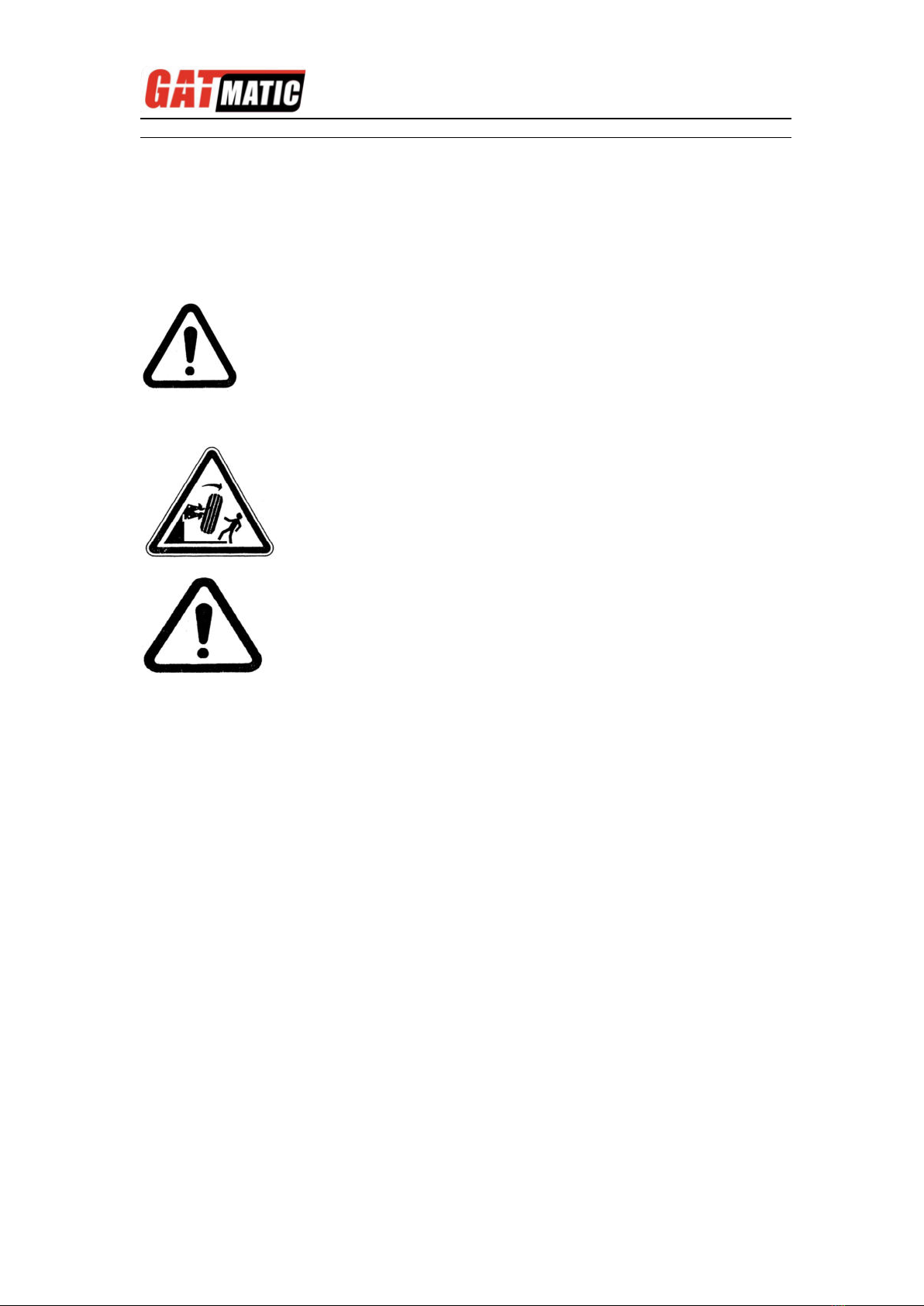
CAUTION!
Do not move your face close to the tool carrier arm when you
release it to tip it as needed.
DANGER!
When the spindle carrier arm is lowered. There is
always a potential for crushing anything in its
movement range. Always work from the position given
in the instructions keep well out of the working range
of the various moving arms.
(2, Fig. A)
DANGER!
When the spindle arms open or closed, there is always a
potential for crushing anything in their movement
range.
Always work form the position given in the instructions
keep well out of the spindle’s working range.
Lifting arm lift or lower and hydraulic chuck open or close, there is
always a potential for crushing anything in its movement range.
Always work form the position given in the instructions keep well
out of the working range
TIRE CHANGER FOR TRUCK TWC-1600
8
-hold the switch lever in this position (Top) and check if the pressure shown on
the gauge on the swivel fitting is 130 bar 5%.
If the pressure shown in not as indicated here, do not use the tire changer
and call our GATMATIC assistance team.
12 USE
LOCKING THE WHEEL
Always remember that the safest locking is on the central flange.
WARNING!
In locking the wheel, make sure that clamps are properly
positioned on the rim, so as to prevent the tire form falling
WARNING!
During all operations, keep hands and the other parts of the body as possible
form moving parts of the machine.
Necklaces, bracelets and too large clothes can be dangerous for the operator.
1) Take the mobile control unit to work position B.
2) Pull the tool-holder arm (14, Fig. D) into the upright
position.
3) Operating form the mobile control center, move the sliding table (13,
fig. D) away form the self-centering chuck and place the wheel in vertical
position on the sliding table.
4) Continuing to operate form the mobile control center, lift or lower the
arm in order center the self-centering chuck (3, fig. a) relative to the
rim.
5) With the jaws (22, fig. A) in the closed position, move the wheel on
the sliding table to the self-centering chuck. Operate the chuck switch
(9, fig. C) to open the self-centering chuck and lock onto the inside wheel
rim. The most convenient locking position on the rim may be selected
according to figE/1-E/2-E/3-E/4-E/5 and E/6.

TIRE CHANGER FOR TRUCK TWC-1600
9
N.B. for rims with channel, clamp the wheel so that the channel is near the
outside of the rim (fig. E/1)
TUBELESS AND SUPERSINGLE WHEELSBEAD
BREAKING
1) Look the wheel on the self-centering chuck, as previously described, and
ensure that the tire is deflated.
2) Take the mobile control unit to work position C.
3) LOWER THE TOOL-HOLDER ARM (14, Fig. F) into is working position and
allow it to lock.
4) Operating form the mobile center, manoeuvre the wheel until the outside of
the rim skims the bead-breaker disk (fig. F).
5) Rotate the wheel and at the same time, advance the bead-breaker plate
with small forward movements following the profile of the rim, with the plate.
6) Continue until the first bead is fully detached. To facilitate this operation,
lubricate the bead and the edge of rim with tire lubricant whilst the wheel is
rotated.
DANGER!
This operation can be extremely dangerous.
Do it manually only if you are certain you can keep the wheel
balanced.
For large and heavy tires an adequate lifting device must be used.
DANGER!
Do not very the area with a wheel clamped on the tyre changer
and lifted up from the floor.

TIRE CHANGER FOR TRUCK TWC-1600
10
Remember that the stronger the tire’s adherence to the rim. The slower must be
the disk’s penetration.
7) Bring the tool carrier arm (14, Fig. F) back form the edge of the rim. Release
the hook, raise the arm to its non-working position, shift it and rehook it in its
second work position (Fig. G).
8) Push the double headed tool lever (19, Fig. G) and turn the head 180º until it
locks automatically.
Then slide the tool-holder arm along the sliding table and lock it in position.
Repeat the operation previously described until the second bead is completely
broken.
DANGER!
Always check to be certain that the arm is corrected hooked to
the carriage.
DANGER!
The bead breaker disk must NOT be pressed against the rim but
against the bead.
CAUTION!
To avoid all risk, lubricate the beads turning the wheel
CLOCKWISE if you are working on the outside plane and
ANTICLOCKWISE if working on the inside plane.
DANGER!
Do not hold your hands on the tool when you bring it back
to its work position. Your hand(s) could be trapped between
the tool and the wheel.
9) Take the mobile control unit to work position D.

TIRE CHANGER FOR TRUCK TWC-1600
11
N.B.: During the bead breaking. The claw (18, Fig. G) can be lowed so that it is
out of the way.
DEMOUNTING
Tubeless tires can be demounted in two ways:
1) If the tire is not difficult to demount, once the beads have been loosened, use
the bead disk to push against the inside plane of the tire until both beads come
off the rim (see Fig. H)
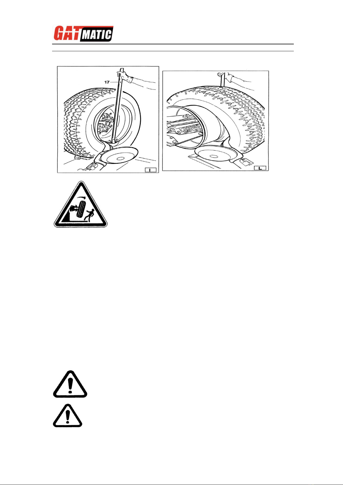
2) With supersingle or very hard tires the procedure described above cannot be
used. The hook tool will have to be used as follows:
-Transfer the tool carrier arm to the outside plane of the tire.
-Rotate the wheel and at the same time move the hook tool forward inserting it
between rim and bead until it is anchored to the bead (see Fig. I)
-Move the rim 4-5 cm form the tool taking care that it does not unhook form the
bead.
-Move the hook tool towards the outside until the red reference dot is by the
outside edge of the rim.
-Insert lever BL (17, Fig. I) between rim and bead at the right of the tool.
-Press down on the lever and lower the wheel to bring the edge of the rim about
5 cm form the hooked tool.
-Turn the wheel anticlockwise pressing down on lever BL until the tool bead is
completely off.
-Move the tool carrier arm to its non-working position and then move it to the
inside plane of the wheel.
-Turn the hook tool 180º and insert it between rim and bead (see Fig. L). Move
it until the bead is by the edge of the rim (best to do this with the wheel turning).
-Move the rim about 4-5 cm from the tool making sure the hook does not detach
form the rim.
-Move the hook tool so that its red reference dot is about 3 cm inside the rim.
-Insert lever BL (17,Fig.I) between rim and bead at the right of the tool.
-Press down on the lever and lower the wheel to bring the edge of the rim about
5 cm form the hooked tool. Turn the wheel anticlockwise pressing down on
Take the mobile control unit to work position C.
Take the mobile control unit to work position B.
Take the mobile control unit to work position D.
Take the mobile control unit to work position B.
TIRE CHANGER FOR TRUCK TWC-1600
12
lever LA until the tire comes completely off the rim.
MOUNTING
Tubeless tires can be mounted using either the bead breaker disk or the hook
tool. If the tire is not problematic, use the bead loosener disk. If the tire is very
rigid, the hook tool must be used.
TIRE MOUNTING WITH THE DISK
Follow these steps:
1) If the rim has been removed form the spindle, put it back on the spindle as
described in the section on “CLAMPING THE WHEEL”
2) Lubricate both beads and the rim with tire manufacturer recommended
lubricant.
3) Attach the RP clip to the outside edge of the rim at the highest point (see
Fig.M).
4) Put the tire on the platform and lower the spindle (make sure the clip is at
the high point).
DANGER!
When the beads come off the rim, the tire will fall.
Check to make sure there are no bystanders in
the work area.
CAUTION!
Make sure the clip is firmly attached to the rim.
Take the mobile control unit to work position B.

TIRE CHANGER FOR TRUCK TWC-1600
13
5) Lift the rim with the tire hook to it and turn it anticlockwise about 15-20 cm.
The tire will be positioned tilted across the rim.
6) Position the bead loosener disk against the second bead of the tire and turn
the spindle until the clip is at the low point(at 6 o’clock)
7) Move the disk away form the wheel.
8) Remove the clip and replace it at 6 o’clock outside the second bead (see
Fig.N).
9) Turn the spindle clockwise 90º to bring the clip to 9 o’clock.
10)Move the disk forward until it is about 1-2 cm inside the edge of the rim.
Begin to turn the spindle clockwise checking to make sure that, with a 90º
turn, the second bead begins to slip into the center well.
11)When the bead is fully mounted, move the tool away form the wheel, tip it to
its non-working position and remove the clip.
12)Position the platform under the wheel, lower the spindle until the wheel rests
on the platform.
13)Close the arms of the spindle completely. Support the wheel to prevent it
falling off.
14)Move the platform to remove the wheel form the spindle.
15)Remove the wheel.
NB: If the tire permits it, the operation described above can be speeded
up by mounting both beads at the same time:
Take the mobile control unit to work position C.
Take the mobile control unit to work position B.
DANGER!
This operation can be extremely dangerous. Do it manually only
if you are certain you can keep the wheel balanced.
For large and heavy tire an adequate lifting device must be used.
TIRE CHANGER FOR TRUCK TWC-1600
14
-Follow the steps described under points 1,2,3,4 described above but instead
attaching the clip to just the first bead (refer to point 4)clip it to both.
-Lift the rim with the tire hooked to it and turn it anticlockwise 15-20 cm (clip at
10 o’clock).
-Follow the steps described in points 10,11,12,13,14,15 above.
MOUNTING WITH THE HOOKED TOOL
1) Follow the steps described in points 1,2,3,4,5 for mounting with the disk.
2) Move the tool carrier arm to its non-working position. Move it to the inside
plane of the tire and rehook it at this position.
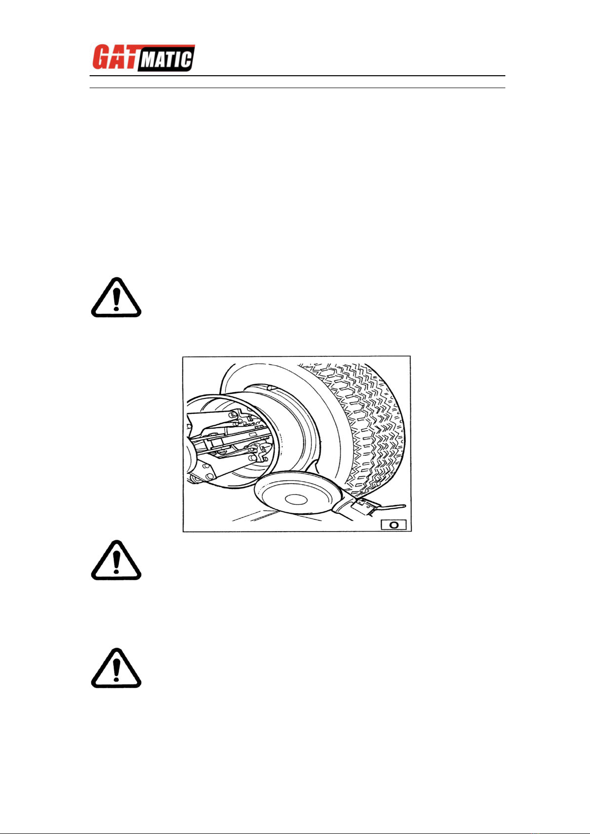
3) Check to make sure the hook tool is positioned on the wheel side. If not,
press lever (19,Fig.D)and turn it 180º.
4) Move the tool forward until the red reference dot is lined up with the outside
edge of the rim and about 5 mm form it(see Fig.O).
5) Move to the outside of the wheel and check the exact position of the took
visually and adjust it as needed. Then turn the spindle clockwise until the
clip is at the bottom (6 o’clock). The first bead will be on the rim.
6) Remove the clip.
7) Remove the tool from the tire.
8) Move the tool carrier arm to its non-working position. Move it to the outside
plane of the tire and rehook it in this position.
9) Turn the tool 180º with lever (19,Fig.D).
Take the mobile control unit to work position D.
Take the mobile control unit to work position C.
Take the mobile control unit to work position D.

TIRE CHANGER FOR TRUCK TWC-1600
15
10) Attach the clip at the bottom (6,o’clock) outside the second bead(see
Fig.N)
11)Turn the spindle clockwise to about 90º (clip at 9 o’clock).
12)Bring the tool forward until the red reference dot is lined up with the outside
edge of the rim and about 5 mm form it. Begin to turn the spindle clockwise
and check if, after about 90º of rotation the second bead has started to slip
into the center well. Continue turning until the clip is at the bottom (6 o’clock).
The second bead will now be mounted on the rim.
13)Follow the steps described in points 11,12,13,14,15 for mounting with the
disk since this will ensure that the wheel is removed correctly form the
machine.
TUBED WHEELS BEAD BREAKING
WARNING: Unscrew the bush which fixes the valve when deflating the tire
so that the valve, coming in the inside of the rim, is not an obstacle during
bead breaking.
Follow all the steps described previously for bead breaking tubeless tires.
With tubed tires, however, stop disk movement as soon as the bead has
loosened to avoid damaging the tube inflation valve.
DEMOUNTING
1) Tip the tool carrier arm (14, Fig. D) to its non-working position. Move it to the
outside plane of the wheel and rehook it in this position.
2) Rotate the wheel and at the same time move the hook tool (18, Fig. D)
forward inserting it between rim and bead until it is anchored to the tool.
3) Move the rim 4-5 cm form the tool taking care that it does not unhook form
the bead.
4) Move the hook tool towards the outside until the red reference dot is by the
outside edge of the rim.
5) Insert lever BL (see Fig. P) between rim and bead at the right of the tool.
6) Press down on the lever and lower the wheel to bring the edge of the rim
about 5 cm from the hooked tool.
7) Turn the wheel anticlockwise pressing down on lever BL until the bead is
completely off.
Take the mobile control unit to work position C.
Take the mobile control unit to work position C.
Take the mobile control unit to work position B.

TIRE CHANGER FOR TRUCK TWC-1600
16
8) Move the tool carrier arm to its non-working position. Lower the spindle until
the tire is pressed down against the platform. As the platform is moved
slightly towards the outside, the tire will open a little and thus create enough
space to remove the inner tube.
9) Remove the inner tube and lift wheel back up.
10)Move the tool carrier arm to the inside plane of the tire, turn the hook tool
180º and lower the arm to its work position. Insert it between rim and bead
and move it until the bead is by the form edge of the rim ( best to do this with
the wheel turning).
11) Move the rim about 4-5 cm form the tool making sure the hook does not
detach from the rim.
12) Move the hook tool so that its red reference dot is about 3 cm inside the
rim.
13) Insert lever BL between rim and bead at the right of the tool (see Fig. Q).
14) Press down on the lever and lower the wheel to bring the edge of the rim
about 5 cm from the hooked tool. Turn the wheel anticlockwise pressing
down on lever BL until the tire comes completely off the rim.
MOUNING
1) If the rim has been removed from the spindle, put it back on the spindle as
described in the section on “CLAMPING THE WHEEL”.
2) Lubricate both beads and the rim with tire manufacturer recommended
lubricant.
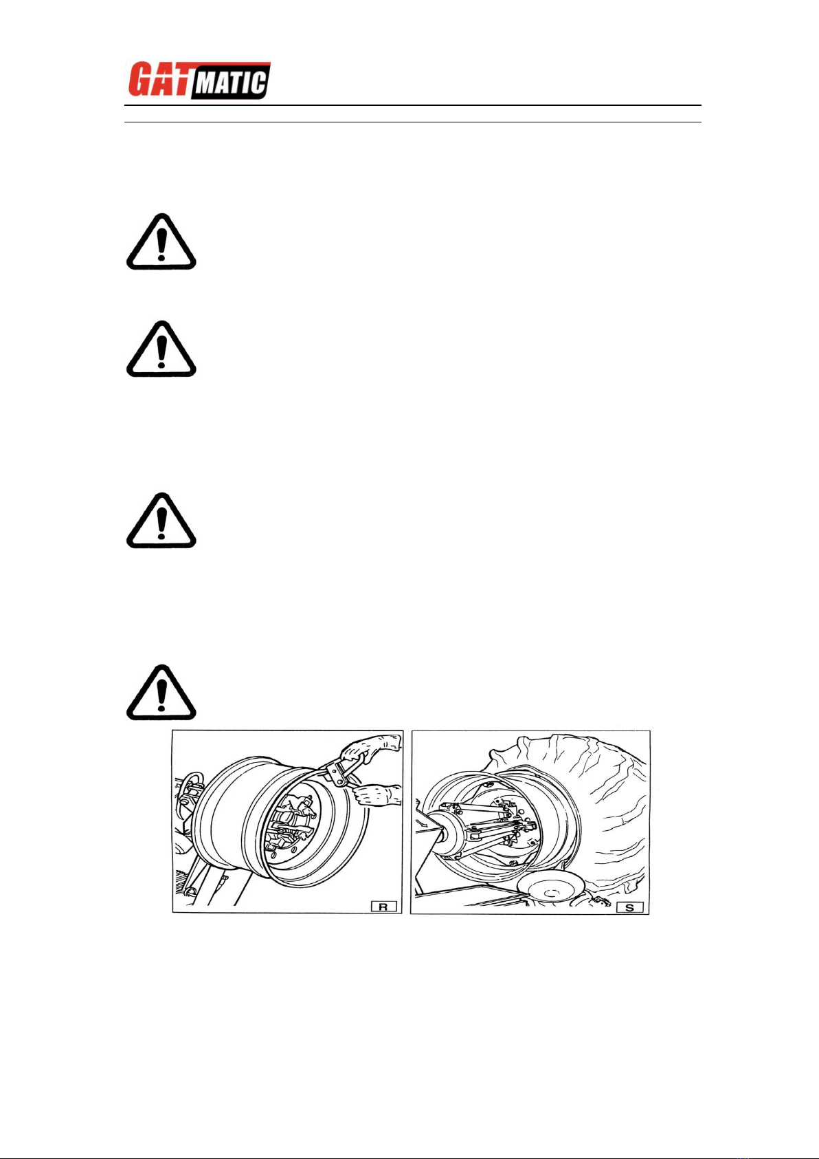
3) Attach the RP clip to the outside edge of the rim at the highest point (see Fig.
R).
4) Put the tire on the platform and lower the spindle (make sure the clip is at
the high point) to hook the first bead on the clip.
5) Lift the rim with the tire hook to it and turn it anticlockwise about 15-20 cm.
The tire will be positioned tilted across the rim.
Take the mobile control unit to work position D.
Take the mobile control unit to work position B.
DANGER!
When the beads come off the rim, the wheel will fall. Check to
make sure there are no by-standers in the work area.
CAUTION!
Make sure the clip is firmly attached to the rim.
Take the mobile control unit to work position B.
TIRE CHANGER FOR TRUCK TWC-1600
17
6) Move the tool carrier arm to its non-working position. Move it to the inside
plane of the tire and rehook it in this position.
7) Check to make sure the hook tool is positioned on the wheel side. If not,
press lever (19,Fig.D)and turn it 180º.
8) Move the tool forward until the red reference dot is lined up with the outside
edge of the rim and about 5 mm from it(see Fig.S)
9) Move to the outside of the wheel and check the exact position of the hook
visually and adjust it as needed. Then turn the spindle clockwise until the
clip is at the bottom (6 o’clock). The first bead will be on the rim. Remove the
clip.
10) Remove the tool from the tire.
11) Move the tool carrier arm to its non-working position. Move it to the outside
plane of the tire.
12) Turn the tool 180º with lever(19,Fig.D)
13)Turn the spindle until the valve hole is at the bottom (6 o’clock).
14)Move the platform (4 Fig. A) under the wheel and lower the spindle until the
tire is pressed down against the platform. As the platform is moved slightly
towards the outside, the tire will open a little and thus create enough space
to insert the inner tube.
NB: The valve hole may be asymmetrical to the center of the rim. In this
case position and insert the inner tube as shown in Fig .T.
Take the mobile control unit to work position D.
Take the mobile control unit to work position C.
Take the mobile control unit to work position D.
Take the mobile control unit to work position B.

TIRE CHANGER FOR TRUCK TWC-1600
18
Insert the valve through the hole and fix it with its locking ring.
15)Place the inner tube in the center well of the rim (NB: to facilitate this, turn
the spindle clockwise).
16)Turn the spindle until the valve is at the bottom (6 o’clock).
17)Inflate the inner tube a little (until it has no folds) so as not to pinch it while
mounting the second bead.
18)Attach an extension to the valve and then remove the locking ring.
NB: The purpose of this operation is to allow the valve to be loose so that
it is not ripped out during second bead mounting.
19)Move the tool carrier arm (14, Fig. D) to its working position.
20) Bring the tool forward until the red reference dot is lined up with the outside
edge of the rim and about 5 mm from it.
21)Pull back on this lever which will guide the bead into center well. Continue to
turn the spindle until the tire is completely mounted on the rim.
22)Tip the tool carrier arm to its non-working position.
23)Position the platform directly under the wheel and lower the spindle until the
wheel rests on the platform.
24) When the wheel is resting on the platform, check to make sure the valve is
perfectly centered with its hole. If it is not, turn the spindle slightly to adjust
the position. Fix the valve with its locking ring and remove the extension.
25) Close the arms of the spindle completely. Support the wheel to prevent it
falling off.
26) Move the platform to release the wheel from the spindle.
27) Remove the wheel.
Take the mobile control unit to work position C.
DANGER!
This operation can be extremely dangerous.
Do it manually only if you are certain you can keep the wheel
balanced.
For large and heavy tires an adequate lifting device must be used.
TIRE CHANGER FOR TRUCK TWC-1600
19
WHEELS WITH SPLIT RING BEAD BREAKING AND DEMOUNTING
WHEELS WITH 3-PIECE RINGS
1) Clamp the wheel on the spindle as described previously and check to make
sure it has been deflated.
3) Lower the tool carrier arm (14, Fig. D) to its work position until it is locked in
position by its hook.
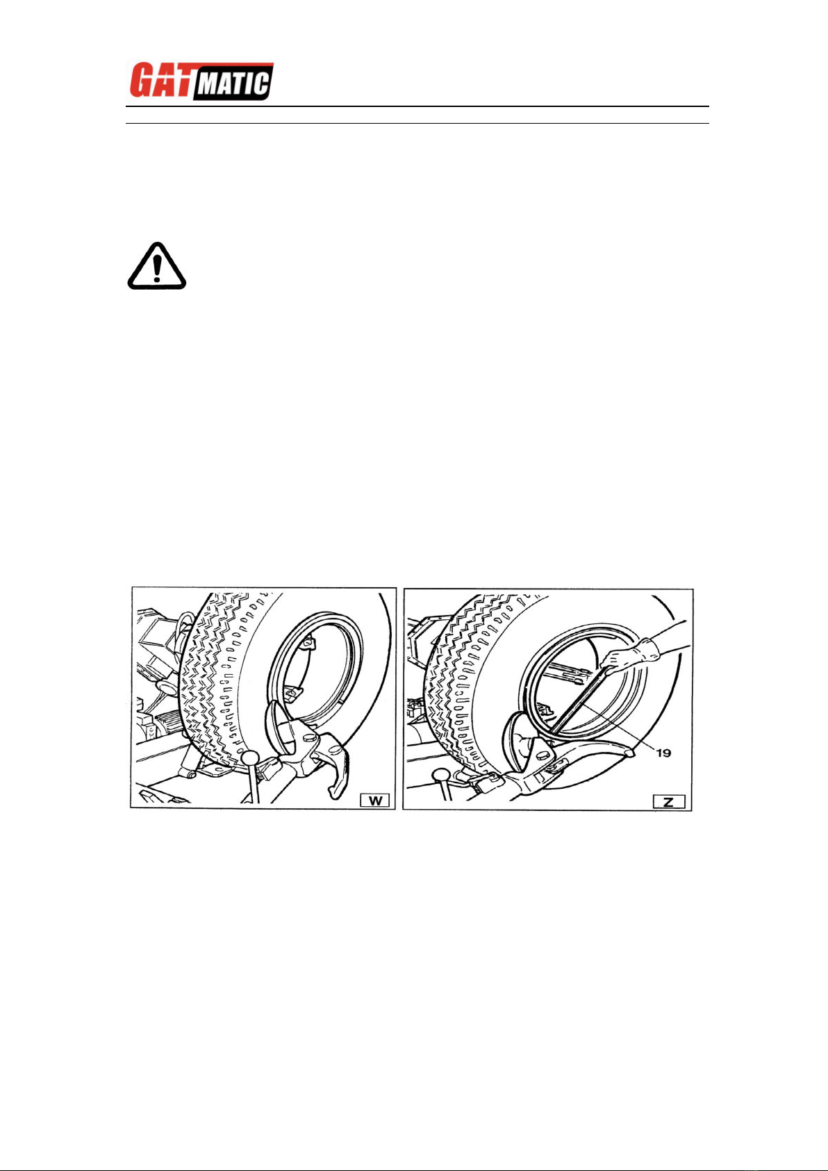
4) Position the bead loosener disk level with the rim (see Fig. W.)
5) Turn the spindle and at the same time move the disk forward a bit at a time
following the contour of the rim until the first bead is completely free (NB:
lubricate while doing this).
CAUTION! If the tire has an inner tube, work very carefully and be prepared to
stop the disk immediately once the bead has been broken so as not to damage
the valve and the inner tube.
6) Repeat this procedure but this time bring the disk against the split-ring (see
Fig. Z) until the lock ring is freed. Remove this with the special lever TL (19
Fig. Z) or with the help of the disk.
7) Remove the split-ring.
8) Move the tool carrier arm (14 Fig. D) back from the edge of the rim. Release
the hook and tip the arm to its non-working position.
Move the tool carrier arm to the inside plane of the wheel.
9) Press lever (19 Fig. D) and turn the tool head 180º which will automatically
lock in this position. Lower the arm to its working position.
10)Turn the spindle and at the same time bring the bead loosener disk up
against the tire following the contour of the split-ring until the second bead
has been broken(NB: Lubricate during this process).Continue to move
the disk forward until about half the tire has demounted from the rim(see Fig.
K).
11) Move the tool carrier arm to its non-working position.
12) Move the platform(4 Fig. A) directly under the wheel .
2) Take the mobile control unit to work position B.
Table of contents


