Keba KeContact P20 User manual

Standsäule
Installationsanleitung
Deutsch
(5)
Floor-mounted column
Installation Manual
English
(11)
Colonne
Manuel d'installation
Français
(17)
Poste
Instrucciones de instalación
Español
(23)
Colonnina portante
Istruzioni per l'installazione
Italiano
(29)
Standzuil
Installatiehandleiding
Nederlands
(35)
Coluna vertical
Instruções de instalação
Português
(41)
Specifications are subject to change due to further technical developments. Details present-
ed may be subject to correction. All rights reserved.
All intellectual property, including trademarks and copyrights, is the property of the respecti-
ve owner. Any unauthorized use of such intellectual property is expressly forbidden.
Floor-mounted column - Installation Manual, v4.00, 90333

2 Floor-mounted column – Installation Manual, v4.00, 90333
V1

Floor-mounted column – Installation Manual, v4.00, 90333 3
V2

4 Floor-mounted column – Installation Manual, v4.00, 90333
V3

DE
Floor-mounted column – Installation Manual, v4.00, 90333 5
Standsäule – Installationsanleitung
Sicherheitshinweise
!
WARNUNG!
Nichtbeachtung der Sicherheitshinweise kann zu Lebensgefahr, Verletzungen und
Schäden am Gerät führen! Der Hersteller lehnt jede Haftung für daraus resultieren-
de Ansprüche ab!
Elektrische Gefahr!
Die Montage, erste Inbetriebnahme und Wartung der Ladestation darf nur von
einer einschlägig ausgebildeten, qualifizierten und befugten Elektrofachkraft
durchgeführt werden, die dabei für die Beachtung der bestehenden Normen
und Installationsvorschriften verantwortlich ist.
Halten Sie die angeführten Vorgaben für die Standortauswahl und die bauli-
chen Voraussetzungen ein!
Abweichungen zu den Standortvorgaben können zu Tod, schweren Körperver-
letzungen oder Sachschäden führen, wenn die entsprechenden Vorsichtsmaß-
nahmen nicht getroffen werden!
Gebrauch dieses Handbuchs
Dieses Installationshandbuch wendet sich ausschließlich an qualifiziertes Personal1.
Diese Anleitung ist eine Ergänzung zum „Installationshandbuch“ der Ladestation. Alle im
Handbuch enthaltenen Hinweise und Anweisungen zu Standortauswahl, Montage und zum
Anschluss der Ladestation müssen beachtet werden!
Bestimmungsgemäßer Gebrauch
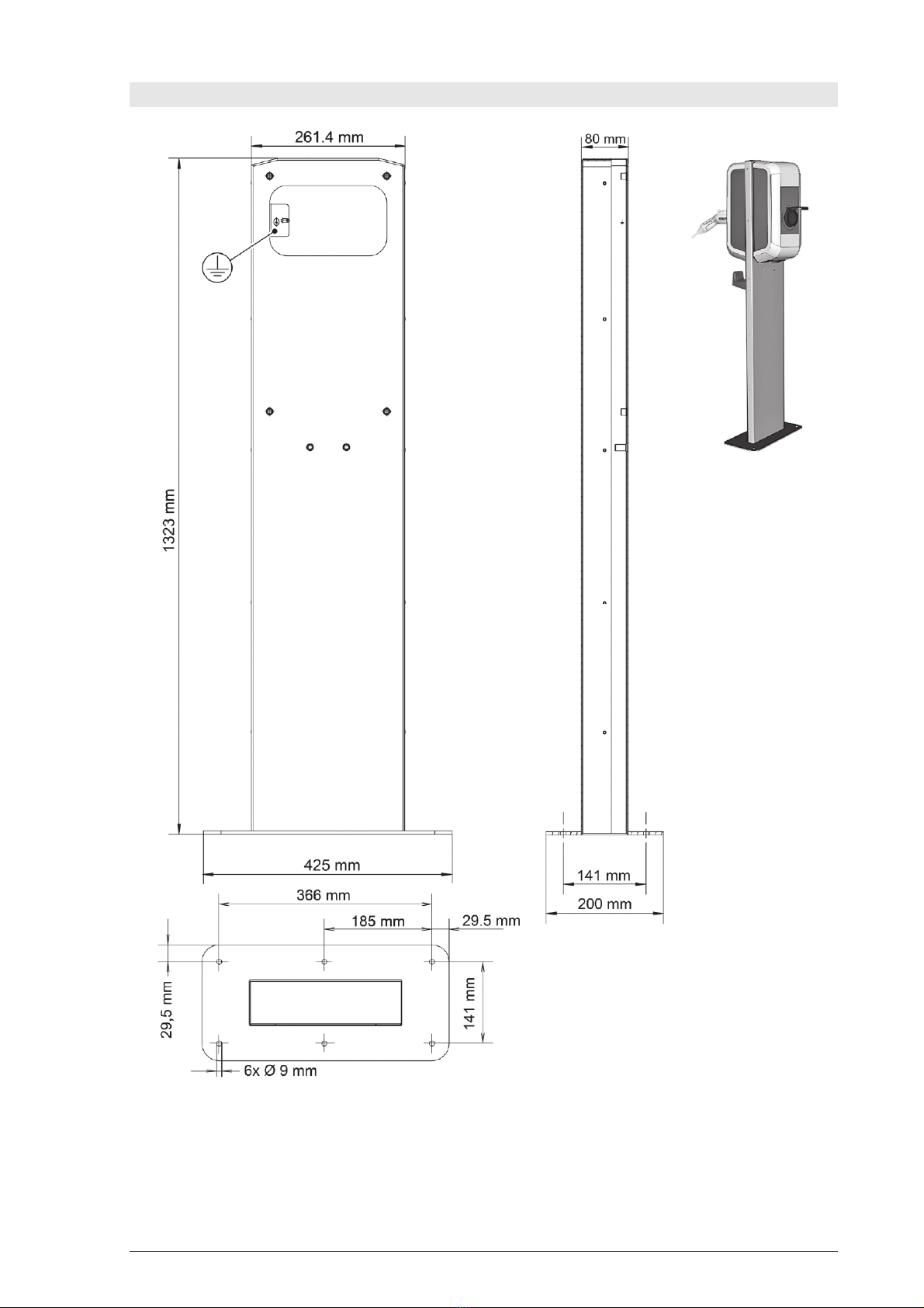
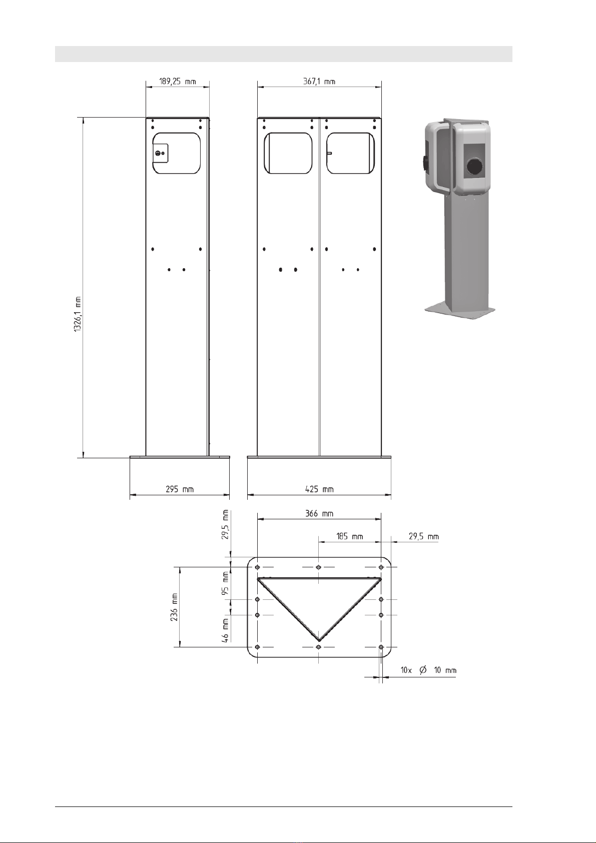
Alternativ zur Montage der Ladestation auf einer Wand, steht eine Standsäule zur freiste-
henden Montage im Innen- oder Außenbereich zur Verfügung.
Je nach Ausführung und Anzahl der Ladestationen muss eine unterschiedliche Anzahl von
Anschlusskabeln und Leerrohren im Betonfundament berücksichtigt werden.
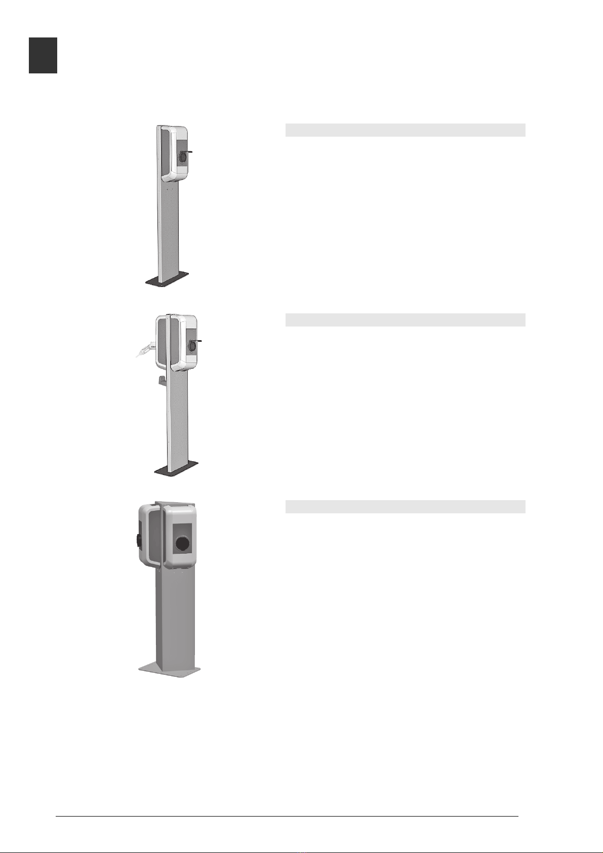
Wird die Ladestation mit einer steckbaren Versorgungsleitung installiert (z.B. für Demonstra-
tionszwecke), ist für die Versorgungsleitung eine ausreichende Zugentlastung sowie ein Kan-
tenschutz vorzusehen.
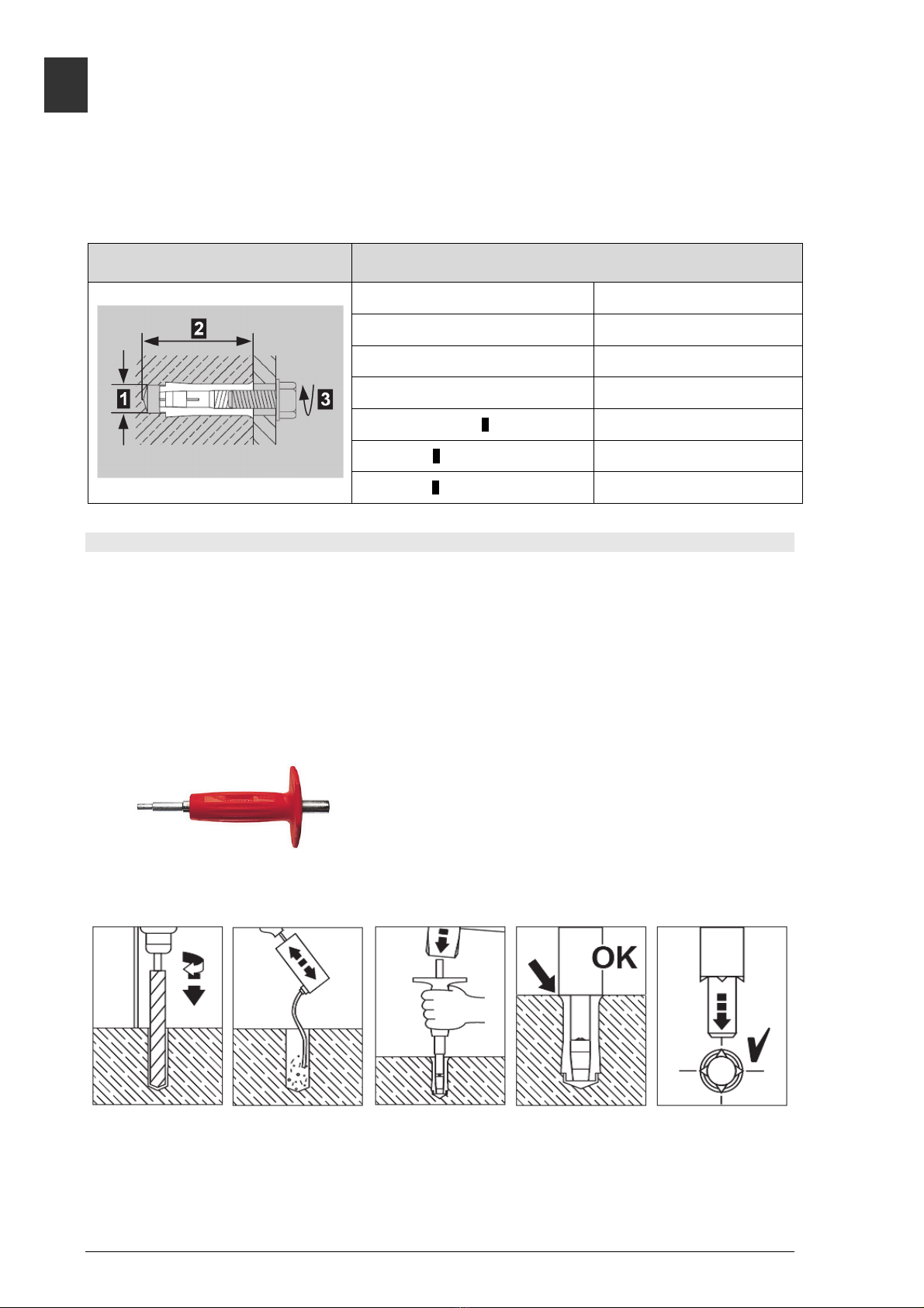
Für die Montage der Standsäule sind die jeweiligen nationalen Vorschriften zu beachten.
Gewicht (ohne Ladestation): 15,0 kg (V1/V2)
19,2 kg (V3)
1Personen die aufgrund fachlicher Ausbildung, Kenntnis und Erfahrung sowie Kenntnis der einschlägigen Nor-
men, die übertragenen Arbeiten beurteilen und mögliche Gefahren erkennen können.

DE
6 Floor-mounted column – Installation Manual, v4.00, 90333
Übersicht
Standsäule V1
Die Standsäule V1 ist für die Montage von
einer Ladestation auf der Standsäule geeignet.
Standsäule V2
Die Standsäule V2 ist für die Montage von zwei
Ladestationen auf der Standsäule geeignet.
Standsäule V3
Die Standsäule V3 ist für die Montage von zwei
Ladestationen auf der Standsäule geeignet.

DE
Floor-mounted column – Installation Manual, v4.00, 90333 7
!
WARNUNG!
Elektrische Gefahr!
Die Standsäule V2/V3 muss immer
mit zwei Ladestationen bestückt
werden! Kabelöffnungen in der
Standsäule dürfen nicht offen blei-
ben.
Anforderungen an den Standort
Allgemeines:
Alle Standortanforderungen für die Ladestation aus dem „Installationshandbuch“
der Ladestation müssen beachtet werden!
Bei der Montage der Standsäule auf Parkplätzen oder in Tiefgaragen ist bauseits ein
geeigneter Anfahrschutz vorzusehen.
Betonfundament:
Die Berechnung, Auslegung und Herstellung des Betonfundaments liegt im Verantwor-
tungsbereich des Standortherstellers.
Für die Aufstellung ist waagrechter, ebener und tragfähiger Untergrund erforderlich.
Um eine sichere und dauerhafte Verankerung zu gewährleisten, empfehlen wir die Aus-
führung eines Betonfundaments:
65 cm (L) x 50 cm (B), Tiefe = mind. Frostgrenze jedoch > 40 cm, frostsicher gegründet.
Beton: C30/37 LP für XC4, XD1, XF4 bzw. C25/30 LP für XC4, XD1, XF2
Betonstahl: BSt 500 S; BSt 500 M
Der Untergrund muss das Ablaufen von eventuell in den Sockel gelangendem Wasser
ermöglichen.
Alle Kabel müssen genau in der Mitte des Betonfundaments aus dem Boden geführt
werden und für die weitere Montage eine Überlänge von ca. 1,5 m aufweisen.
Bei der Herstellung des Betonfundaments sind die Kabel mit geeigneten Mitteln gegen
Beschädigungen zu schützen (z.B. mit einem Schutzschlauch). Der Schutzschlauch
muss eine Überlänge von ca. 25 cm über dem Betonfundament aufweisen.
Eine Aufstellung der Standsäule auf Asphalt ist nicht zulässig!

DE
8 Floor-mounted column – Installation Manual, v4.00, 90333
Verankerung am Boden
Zum Verankern müssen die beigelegten Dübel verwendet werden (6 Stück Kompaktdübel
Hilti HKD-ER M8x30).
Spezifikation Kompaktdübel Hilti
HKD-ER M8x30 (Quelle: Fa. Hilti) Technische Daten
Ankergrund Normbeton ab Festigkeitsklasse
C20/25-C50/60
Empfohlene Last Zug N
(ungerissener Beton) 4 kN
Querzug V pro Dübel
(ungerissener Beton) 3,9 kN
Erforderlicher Randabstand 10,5 cm
Bohrlochdurchmesser 1 10 mm
Bohrlochtiefe 2 33 mm
Drehmoment 3≥8 Nm
Bohrungen durchführen
►Zeichnen Sie die 6 Bohrungen mit Hilfe der Bodenplatte der Standsäule auf dem
Betonfundament an.
Stellen Sie sicher, dass sich die Anschlusskabel genau unter der Öffnung der
Bodenplatte der Standsäule befinden.
►Bohren Sie die 6 Befestigungslöcher:
Durchmesser: 10 mm
Bohrlochtiefe: 33 mm
►Schlagen Sie die beigepackten Dübel mit dem Hilti HSD-G Hand-Setzwerkzeug (nicht
im Lieferumfang) so weit ein, dass sie mit dem Boden eben abschließen.
Hilti HSD-G Hand-Setzwerkzeug (Quelle: Fa. Hilti)
Beachten Sie auch die folgende Anleitung:
Anleitung zum Setzen der Dübel (Quelle: Fa. Hilti)

DE
Floor-mounted column – Installation Manual, v4.00, 90333 9
Hinweis
Die Abbildungen gelten für alle Varianten.
Standsäule von unten
Kabel einfädeln
►Fädeln Sie die Anschlusskabel von unten
durch die Standsäule nach oben zur
Kabelöffnung.
Verankerung
Verankerung
►Positionieren Sie die Standsäule über
dem Kabelauslass.
►Verankern Sie die Standsäule mit den
6 Sechskantschrauben am Fundament.
Erdungspunkt
Erdung
►Schließen Sie (falls erforderlich) die
Erdung am Erdungspunkt der Standsäule
an.

DE
10 Floor-mounted column – Installation Manual, v4.00, 90333
Kantenschutz entfernen
►Entfernen Sie den Kantenschutz an der
Kabelöffnung der Standsäule erst
unmittelbar vor der Montage der
Ladestation (siehe Abbildung).
Beispiel Standsäule V2
Ladestationen montieren
►Montieren Sie die Ladestationen mit den
beiliegenden Schrauben auf der
Standsäule.
Anschluss und Inbetriebnahme
►Führen Sie den elektrischen Anschluss
und die Inbetriebnahme entsprechend der
Anleitung im „Installationshandbuch“ der
Ladestation durch.
Halterung für Ladekabel
Halterung für Ladekabel montieren (Option)
►Montieren Sie die Halterung für das
Ladekabel unterhalb der Ladestation mit
zwei Schrauben 1an der Standsäule.

EN
Floor-mounted column – Installation Manual, v4.00, 90333 11
Floor-mounted column – Installation Manual
Safety instructions
!
WARNING!
Not observing the safety instructions can result in risk of death, injuries and dam-
age to the device! The manufacturer assumes no liability for claims resulting from
this!
Electrical hazard!
The installation, commissioning and maintenance of the charging station may
only be performed by correctly trained, qualified and authorized electricians
who are fully responsible for the compliance with existing standards and in-
stallation regulations.
Observe the instructions given for selecting the location and the construction-
al requirements!
If the specifications for the location are not observed, this can result in death,
serious physical injury or equipment damage if the corresponding precaution-
ary measures are not met!
Use of this manual
This installation manual is intended for qualified personnel only2.
This manual is a supplement to the "Installation Manual" of the charging station. The infor-
mation and instructions in the manual about selecting the location, installation and connec-
tion of the charging station must be adhered to.
Intended use
A floor-mounted column for free-standing installation in inside or outside areas is available as
an alternative to mounting the charging station on a wall.
Depending on the design and number of charging stations the relevant number of empty
pipes and connection cables should be taken into consideration in the concrete foundation.
If the charging station is installed with a plug-in power supply line (e.g., for demonstration
purposes), you should ensure that there is sufficient tension relief and edge protection for the
power supply line.
The respective national regulations must be observed with regard to the installation of the
floor-mounted columns.
Weight (without charging station): 15,0 kg (V1/V2)
19,2 kg (V3)
2Persons who, due to their special training, expertise and experience as well as knowledge of current standards,
are able to assess the work performed and the possible hazards.

EN
12 Floor-mounted column – Installation Manual, v4.00, 90333
Overview
V1 floor-mounted column
The V1 floor-mounted column is designed for
the installation of one charging station on the
column.
V2 floor-mounted column
The V2 floor-mounted column is designed for
the installation of two charging stations on the
column.
V3 floor-mounted column
The V3 floor-mounted column is designed for
the installation of two charging stations on the
column.

EN
Floor-mounted column – Installation Manual, v4.00, 90333 13
!
WARNING!
Electrical hazard!
The V2/V3 floor-mounted column
must always be fitted with two
charging stations! There can be no
open cable openings in the column.
Location requirements
General:
All of the location requirements for the charging station in the "Installation Manu-
al" of the charging station must be adhered to!
When mounting the floor-mounted columns in parking spaces or parking garages, appro-
priate anti-collision protection must be provided by the customer.
Concrete foundation:
The calculation, design and manufacture of the concrete founcation lies in the scope of
responsibility of the producer of the site.
A horizontal, level and sound foundation is required for installation.
To ensure safe and permanent anchoring, we recommend creating a concrete founda-
tion:
65 cm (L) x 50 cm (W), depth = min. frost limit but > 40 cm, frost-free.
Concrete: C30/37 LP for XC4, XD1, XF4 or C25/30 LP for XC4, XD1, XF2
reinforced concrete: BSt 500 S; BSt 500 M
The base must permit the running off of any water that has entered the base.
All cables must be laid precisely in the centre of the concrete foundation from the base
and must have an excess length of approx. 1.5 m for the remaining installation activities.
During the production of the concrete foundation, the cables must be protected against
damage using appropriate measures (e.g., a protective tube). The protective tube must
have an excess length of approx. 25 cm above the concrete foundation.
Mounting the column on asphalt is not allowed!

EN
14 Floor-mounted column – Installation Manual, v4.00, 90333
Anchoring to the base
The enclosed dowels must be used for anchoring (6 x Hilti HKD-ER compact dowels M8x30).
Specifications for compact dowels Hilti
HKD-ER M8x30 (Source: Hilti) Technical data
Anchorage ground Standard concrete with a strength
class of C20/25-C50/60 or greater
Recommended load tension N
(uncracked concrete) 4 kN
Transversal shear V per dowel
(uncracked concrete) 3,9 kN
Required clearance 10,5 cm
Drill-hole diameter 1 10 mm
Drill-hole depth 2 33 mm
Torque 3≥8 Nm
Making drillholes
►Mark the 6 holes on the concrete foundation using the baseplate of the floor-mounted
column.
Make sure that the connection cable is located precisely underneath the opening in the
baseplate.
►Drill the 6 mounting holes:
Diameter: 10 mm
Drill-hole depth: 33 mm
►Hammer the enclosed dowels using the Hilti HSD-G manual setting tool (not included
in the scope of delivery) so that they are flush with the floor.
Hilti HSD-G manual setting tool (Source: Hilti)
Please also observe the following instructions:
Instructions on inserting the dowels (Source: Hilti)

EN
Floor-mounted column – Installation Manual, v4.00, 90333 15
Note
The images are valid for all versions.
Floor-mounted column from below
Thread in cable
►Thread the connection cables from the
bottom through the column upwards
through the cable opening.
Anchoring
Anchoring
►Position the column directly over the
cable outlet.
►Anchor the column to the foundation
using the 6 hexagon bolts.
Grounding point
Grounding
►If necessary, connect the earthing to the
column's grounding point.

EN
16 Floor-mounted column – Installation Manual, v4.00, 90333
Remove edge protection
►Remove the edge protection on the cable
opening of the column immediately before
installing the charging station (see figure).
V2 floor-mounted column example
Mounting the charging stations
►Mount the charging stations on the
column using the enclosed screws.
Connecting and commissioning
►Perform the electrical connection and
commissioning in accordance with the
instructions in the "Installation Manual" of
the charging station.
Holder for charging cable
Mount the holder for the charging cable
(option)
►Mount the holder for the charging cable
on the floor-mounted column below the
charging station using two screws 1.

FR
Floor-mounted column – Installation Manual, v4.00, 90333 17
Colonne – Manuel d'installation
Consignes de sécurité
!
AVERTISSEMENT !
Le non-respect des consignes de sécurité peut entraîner la mort, des blessures ou
l’endommagement de l’appareil ! Le fabricant décline toute responsabilité pour les
demandes qui en résulteraient !
Danger électrique !
Le montage, la première mise en service et la maintenance de la station de re-
charge doivent être confiés uniquement à un électricien compétent, qualifié et
autorisé qui porte l’entière responsabilité du respect des normes et des pres-
criptions d’installation existantes.
Tenir compte des informations suivantes dans le choix du site et respecter les
conditions structurelles !
Toute différence peut entraîner la mort, des blessures graves ou des dom-
mages matériels si les mesures de sécurité correspondantes ne sont pas
prises !
Utilisation de ce manuel
Ce manuel d’installation s’adresse exclusivement au personnel qualifié3.
Ce manuel complète le « Manuel d'installation » de la station de recharge. Respecter les
consignes et les instructions du manuel en ce qui concerne le choix du site, le montage et le
raccordement de la station de recharge !
Utilisation conforme
L'alternative au montage mural de la station de recharge est le montage isolé sur colonne à
l'intérieur ou à l'extérieur.
Selon le modèle et le nombre de stations de recharge, le nombre de câbles de raccordement
et de gaines dans la fondation en béton varie.
Si la station de recharge est installée avec un câble d'alimentation enfichable (par ex. à des
fins de démonstration), prévoir une décharge de traction suffisante et une protection de bord
pour le câble d'alimentation.
Respecter la réglementation nationale en vigueur pour le montage de la colonne.
Poids (sans station de recharge): 15,0 kg (V1/V2)
19,2 kg (V3)
3Personnes qui, en raison de leur formation technique, de leurs connaissances, de leur expérience et de leur
connaissance des normes en vigueur, sont capables d'évaluer les travaux qui leur sont confiés et d'identifier les
dangers potentiels.

FR
18 Floor-mounted column – Installation Manual, v4.00, 90333
Aperçu
Colonne V1
La colonne V1 convient au montage d'une
station de recharge.
Colonne V2
La colonne V2 convient au montage de deux
stations de recharge.
Colonne V3
La colonne V3 convient au montage de deux
stations de recharge.

FR
Floor-mounted column – Installation Manual, v4.00, 90333 19
!
AVERTISSEMENT !
Danger électrique !
La colonne V2/V3 doit toujours être
équipée de deux stations de re-
charge ! Les ouvertures de câble de
la colonne ne doivent pas rester
ouvertes.
Exigences sur site
Généralités
Respecter toutes les exigences relatives au site pour la station de recharge qui
figurent dans le « Manuel d'installation » de la station de recharge !
Si la colonne est installée dans un parking ou dans un garage souterrain, prévoir une
protection contre les collisions adaptée.
Fondation en béton
Le constructeur du site est responsable de l'élaboration, de la conception et de la cons-
truction de la fondation en béton.
L'installation exige un support horizontal, plan et résistant.
Pour garantir un ancrage sûr et durable, construire une fondation en béton ingélive dont
les caractéristiques sont les suivantes :
65 cm (longueur) x 50 cm (largeur), profondeur = au moins limite du gel mais > 40 cm.
Béton : C30/37 LP pour XC4, XD1, XF4 ou C25/30 LP pour XC4, XD1, XF2
Béton armé : BSt 500 S ; BSt 500 M
La fondation doit permettre l'évacuation de l'eau éventuellement présente dans la se-
melle.
Tous les câbles doivent ressortir du sol exactement au milieu de la fondation en béton et
dépasser d'env. 1,5 m pour poursuivre le montage.
Lors de la construction de la fondation en béton, protéger les câbles contre les dom-
mages à l'aide d'accessoires adaptés (par ex. une gaine). La gaine doit dépasser de la
fondation en béton d'env. 25 cm.
L'installation de la colonne sur l'asphalte n'est pas autorisée !

FR
20 Floor-mounted column – Installation Manual, v4.00, 90333
Ancrage au sol
Pour l'ancrage, utiliser les chevilles fournies (6 chevilles compactes Hilti HKD-ER M8x30).
Spécifications des chevilles compactes
Hilti HKD-ER M8x30 (Source : Sté Hilti) Caractéristiques techniques
Support d'ancrage Béton normalisé à partir de la
classe de résistance C20/25-C50/60
Charge recommandée - traction N
(béton non fissuré) 4 kN
Traction transversale V par cheville
(béton non fissuré) 3,9 kN
Distance du bord nécessaire 10,5 cm
Diamètre de perçage 1 10 mm
Profondeur de perçage 2 33 mm
Couple de serrage 3≥8 Nm
Exécution des perçages
►Sur la fondation en béton, tracez les 6 perçages à l'aide du socle de la colonne.
Assurez-vous que les câbles de raccordement se trouvent exactement sous l'ouverture
du socle de la colonne.
►Percez les six trous de fixation :
Diamètre: 10 mm
Profondeur du perçage: 33 mm
►Insérez les chevilles fournies avec l'outil de pose manuel Hilti HSD-G (non fourni)
jusqu'à ce qu'elles touchent le sol.
Outil de pose manuel Hilti HSD-G (Source : Sté Hilti)
Respectez également les instructions suivantes :
Instructions pour la pose des chevilles (Source : Sté Hilti)
Other manuals for KeContact P20
10
This manual suits for next models
1
Table of contents
Languages:
Other Keba Automobile Accessories manuals