manuals.online logo
Brands
  1. Home
  2. •
  3. Brands
  4. •
  5. Scosche
  6. •
  7. Automobile Accessories
  8. •
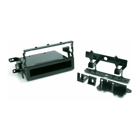
  9. Scosche MA2030 User manual

Scosche MA2030 User manual

IN-DASH INSTALLATION KIT FOR
1984-UP MAZDA VEHICLES
MA2030MA2030
MA2030MA2030
MA2030
Thank you for purchasing the Scosche MA2030 Kit. This kit was manufactured with the highest of quality
standards.
CAUTION:
DISCONNECT YOUR VEHICLE'S NEGATIVE BATTERY TERMINAL BEFORE THE INSTALLATION TO HELP PREVENT
ELECTRICAL DAMAGE. WE RECOMMEND THE USE OF A VOLT/OHM METER OVER A TEST LIGHT TO CHECK
WIRING. A TEST LIGHT OR GROUNDED WIRE PROBE CAN CAUSE DAMAGE TO THE VEHICLE'S COMPUTER AND/
OR DIAGNOSTIC SYSTEMS. AVOID ALL FACTORY AIR BAG WIRING - AIR BAGS CAN ACCIDENTALLY DEPLOY
CAUSING SERIOUS INJURY OR DEATH.
NOTES:
•See your vehicle's instructions for any special tools your installation might require.
•Read all instructions accompanying your car stereo/cassette player for proper wiring and mounting instructions.
INTRODUCTION / PRELIMINARY
PANEL A
PANEL B
PRELIMINARY PARTS LIST
Your kit includes:
• 1 Mounting Panel A • 1 Mounting Panel B • 1 Mounting Panel C • 1 Trim Panel F
• 1 Trim Panel G • 1 Trim Panel E • 1 Panel Spacer D • 20 Brackets (A-S)
• 2 Spacers • Mounting Hardware • Instruction Book
ASSEMBLING THE KIT
This kit can be assembled in several different configurations, first refer to the applications
list to find your vehicle and then follow the listed directions.
ATTACHING THE PANELS
Some installations require two or more panels to be attached together. To attach panels
together, simply line up the tabs and slots between the kit panels and press them together.
(See illustration A.)
ATTACHING THE BRACKETS
Some installations require that you attach
specific brackets to the mounting panels.
Before attaching bracket to the top,
bottom, or sides of the mounting panels,
there are molded-on numbered tabs that will
have to be removed. Use cutters or
simply bend the tabs back and forth until they
come off. (See illustration B.)
PANEL B
PANEL A
ILLUSTRATION A
BRACKET A
ILLUSTRATION B
NUT
USE THE SHADED TABS AND
CUT OFF THE REMAINING
NUT
BRACKET O
BRACKET O
HOLE #2 CINCH STUDS
CINCH STUDS
DIN RADIO INSTALLATION (DETACHABLE FACE/PULLOUT)
Before installing a DIN radio, the shaft support sections of panel A or C need to
be removed. Remove the front panel shaft sections as shown. Following the
cut lines with side cutters, an X-acto knife, a hacksaw blade or wire cutters
and cut out the two sections. Use caution with sharp tools
and cut away from yourself. Insert the DIN radio’s mounting
sleeve and bend the tabs as shown.
MOUNTING THE RADIO
RADIO’S
SUPPLIED
TRIMPLATE DIN RADIO
MOUNTING
PANELS A & B
RADIO SLEEVE
CUT BRACES OUT
REAR SUPPORT STRAP
DIN CUT LINES
(REAR VIEW OF KIT)
1986-93 Mazda B2000
USE THE SHADED BRACKETS & THE INDICATED HOLE LOCATIONS. CUT OFF THE REMAINING BRACKETS AND DISCARD.
SIDE VIEW
CUT
FRONT VIEW
PANEL B
PANEL A
USE BRACKET 4
CUT
BRACKET F
USE HOLE 5
USE
BRACKET 4
BRACKET G USE HOLE 6
1989-95 Mazda MPV (Van)
Radio Removal:
1. Remove the ashtray, then extract two screws
from this location.
2. Carefully release the trim panel fasteners and
pull back the trim panel, disconnect the lighter
connectors and remove the trim.
3. Extract four screws securing the radio to the
dash - two located at the top and two at the
bottom.
4. Pull the radio out of the cavity, disconnect the
wire harness, then remove the radio.
USE THE SHADED BRACKETS & THE INDICATED HOLE LOCATIONS. CUT OFF THE REMAINING BRACKETS AND DISCARD.
CUT OFF AT THE SECOND CUT LINE FROM THE TOP.
CUTLINES ARE ON THE BACK OF THE PANEL
FRONT VIEW
PANEL A
SIDE VIEW
TRIM PANEL E
USE BRACKET 1
BEND TABS
OUTWARD
1990-97 Mazda Miata
Radio Removal:
1. Open the center console
storage opening and extract
the two screws from this location.
2. Pull out the ashtray and remove the
single screw from this location.
3. Remove one screw from each side of
center console (two screws total), located
along front portion of console.
4. Take off the shift knob and remove
the center console from the car.
5. Extract the single screw from the lower
left side of the radio console.
6. Carefully pop out the air vents, gently pry at each side to release the spring type securing clips.
7. Remove one screw from behind each vent location (two screws total).
8. Remove the radio console trim panel.
9. Extract the four screws securing the factory radio to the dash. Pull the unit out of the cavity, disconnect all connectors,
then remove the radio.
USE
BRACKET R
WITH HOLE 1
PANEL A
USE BRACKET S WITH HOLE 1
TOP VIEW USE BRACKET S
WITH HOLE 1
PANEL B USE BRACKET A
WITH HOLE 6
SIDE VIEW
FRONT VIEW
CUT
USE BRACKET A WITH HOLE 6
Radio Removal:
1. Remove ashtray, then remove one 10mm
hex head screw from behind.
2. Remove two Phillips head sheet
metal screws from each side
of console.
3. Pull console away from mounting
position and disconnect four
electrical plugs.
4. Radio is secured to console from
behind. Remove four Phillips head sheet
metal screws which secure radio/bracket assembly to console
shell and two from above radio. Slide radio assembly out of console shell.
CAUTION:
REAR SUPPORT AVAILABLE
SEPARATELY. REAR SUPPORTING
THE RADIO ADDS TO THE
INSTALLATIONS STRUCTURAL
INTEGRITY.
USE BRACKET R
WITH HOLE 1
USE THE SHADED BRACKETS & THE INDICATED HOLE LOCATIONS. CUT OFF THE REMAINING BRACKETS AND DISCARD.
1988-92 Mazda MX-6 (Coupe)
1988-92 Mazda 626 (Sedan)
Radio Removal:
1. Remove ashtray and pocket. (Pocket slides out.)
2. Remove four Phillips head sheet metal screws securing
the radio trimpanel, two from the ashtray location and
two from the pocket location.
3. Carefully, remove the radio trimpanel, disconnect the
illumination light, the lighter plug, then
remove the trimpanel.
4. Remove four Phillips head sheet metal screws securing
the radio/EQ, pull radio out, disconnect antenna lead,
wire harnesses, then remove radio.
PANEL A
SIDE VIEW
USE BRACKET 5
USE BRACKET 3 WITH SPACER
USE BRACKET 5
FRONT VIEW
TRIM PANEL E CUT OFF AT THE SECOND CUT LINE FROM TOP.
CUTLINES ARE ON THE BACK OF PANEL
USE THE SHADED BRACKETS & THE INDICATED HOLE LOCATIONS. CUT OFF THE REMAINING BRACKETS AND DISCARD.
1986-92 Mazda RX-7
Radio Removal:
1. Carefully, pry up on the shifter
trimplate to release snap clips
and move trim towards rear
of car.
2. Remove ashtray and extract
two screws from behind the
ashtray.
3. Gently, pull bottom of radio trimpanel
away from dash.
4. Reach behind right lower corner of the
trim panel and disconnect the slip-on
terminal and the twist-type light socket
from the cigarette lighter.
5. Gently, pull bottom of the ventilation duct
trim away from the dash to access metal
clips which are located on each side of the
duct. Insert a thin metal strip (feeler gauge,
metal ruler, etc.) along each side of the trim
to release the clips.
6. Remove two screws from behind the duct
trim at the top of the radio trimpanel.
Carefully (evenly) pull the radio trimpanel
away from the dash to release the metal
clips and remove the radio trim.
7. Remove four screws which secure radio to dash, slide radio out of dash cavity, disconnect wiring harness and antenna
lead. Remove radio.
USE THE SHADED BRACKETS & THE INDICATED HOLE LOCATIONS. CUT OFF THE REMAINING BRACKETS AND DISCARD.
1984-85 Mazda RX-7 (Coupe)
USE THE SHADED BRACKETS & THE INDICATED HOLE LOCATIONS. CUT OFF THE REMAINING BRACKETS AND DISCARD.
Radio Removal:
1. Using panel removal tool, carefully pry up on
edges of trimpiece which covers
shift lever to release snapclips, lift
trimpiece up and rotate trim 90
degrees.
2. Remove two Phillips head sheet metal screws
from bottom of radio trimpanel.
3. Remove two air-conditioning control knobs, then
remove two shaftnuts from air-conditioning shafts.
4. Remove radio trimpanel.
5. Remove four Phillips head sheet metal screws
which secure radio equalizer assembly to dashboard,
then slide radio assembly out of dash.
6. Disconnect power antenna, speaker and all electrical
connections, then remove radio.
USE BRACKET 4
WITH SPACER
USE BRACKET A HOLE 4
PANEL A
PANEL B
CUT
SIDE VIEW
FRONT VIEW BOTTOM VIEW
USE BRACKET 4 WITH SPACER
BRACKET G
HOLE 4
BRACKET C
HOLE 7 WITH SPACER
BRACKET B
HOLE 7 WITH SPACER
PANEL A
BRACKET C
HOLE 7 WITH
SPACER
TOP VIEW
BRACKET B
HOLE 7 WITH
SPACER
FRONT VIEW
BOTTOM VIEW
CUT
CUT
PANEL B
BRACKET G
HOLE 4
BRACKET F
HOLE 4
BRACKET F
HOLE 4
DIN RADIO INSTALLATION (DETACHABLE FACE/PULLOUT)
Before installing a DIN radio, the shaft support sections of panel A or C need to
be removed. Remove the front panel shaft sections as shown. Following the
cut lines with side cutters, an X-acto knife, a hacksaw blade or wire cutters
and cut out the two sections. Use caution with sharp tools
and cut away from yourself. Insert the DIN radio’s mounting
sleeve and bend the tabs as shown.
MOUNTING THE RADIO
RADIO’S
SUPPLIED
TRIMPLATE DIN RADIO
MOUNTING
PANELS A & B
RADIO SLEEVE
CUT BRACES OUT
REAR SUPPORT STRAP
DIN CUT LINES
(REAR VIEW OF KIT)
1986-93 Mazda B2000
USE THE SHADED BRACKETS & THE INDICATED HOLE LOCATIONS. CUT OFF THE REMAINING BRACKETS AND DISCARD.
SIDE VIEW
CUT
FRONT VIEW
PANEL B
PANEL A
USE BRACKET 4
CUT
BRACKET F
USE HOLE 5
USE
BRACKET 4
BRACKET G USE HOLE 6
1989-95 Mazda MPV (Van)
Radio Removal:
1. Remove the ashtray, then extract two screws
from this location.
2. Carefully release the trim panel fasteners and
pull back the trim panel, disconnect the lighter
connectors and remove the trim.
3. Extract four screws securing the radio to the
dash - two located at the top and two at the
bottom.
4. Pull the radio out of the cavity, disconnect the
wire harness, then remove the radio.
USE THE SHADED BRACKETS & THE INDICATED HOLE LOCATIONS. CUT OFF THE REMAINING BRACKETS AND DISCARD.
CUT OFF AT THE SECOND CUT LINE FROM THE TOP.
CUTLINES ARE ON THE BACK OF THE PANEL
FRONT VIEW
PANEL A
SIDE VIEW
TRIM PANEL E
USE BRACKET 1
BEND TABS
OUTWARD
1990-97 Mazda Miata
Radio Removal:
1. Open the center console
storage opening and extract
the two screws from this location.
2. Pull out the ashtray and remove the
single screw from this location.
3. Remove one screw from each side of
center console (two screws total), located
along front portion of console.
4. Take off the shift knob and remove
the center console from the car.
5. Extract the single screw from the lower
left side of the radio console.
6. Carefully pop out the air vents, gently pry at each side to release the spring type securing clips.
7. Remove one screw from behind each vent location (two screws total).
8. Remove the radio console trim panel.
9. Extract the four screws securing the factory radio to the dash. Pull the unit out of the cavity, disconnect all connectors,
then remove the radio.
USE
BRACKET R
WITH HOLE 1
PANEL A
USE BRACKET S WITH HOLE 1
TOP VIEW USE BRACKET S
WITH HOLE 1
PANEL B USE BRACKET A
WITH HOLE 6
SIDE VIEW
FRONT VIEW
CUT
USE BRACKET A WITH HOLE 6
Radio Removal:
1. Remove ashtray, then remove one 10mm
hex head screw from behind.
2. Remove two Phillips head sheet
metal screws from each side
of console.
3. Pull console away from mounting
position and disconnect four
electrical plugs.
4. Radio is secured to console from
behind. Remove four Phillips head sheet
metal screws which secure radio/bracket assembly to console
shell and two from above radio. Slide radio assembly out of console shell.
CAUTION:
REAR SUPPORT AVAILABLE
SEPARATELY. REAR SUPPORTING
THE RADIO ADDS TO THE
INSTALLATIONS STRUCTURAL
INTEGRITY.
USE BRACKET R
WITH HOLE 1
USE THE SHADED BRACKETS & THE INDICATED HOLE LOCATIONS. CUT OFF THE REMAINING BRACKETS AND DISCARD.
SCOSCHE STEREO INSTALLATION COMPONENTS STEREO DASH KITS
Other Scosche Automobile Accessories manuals

Scosche TIQ01 User manual

Scosche

Scosche TIQ01 User manual

Scosche reVOLT USBC202M User manual

Scosche

Scosche reVOLT USBC202M User manual

Scosche ITCGM01AB User manual

Scosche

Scosche ITCGM01AB User manual

Scosche IDKCR01 User manual

Scosche

Scosche IDKCR01 User manual

Scosche MAGICMOUNT PRO User manual

Scosche

Scosche MAGICMOUNT PRO User manual

Scosche GOBAT 2600 PBC71 User manual

Scosche

Scosche GOBAT 2600 PBC71 User manual

Scosche BT1000 User manual

Scosche

Scosche BT1000 User manual

Scosche HAQ04 User manual

Scosche

Scosche HAQ04 User manual

Scosche HA1563B User manual

Scosche

Scosche HA1563B User manual

Scosche TA2121B User manual

Scosche

Scosche TA2121B User manual

Scosche HA1573 User manual

Scosche

Scosche HA1573 User manual

Scosche HY1602 User manual

Scosche

Scosche HY1602 User manual

Scosche SU2020 User manual

Scosche

Scosche SU2020 User manual

Scosche STUCKUP IUHW9R User manual

Scosche

Scosche STUCKUP IUHW9R User manual

Scosche MAGICMOUNT CHARGE User manual

Scosche

Scosche MAGICMOUNT CHARGE User manual

Scosche GM5201B User manual

Scosche

Scosche GM5201B User manual

Scosche e2 E2PM User manual

Scosche

Scosche e2 E2PM User manual

Scosche BlueFusion BFCL2K User manual

Scosche

Scosche BlueFusion BFCL2K User manual

Scosche DO2110 User manual

Scosche

Scosche DO2110 User manual

Scosche GMQ02 User manual

Scosche

Scosche GMQ02 User manual

Scosche WDQ2M User manual

Scosche

Scosche WDQ2M User manual

Scosche ITCFDOSB User manual

Scosche

Scosche ITCFDOSB User manual

Scosche SC-3000 User manual

Scosche

Scosche SC-3000 User manual

Scosche ITCFDOSAB User manual

Scosche

Scosche ITCFDOSAB User manual

Popular Automobile Accessories manuals by other brands

Haltech ic-7 quick start guide

Haltech

Haltech ic-7 quick start guide

Atwood APC45 Installation, operation and maintenance

Atwood

Atwood APC45 Installation, operation and maintenance

APS iArmor IA-S159 installation instructions

APS

APS iArmor IA-S159 installation instructions

Paxton Automotive Novi Supercharger 1200 Owner's installation guide

Paxton Automotive

Paxton Automotive Novi Supercharger 1200 Owner's installation guide

Menabo PROFESSIONAL FIX 605FP Fitting instructions

Menabo

Menabo PROFESSIONAL FIX 605FP Fitting instructions

STO N SHO SNS 33 Installation procedures

STO N SHO

STO N SHO SNS 33 Installation procedures

travall TDG 1304 FITTING INSTRUCTION

travall

travall TDG 1304 FITTING INSTRUCTION

BURY S8 Cradle Universal XXL Quick user guide

BURY

BURY S8 Cradle Universal XXL Quick user guide

Torklift D3102 installation instructions

Torklift

Torklift D3102 installation instructions

AMASE AUDIO BMW E46 7inch Android installation manual

AMASE AUDIO

AMASE AUDIO BMW E46 7inch Android installation manual

Havis-Shields Heavy Duty Trak Mount 2006-2009 Chevrolet Impala... Install instructions

Havis-Shields

Havis-Shields Heavy Duty Trak Mount 2006-2009 Chevrolet Impala... Install instructions

Unitech SU-V1B user manual

Unitech

Unitech SU-V1B user manual

Soundoff Signal intersector ENT2B3 Series quick start guide

Soundoff Signal

Soundoff Signal intersector ENT2B3 Series quick start guide

AeroForce interceptor user manual

AeroForce

AeroForce interceptor user manual

Directechs DB3 installation guide

Directechs

Directechs DB3 installation guide

Diode Dynamics DD0442 installation guide

Diode Dynamics

Diode Dynamics DD0442 installation guide

Safe Fleet Prime Design AR1221 manual

Safe Fleet

Safe Fleet Prime Design AR1221 manual

TEINHOF S-375 FITTING AND OPERATION MANUAL

TEINHOF

TEINHOF S-375 FITTING AND OPERATION MANUAL

manuals.online logo
manuals.online logoBrands
  • About & Mission
  • Contact us
  • Privacy Policy
  • Terms and Conditions

Copyright 2025 Manuals.Online. All Rights Reserved.