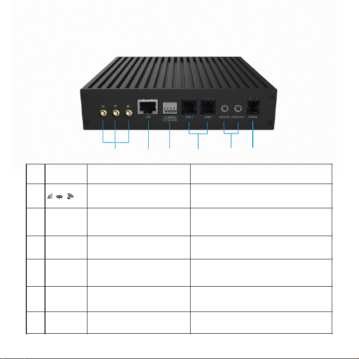
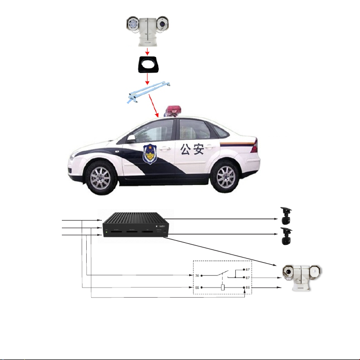
Kedacom KDM2412MX-0204A/TF User manual

智能车载记录仪
Quick Start Guide
快速使用指南
Mini 4G Vehicle NVR System


一、前言
感谢您购买我司产品,如对本公司产品有疑问或需要,请随时和我们联系。我们尽最大努力来保证
本手册信息的正确性,如因升级等原因发生信息修改,恕不另行通知。获取最新文档请联系产品供
应商。
二、安全说明
1
此内容(手册)的目的是确保用户正确使用本产品,以避免危险或财产损失。在使用产品之前,请
认真阅读此手册并妥善保存以备日后参考。如果用户因没有按照以下安全说明,致使设备不能正常
使用或损坏等情况,责任由用户承担。
电源要求
安装使用过程中,严格遵守使用地各项电气安全规定。
Ÿ
请使用满足安全电压要求的电源,在设备运行之前检查供电电源是否正确。
Ÿ
电源供电:DC 9~36V电源供电。
Ÿ
使用环境要求
请勿将设备安装在阳光直射的地方或发热源附近。
Ÿ
请保持设备水平放置,四周预留足够的空间,以利于空气流通、散热等。
Ÿ
请勿将设备置于潮湿、多尘、极热、极冷或强电磁干扰等场所。
Ÿ
请勿让任何液体流入设备,以免内部元件受损。
Ÿ
避免将产品暴露在非用户手册所示的工作环境下使用。
Ÿ
KDM2412MX-0204A/TF
KDM2412MX-0204A/TF-FD
KDM2412MX-0204A/TF-FS
KDM2412MX-0204A/TF-TD
KDM2412MX-0204A/TF-TS
本手册适用于以下型号:

线缆要求
安装线缆应与原车电缆走向一致,沿车辆原线缆安装布线,与原车辆电缆绑扎固定,做到布线整
Ÿ
齐、隐蔽,防止司机和乘客碰断。
无线网络天线以及定位天线需安装在信号较好的地方且注意防雷,同时确保不要有任何物体覆盖或
Ÿ
遮挡。
日常维护
请不要将较重的物品摆放在设备上,并防止设备从高处摔落或受强烈敲击。
Ÿ
如果设备工作不正常,请联系厂家或最近的服务中心。不要以任何方式随意拆卸或修改设备。
Ÿ
需要替换部件时,请事先与经销商联系,更换指定型号的部件,或与原部件具有相同特性的部件。
Ÿ
擅自使用其它部件进行替换,后果自负。
当运送设备时,请重新以出厂时的包装进行包装,或使用同等品质材料包装。
Ÿ
2
工作环境
工作电源
DC 9V~36V
温度
-35°C~+60°C
湿度
8%~90%(无凝结)
海拔
≤5000m

3
①②③
三、设备介绍
前面板
编号
部件名称
解释
说明
①
POW
电源指示灯
上电过程中电源指示灯常亮
②
SD CARD1/2
SD卡槽
2个SD卡插槽,支持各插入一张SD卡
③
SIM
SIM卡插槽
支持插入一张SIM卡,包括2G/3G/4G的中国移动
/联通/电信
④
Micro USB
Micro USB插口
支持USB接入PC调试
⑤
RESET
Reset复位按键
长按5秒,恢复出厂设置,设备重启
④⑤

4
后面板
编号
部件名称
解释
说明
⑥
4G、Wifi及GPS/BD天线接口
支持插入4G、Wifi以及GPS/BD 天线
⑦
LAN
LAN口
10M/100M自适应网口,可接车载云台摄
像机
⑧
ALARM IN
2路开关量告警
支持2路开关量告警输入
⑨
CAM-1/2
摄像机插口
2路FDCAM-100摄像机插口,各支持插入
1个FPD-LINK摄像机
⑩
AUDIO
IN/OUT
音频输入输出
音频3.5mm输入输出插口
⑪
POW IN
POW IN插口
电源输入插口,为主机供电
⑥⑦ ⑧ ⑨ ⑩ ⑪
4G

四、设备配置
电源接线介绍
在安装设备前,请先检查包装箱中的设备及组件,确保实际物品与装箱清单相符且物品无损坏现
象,若发现问题,请及时与供应商或客服联系。
当主机位于副驾驶座椅下方时,线从副驾驶脚垫下面出来连接主机,如下图所示。摄像机吸附于车
前挡风玻璃上。推荐用户安装两个摄像机,并将一个朝向车外,另一个则朝向车内。
1. 环境搭建
1) 设备安装
5
将左侧电源线插入设备电源插口中,图上所示右侧线缆为电源延长线。
CON
颜色
P2
信号
1
红
CUT
电源+
2
黑
CUT
电源-
3
绿
CUT
点火ACC

当主机位于后备箱时,连接车顶边缘下来的线,线缆走向如下图所示。安装支架两侧用螺丝固定。
6
如用户需要接入车载云台摄像机,请参见如下操作。
安装
1) 先将避震底座安装在车载支架上,然后再把摄像机安装在避震底座上。如果需要抬高摄像机的角
度,可以在避震底座和车载支架之间安装抬高底座。
2) 将安装好的车载支架固定安装在车顶,再固定好车载支架两侧的拉条。
【注意】
①安装过程中如果有警灯影响安装位置,可以将警灯向后移动,摄像机安装在警灯的前面。
②车载支架两侧拉条的固定长螺丝不可完全拧紧到底,要预留1cm左右的空隙,防止车辆在运动
颠簸中因拉力过大损坏车载支架拉条。

云台摄像机
安装车顶上
车载安装支架
连线
车电
9~36V
ACC
GND
VCC
继电器
VCC
ACC
GND
CAM-1
CAM-2
云台电源正极
云台电源GND
ETH
【说明】
① VCC为汽车电瓶电源正极;GND为电瓶的负极;ACC为汽车钥匙的点火检测。
② CAM1为KDM2412MX的FPDLINK摄像机的接口1;CAM2为KDM2412MX的FPDLINK摄像机
的接口2。
7

③ ETH为KDM2412MX的网口。
④ 图中的继电器为12V或24V车用继电器,依据车辆来选择。
⑤ 当云台电源的正极或GND的电流大于5A时,建议采用18AWG以上的线缆。
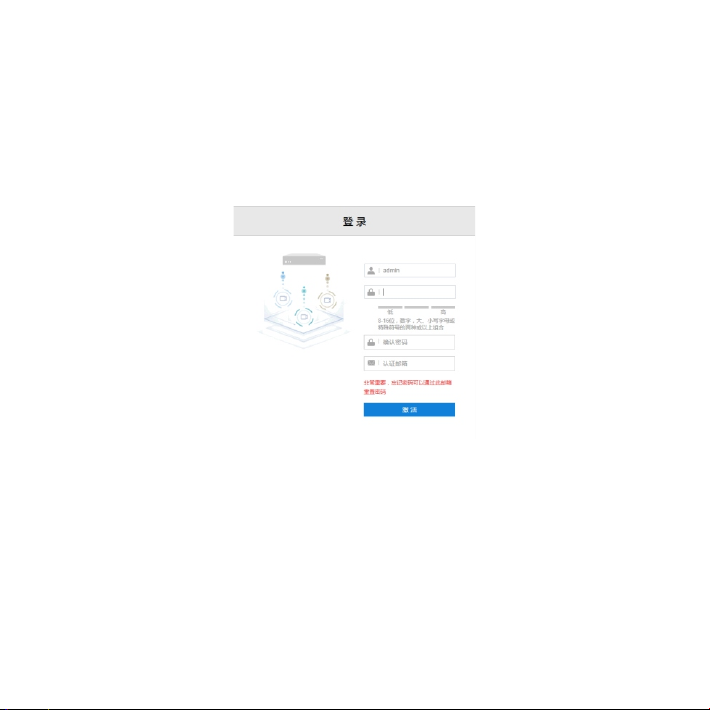
2) 设备激活后,进入浏览界面;(下次登录时,直接输入用户名及密码即可登录)
3) 进入配置> 网络配置>WIFI协议界面,勾选开启WIFI,将WLAN切换成AP热点,然后设置连接
密码。
接入平台
1) 进入配置>网络配置>接入平台>GB28181界面,勾选启用;
2) 填写入网ID,平台ID、地址、端口,用户名和密码以及视频源通道;
【说明】入网ID,平台ID、地址、端口以及用户名密码可在监控平台联网管理客户端上进行查看。
3) 点击保存按钮,设置生效。
2) 设备上电
设备安装好后,需再次进行检查线缆连接。检查无误后,设备上电。
2. WEB端配置
1) 设备上电后,通过网线连接到PC机。打开浏览器,输入默认IP192.168.0.99:8080,进入Web端,
设置admin用户密码,并填写邮箱(忘记密码可以通过此邮箱重置密码),激活设备;
8

连接视图库
1) 进入配置>网络配置>接入平台>视图库界面,勾选启用;
2) 选择视图库,填写设备ID以及对应视图库的IP地址、端口以及用户名密码;
3) 点击保存,设置生效。
9

3. PAD端配置
PAD端连接设备发出的无线热点,输入连接密码。
1) 第一次登录时,需在登录界面点击高级选项按钮,填写设备IP地址和端口;
2) 填写完成后,输入行车记录仪设备认证用户名以及密码(与WEB端激活时设置的用户名及密码
相同),视信通用户名及密码由用户注册视信通账号时自行设置。如不需要登录视信通账户,可点
击高级选项, 取消勾选登录视信通。
10
【注意】PAD端在登录前,需先进行WEB端的激活,否则PAD端无法登录。若设备进行ROM升级或
者恢复出厂等操作也可能需要重新激活。

本保修卡适用于您购买的本公司系列产品。
1.免费保修期一年(仅限中国大陆地区,中国大陆以外地区请参考英文说明)。
2.凡保修期内,由于本产品自身引起的故障,请与公司售后服务部联系。
3.保修时我们将使用您的保修卡信息,请认真填写。
4.以下情况,属于有偿保修范围:
-人为原因造成的设备故障
-因使用环境不符合本产品要求造成的故障
-因不可抗力造成的产品损坏
-无保修卡
-已过免费保修期
用户名称:
详细地址:
传真: 电话:
邮箱: 邮编:
产品名称:
产品型号:
购买日期:

1
During installing and using the device, please follow local electrical safety regulations strictly.
Ÿ
Please use power supply in the safe voltage range of our product. Make sure if the power supply is correct
Ÿ
before running the device.
Power supply: DC 9~36V.
Ÿ
Do not install the device at places where sunlight would shoot directly or near any heat source.
Ÿ
Please place the device horizontally and reserve enough space around it for air circulation and heat
Ÿ
dissipation.
Do not expose the device in damp, dusty, extremely hot or cold places or places with intense electromagnetic
Ÿ
radiation.
device to avoid damage to internal components.
ŸKeep the away from water or any liquid
Do not expose the device in the environment not defined in the Guide.
Ÿ
KDM2412MX-0204A/TF
KDM2412MX-0204A/TF-FD
KDM2412MX-0204A/TF-FS
KDM2412MX-0204A/TF-TD
KDM2412MX-0204A/TF-TS
I Preface
This guide applies to these models:
II Safety Instruction
Thank you for purchasing our product. If there are any questions, or requests, please do not hesitate to
contact us.
Every effort has been made to ensure the accuracy and validity of this Guide. Any update of this Guide is
subject to change without notice. For the latest document, please contact the dealer.
These instructions are intended to ensure that the user can use the product correctly to avoid danger or
property loss. Please read this Guide carefully before using the product, and keep it properly for future
reference. If the product cannot work normally or is damaged because the user does not follow the safety
instructions, we shall not assume any responsibility.
Power Supply
Working Environment

Wiring
The wires should go in accordance with that of the vehicle. Layout the wires along and bind with the vehicle
Ÿ
wires. Make sure the wires are neat and concealed and free from being broken by driver or passengers.
The WiFi and GPS antennas should be installed at a place with strong signal and be made lightningproof;
Ÿ
meanwhile, make sure no object is covering or shielding them.
Please do not put heavy objects on the device and prevent it from falling from a height or being strongly
Ÿ
knocked.
If the device does not work properly, please contact your dealer or the nearest service center. Never
Ÿ
disassemble or edit the device in any way.
ŸWhen it is necessary to replace a part, please contact your dealer in advance and replace the part with
specified model or part of the same features. We shall not assume any responsibility for problems caused by
unauthorized replacement.
device
ŸWhile shipping the , pack it in the factory packing or use materials with equivalent quality.
2
Working Environment
DC 9V 36V~
-35℃~+60℃
8%~90% (non-condensing)
no higher than 5000m
Voltage
Temp.
Humidity
Altitude
Daily Maintenance

3
①②③
III Device
Front Side
No.
Part
Name
Note
①
POW
power indicator
it is permanently on during powering on
②
SD CARD 1/2
SD card slot
2 SD card slots, each supports 1 SD card
③
SIM
SIM card slot
support 1 SIM card, including 2G/3G/4G signals
④
Micro USB
Micro USB slot
support USB accessing to PC for adjustment
⑤
RESET
Reset
long-press for 5s to reset to factory default and reboot
④⑤

4
Back Side
No.
Part
Name
Note
⑥
4G, Wifi and GPS antenna ports
support 4G, WiFi and GPS antennas
⑦
LAN
LAN port
10M/100M adaptive port, able to access to
vehicle PTZ camera
⑧
ALARM IN
2-channel alarms
support 2 channels of alarm input
⑨
CAM-1/2
Camera port
2 channels of FDCAM-100 camera port, each
supports 1 FPD-LINK camera
⑩
AUDIO
IN/OUT
Audio input/output
audio 3.5mm input/output port
⑪
POW IN
Power port
power supply port, electrifying the device
⑥⑦ ⑧ ⑨ ⑩ ⑪
4G

IV Configuration
Power Supply Connection
Before installation, please examine the device and accessories in the packing first to ensure the objects are
exactly as described on the packing list and are free from damages. If there's any question, please contact
your dealer or customer service person timely.
When the device is put at the bottom of the co-driver seat, the wire goes through the foot pad of co-driver seat
and connects to the device, as shown below. The camera is stuck on the front windshield. Suggest installing 2
cameras, one faces outward and another inward.
1. Setup
1) Installation
5
CON
1
2
3
Color
Red
Black
Green
P2
CUT
CUT
CUT
Igniter ACC
Signal
Power+
Power-
Insert the power cord on the left into the power port on the device. the wire on the right in the above picture is
the extension power cord.

6
When the device is put in the trunk, connect it to the wire going from from the margin of vehicle roof and
arrange it as the picture indicates. Fix the sides of the bracket with screws.
When user wants to connect it to the vehicle PTZ camera, follow the operations below.
Installation
1) Firstly, install the suspension base onto the vehicle bracket, then install the camera thereon. If you want to
raise the angle of the camera, you can install an elevated base between the suspension base and the vehicle
bracket.
2) Fix the mounted vehicle bracket onto the roof of the vehicle and then fix the bracing at the two sides of the
vehicle bracket.
[ATTN]
① During installation, if there is any police light hindering the mount position, move it backward and install the
camera before the police light.
② The fixing long screws on the bracing at two sides of the vehicle bracket cannot be screwed till the end.
About 1cm length of space should be reserved to prevent the vehicle bracket bracing from being damaged
by the large tension of the vehicle in bumpy movement.

7
Wiring
Vehicle
Power
9~36V
ACC
GND
VCC
Relay
VCC
ACC
GND
CAM-1
CAM-2
Positive Pole
Negative Pole
ETH
[Note]
(1) VCC is the positive pole of vehicle power supply; GND is the negative pole; ACC is the ignition detector of
vehicle key.
(2) CAM1 is the port 1 of KDM2412MX FPDLINK camera; CAM2 is the port 2 of KDM2412MX FPDLINK
camera.
This manual suits for next models
4
Table of contents
Other Kedacom DVR manuals