KEF T101 User manual
T Series Technologies Explained

2
KEF T Series Technologies Explained
1 INTRODUCTION
PART1-TSERIESCOMPONENTS
2 ULTRASLIMBASSDRIVER
3 LARGENEWVENTEDTWEETER
4 TOTALSYSTEMDESIGN
PARTII-TSERIESTECHNOLOGIES
5 VENTEDTWEETER
6 TWINLAYEREDMFDRIVER
7 TANGERINEWAVEGUIDE
8 SLIMSYSTEMDESIGN
9 WALL-MOUNTBASSEXTENSION
10 Z-FLEXSURROUND
CONTENTS

3
KEF T Series Technologies Explained
INTRODUCTION
With a flat screen TV, you want speakers to match. Really flat.
More importantly, you also want to fill the room with high
definition 3D sound that’s every bit as involving as what’s on
screen.
The best of home theatre
With KEF’s new T Series, you get exceptionally slim profile
speakers that generate all the intricacy, spaciousness and
dynamic range of a high end conventional design.
You’d expect no less from KEF.
With some of the finest speakers in the world to our credit,
ours is a 50-year success story of innovation that includes
unrivalled experience of home theatre: our multi-award winning
systems have for years been the standard by which others are
judged.
No wonder even the most demanding listeners love the new T
Series the first time they hear it – and when you discover the
unique technologies crammed into each slender enclosure, you
understand why…
4
KEF T Series Technologies Explained
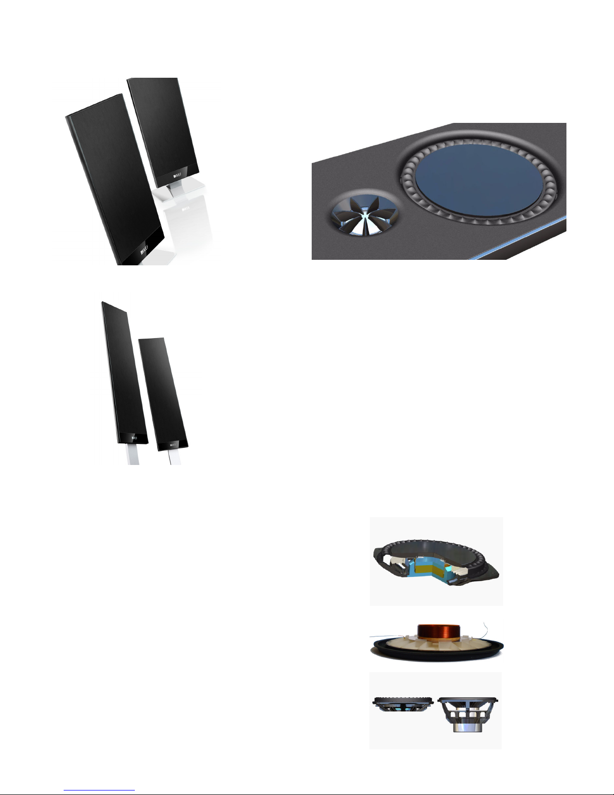
• Cut-away CAD rendering of the new T-Series midrange driver.
• Prototype parts show the twin layered structure.
• Comparison of new T-Series driver (left) with a conventional driver of the same cone
diameter (right).
The new T Series is aimed at delivering true hi- performance in
ultra-shallow speaker enclosures to meet the demand for speaker
systems to physically match the new generation of OLED and
LED TVs.
PART1-TSERIESCOMPONENTS
ULTRASLIMBASSDRIVER
At the heart of the T101 and T301 satellites is the new Twin Layered MF
Driver. This revolutionary low prole drive unit is incredibly slim (only
27mm deep). However, it delivers the performance of a drive unit several
times its depth.
Twin Layered Radiating Diaphragm
The T-Series uses a Twin Layered MF Driver (patent pending). This is
comprised of a moulded radiating diaphragm with integral stiffening ribs
running radially and circumferentially. A thin layer of high modulus
material on the rear of the ribs provides additional stiffness. This structure
ensures the diaphragm moves pistonically within its working frequency
band, whilst occupying a depth of only 5mm. This technology has been
developed and optimised using nite element analysis.
Z-Flex Surround
The T-Series Midrange Driver features a Z-Flex Surround. This
• The T101 is the smallest satellite in the T-series range housing a 25mm (1 inch) tweeter and
a 120mm (4 inch) midrange driver
• The T301 is the largest satellite in the T-series range housing a 25mm (1 inch) tweeter
between two 120mm (4 inch) midrange drivers
revolutionary new design minimises mass-loading on the edge of the
diaphragm helping maintain pistonic motion up to a high frequency. Its
carefully designed undulations and supporting block prevent resonances
whilst allowing simple motion such as the diaphragm moving forwards
and backwards. The relatively at and smooth form surface of the Z-Flex
Surround minimises colouration to sound from the Tweeter. Finite
element analysis was used heavily in the development of this new
surround.
Concentric Suspension
Conventional midrange drivers have a cone, voice coil in a magnetic gap,
and a suspension attached between them around the voice coil former.
There must be enough space around the suspension to prevent it
colliding with the other parts as the driver moves backwards and
forwards. This sequential arrangement of the three parts plus clearances
restricts the minimum depth of the driver. For many loudspeakers this is
unimportant, but the T-Series Slim System Design demands a slimmer
driver.
The T-Series Midrange Driver suspension has been designed for low build
height. Its inner edge has a larger diameter than the former, so it sits
concentrically around the voice coil. The main ‘rolls’ of the suspension are
aligned with its outer mounting position on the driver chassis. The inner
edge protrudes up to attach to moulded tabs on the rear of the
diaphragm ribs. This protrusion is sometimes known as a ‘cup’, in a such a
suspension the ‘cup’ allows for the difference in height of the mounting
positions and prevents the suspension hitting the rear of the diaphragm.
The cup is reinforced with a metal loop (patent pending). This prevents
excessive bending as the diaphragm moves backwards which keeps the
suspension stiffness symmetrical and high enough to limit motion. This
minimises distortion and increases the power handling of the midrange
drive unit.

5
KEF T Series Technologies Explained
TOTALSYSTEMDESIGN
Cabinet
The cabinet structure for the T-series incorporates a number of
clever features which help to retain the minimum build height.
The speaker is easy to install and flexible in the way it can be
positioned. As with all KEF speakers, special care has been taken
to control cabinet resonances.
Minimum build height
The terminals have been fully integrated into the cabinet to
avoid adding to the depth of the speaker. The T-series also
features zero build height wall mounting connections. Some TVs
and speakers advertise that they are slim design, but the wall
brackets can drastically add to the depth when wall mounted.
The T-series wall brackets only add 2.5mm to the product depth
when wall mounted.
• CAD cutaway showing the new T-Series midrange driver mounted into the T-Series
cabinet.
Subwoofer
The T2 is a slim and sleek subwoofer ideally designed for use
with the T-series. The strong and inert enclosure houses a
250mm (10in.) bass drive unit in a closed box configuration. This
closed box configuration delivers tight and accurate bass ideal
for music. The variable EQ allows you to tailor the bass output
to delivery truly earth shaking bass for the ultimate home
theatre experience. The T2 features an ultra-reliable, high
efficiency 250W Class-D amplifier, which can play very loud and
very clean - all day long if necessary.
The subwoofer is normally one of the largest speakers in a
home theatre system and as such we have designed the T2 to
be as slim as possible, allowing it to be positioned close to a wall
or in the corner with no reduction in its performance. This
allows you to maintain a clean, clutter free look whilst still
delivering a level of performance that you would expect from a
much larger subwoofer. The T2 also uses SmartBass™ “connect
and go” technology for simplicity of set up. Our engineers have
carefully designed the T2 to be as easy and practical as possible;
just connect it to the mains and your AV receiver to be assured
of optimum performance without the hassle of “tweaking”.
Flexible stands
The desk stand for the centre speakers allow you to have the
centre speaker positioned vertically or tilted back by 5 degrees.
This allows the speaker to be directed towards the listener,
increasing the intelligibility of the critical centre channel.
Fully braced structure
Cabinet mechanics is an important part of the system design
and special care has been taken to ensure these new cabinets
are acoustically inert. This is critical for maintaining the clean
midrange produced by the new drive units. The drive units and
cabinets have been designed together in such a way that the
drive units brace the cabinets to stop any unwanted cabinet
resonances that could colour the sound.
LARGENEWVENTEDTWEETER
In recent years KEF has made great progress in tweeter technology and
for the new T-Series we have been able to use some of the technology
we use in our high end products. The diameter of the tweeter has been
increased to 25mm instead of the 19mm that is more usual on products
of this kind. The 25mm size has the ideal compromise between high
frequency extension and output capability which is why we use 25mm
tweeters on our agship Muon and Reference Series models.
Despite the very shallow depth of the loudspeaker we have been able to
incorporate a venting system into the rear of the tweeter magnet system
similar to that found in the KEF Reference Series.
Another distinctive feature of the tweeter is the Tangerine Waveguide
which covers the dome which increases the sensitivity and dispersion at
the very top end. We have also paid a lot of attention to the lower end
of the tweeter to ensure that we have a low resonance which allows us
to use the tweeter over a wider bandwidth and to use a simpler
crossover design.
Many hours of careful analysis and design have resulted in us being able
to put technologies into this design which in previous years would only
have been found in the very highest-end loudspeakers.
• Detail of tweeter showing Tangerine
Waveguide and rear venting.
• T-series Vented Tweeter and Tangerine
Waveguide.
6
KEF T Series Technologies Explained
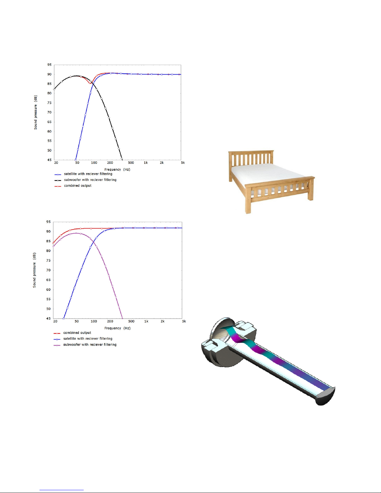
• A satellite designed for maximum bass when used on its own does not integrate well with a
subwoofer.
• A satellite designed specically for use with a subwoofer integrates well.
All of this means that the T2 is an ideal subwoofer if you want a
‘no compromises’ performer without the hassle of a large box
that just doesn’t look right in your room; whether you are
listening to your favourite music or watching the latest
Hollywood blockbuster.
PARTII-
TSERIESTECHNOLOGIES
VENTEDTWEETER
The T-Series has a Vented Tweeter. This increases the amount of air
enclosed behind the dome to reduce distortion of the sound.
An Analogy
Imagine two mattresses made from the same type of foam, one
thick and one thin. Most people would find the thick mattress
more comfortable. This is because their weight on the thin
mattress compresses it to the point that they can feel the hard
bed slats beneath. The extra material of the thick mattress means
it is not compressed fully and thus still feels soft and springy.
Air Behind the Tweeter Dome
The dome of a tweeter vibrates the air around it, in front of the
dome this vibration is propagated away as sound, to the rear is
an enclosed pocket of air. The dome pushing on the enclosed air
experiences something similar to the person on the mattress. If
the enclosure is too small the air undergoes large compressions
and expansions. It will behave in a non-linear manner and cause
distortion. This can be compared to the discomfort of laying on
the thin mattress. In a larger enclosure the compressions and
expansions are relatively small. The air in this case will act as a
spring and the sound we hear will have much lower distortion.
The image above shows the behaviour of the tweeter vent. Rear
radiation from the dome travels down the duct and is gently
absorbed in the acoustic damping material.
7
KEF T Series Technologies Explained
References
1. M. Dodd and J. Oclee-Brown, “A New Methodology for the Acoustic Design of Compression
Driver Phase Plugs with Concentric Annular Channels,” presented at The 123rd Convention
of the AES, preprint 7258, Oct 2007.
2. M. Dodd and J. Oclee-Brown, “A New Methodology for the Acoustic Design of Compression
Driver Phase Plugs with Radial Channels,” presented at The 125th Convention of the AES,
preprint 7532, Oct 2008.
TWINLAYEREDMFDRIVER
The T-Series Midrange Driver features a twin layered radiating
diaphragm. This technology (patent pending) allows the driver to
be slim and flat whilst still maintaining pistonic motion up to a
high frequency. The design has been optimised by finite element
analysis.
Slim Driver
The Slim System Design means the the Midrange Driver can be
only 27mm deep. The space required for the magnet assembly,
and that required to allow 4mm of diaphragm excursion
forwards and backwards, leaves only 5mm of depth for the
diaphragm. A simple flat diaphragm geometry has very little
inherent stiffness. Such a flat diaphragm would have structural
bending resonances at low frequencies, which would affect the
magnitude and directivity of the radiated sound field within the
working range of the driver. Over the midrange driver’s 95mm
diameter a conventional cone or dome geometry of this depth
would have very little curvature and thus again little inherent
stiffness. The twin layered diaphragm design has high stiffness in
spite of its restricted depth. There is no diaphragm resonance
below 2kHz which is its operating bandwidth.
Perfect Baffle
Discontinuities in the loudspeaker baffle cause reflections and
resonances of higher frequency sound waves. A deep cone
midrange driver can therefore colour the sound of a nearby
tweeter. The flat fronted T-Series Midrange Driver with smooth
surround has minimal effect on the tweeter. This is a step
towards creating the Perfect Baffle as seen in the KEF Concept
Blade.
Twin Layered Structure
The radiating diaphragm is a thin walled moulding. The material
is chosen to provide relatively high stiffness and damping with
the ability to be moulded into thin sections (down to 0.3mm).
Ribs extend perpendicular to the rear of the surface. These are
positioned both radially and circumferentially. The radial ribs
significantly stiffen the diaphragm to raise the frequency of its
fundamental (circularly symmetrical) resonance. The circular ribs
are located for attaching the voice coil former and suspension
and brace the diaphragm structure.The twin layered structure
has a thin layer of high elastic modulus material on the back of
the ribs. This increases the diaphragm stiffness further to push
the fundamental resonance above the working frequency
bandwidth of the midrange driver.
The technology has been developed using finite element analysis
(FEA) computer modelling. This allows very fine optimisation of
the design geometry and materials to produce a very high
performance loudspeaker driver.
Ventilation
Gaps in the circumferential ribs and holes in the rear layer allow
air flow through the structure. The straight radial ribs provide
uninterrupted air channels. This prevents high air pressure
fluctuations within the voice coil under the vibrating diaphragm.
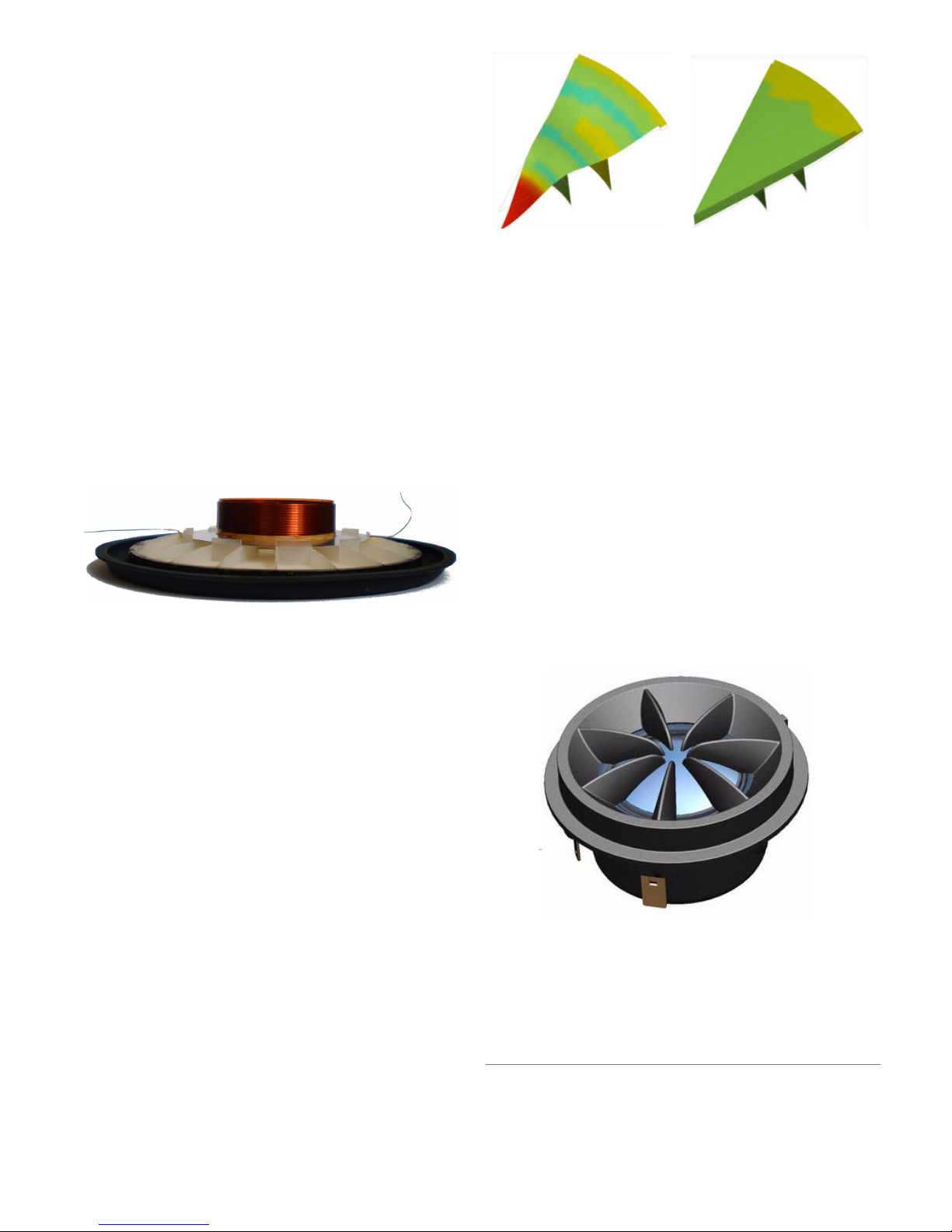
TANGERINEWAVEGUIDE
The Tangerine Waveguide is a patented KEF Technology which is
now used in a number of products throughout the range. The
technology was developed from research work into compression
drivers which are used in high power systems for concerts.[1]
Compression drivers are very susceptible to acoustic resonances
which occur in front of the tweeter dome. Whilst looking into
the behaviour of compression drivers in detail, it was realised
that the source of these acoustic resonances is also present in a
normal direct radiating tweeter. The Tangerine Waveguide is
designed to compensate for these problems thereby improving
the coupling between the tweeter dome and the air.[2]
• A at diaphragm using conventional
technology resonates severely.
• A at diaphragm using new twin layered
technology behaves almost pistonically.

8
KEF T Series Technologies Explained
WALL-MOUNTBASSEXTENSION
The sound of a loudspeaker will vary depending on where it is
positioned relative to the walls of a room. Generally,
loudspeakers sound best when they are positioned in “free
space”, for example, on a stand, more than 0.5m from any walls.
This is what produces a natural sound, in the same way that the
sound of someone speaking or playing a musical instrument will
be best when they are well away from the walls and corners of
the room.
When a loudspeaker is positioned “on-wall” the sound changes
in a relatively predictable way: the upper bass is enhanced and a
dip appears in the midrange – this is what we instinctively
recognize as the “wall effect”. However, if we know that a
particular speaker will generally be positioned “on-wall” we can
correct for these effects and ensure that the speaker will sound
natural in that position.
SLIMSYSTEMDESIGN
Satellite speakers designed to match the current generation of
plasma and LCD flat panel TVs typically have a depth of around
100mm (4 in.). The KEF KHT6000, for example, is one of the
shallowest at a basic speaker depth of 85mm. However, the
latest LED and OLED flat TVs are significantly shallower than
this and there is a definite requirement for speaker systems of
similar depth proportions but with true hi-fi performance.
Extremely slim system design
The key to reducing the depth of the T series satellites is a new
ultra-shallow midrange drive unit which has a total depth of
only 27mm (compared to 70mm for the KHT3000 Uni-Q from
which it is derived). This is achieved without any reduction in
cone area, so the acoustic performance of a true 4.5 inch unit is
maintained. This new bass/midrange unit has allowed a total
enclosure depth of only 37mm including the wall bracket.
Enclosures of such shallow dimensions require careful
mechanical design to ensure the internal volume is fully utilized
by the drive units with minimal acoustic losses and that panel
resonances are kept to insignificant levels by suitable bracing. In
addition, the packaging of the internal crossover network,
acoustic damping materials, internal cabling and connections all
require special attention so that the key acoustic parameters
are not compromised and ergonomics are straightforward and
logical.
• The new T Series is designed to look right
at home next to the latest thin screens.
• Simulation showing the bass response boost wall effect.
• A comparison of a prototype satellite
alongside the prototype HTS3001 satellite
speaker.
Selecta-Mount
Because the T Series satellites are designed to match the new
generation of super slim TVs and will generally be mounted
“on-wall” using the supplied bracket or positioned very close to
the wall on the desk stand, they have been specifically balanced
for the “on-wall” location. However, for those occasions when
they are used on the floor stand - when they will be a significant
distance from the nearest wall – the KEF Selecta-mount system
automatically adjusts the balance for an “off-wall” location. This is
accomplished by a clever connection arrangement in the stands
which introduces an extra filter section ahead of the speaker’s
crossover network to switch the speaker into its “free-space”
balance.
• The oor stand neatly connects to the loudspeaker and automatically adjusts the satellite for
optimum freespace performance.
• Within the stand a small electrical circuit makes the response adjustments, terminals are
located at the base for easy connection.
9
KEF T Series Technologies Explained
Z-FLEXSURROUND
An important feature of the T Series Midrange Driver is the new
Z-Flex Surround. The surround is a critical component of any
bass/midrange driver. The designer must carefully choose the
material and shape so as to avoid irregularities in the midband
response due to resonance in the moving parts whilst at the
same time allowing sufficient excursion of the cone in order to
reproduce bass frequencies. Most modern drivers use a half-roll
design typically moulded from butyl rubber. The half-roll design
can often perform well if carefully designed, however, KEF’s
computer modelling techniques have allowed us to investigate
some more adventurous possibilities. The Z-Flex surround is the
result.
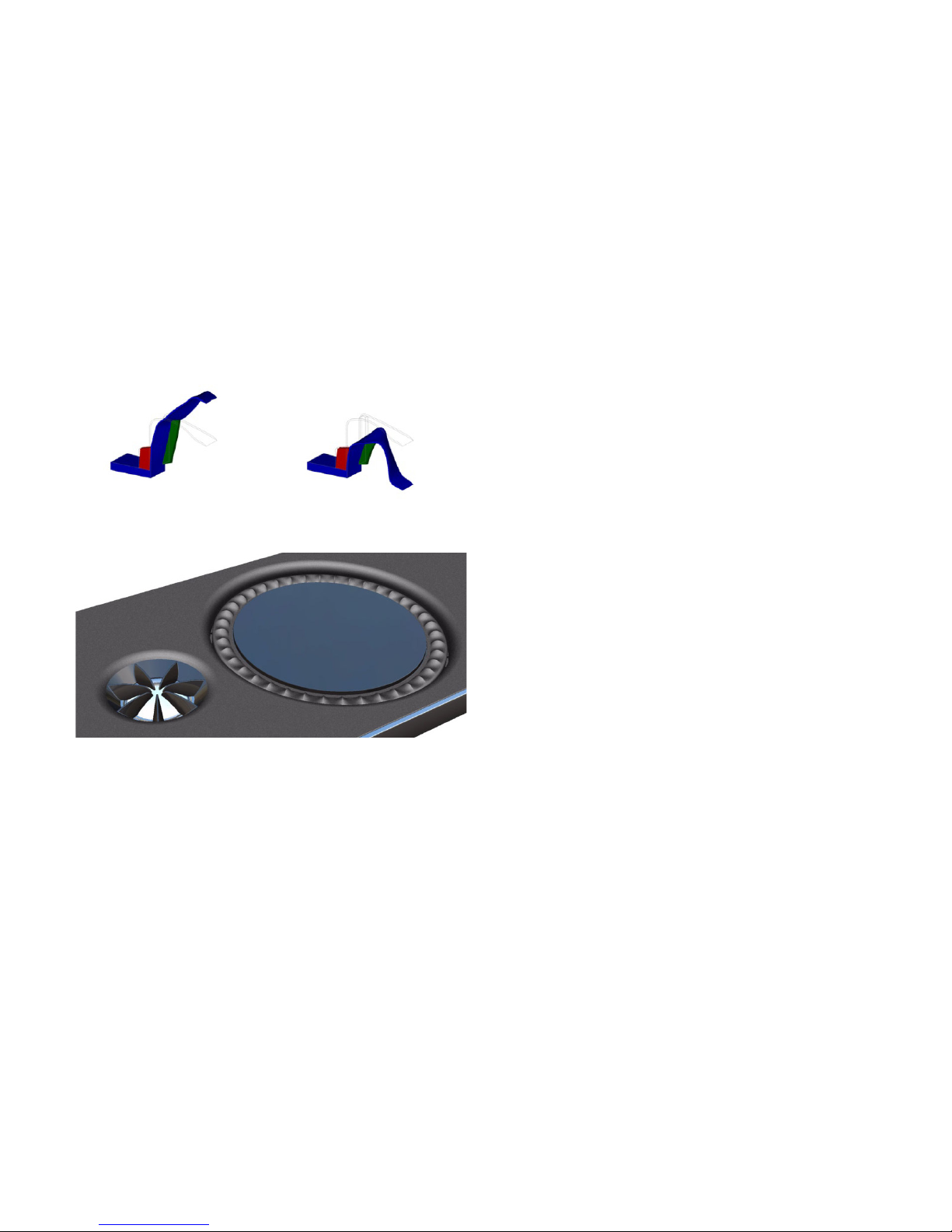
The images below show how the Z-Flex surround changes
shape when the cone moves back and forth. This is quite unlike
the motion that is normally seen with a conventional half-roll
design.
Design Features
Unlike a conventional surround, the Z-Flex allows very fine
control over the surround behaviour. There are three main
features which are critical to the performance:
• The membrane sections which form the air seal
• The supporting blocks attached to the membrane
• The undulations on the front surface of the membrane
The membrane section is present to form an air seal, the size of
the front and side walls are chosen to allow the driver to move
to its full extent whilst minimising diaphragm edge mass loading.
The supporting blocks and the front surface undulations are
present to control the behaviour of the surround in the mid
band. The positions, shapes and sizes of these two features fine
tune both the mechanical impedance which the surround
presents to the cone edge and also the dynamic behaviour of
the surround itself. In essence, the Z-Flex will readily allow
simple deformations, such as those occurring at low frequencies
when the cone is moving some distance back and forward, but
greatly resist complex deformations such as those which can
cause problems in the mid-band. Conventional problems, for
• FEA model showing the Z-Flex surround
deformation as the cone moves forward.
• FEA model showing the Z-Flex surround
deformation as the cone moves backward.
example the surround termination dip, can then be completely
avoided by fine tuning the design.
Minimised Edge Mass Loading
A major benefit of the Z-Flex approach is that, for a given cone
excursion, less of the surround moves and hence the surround
contributes a much lower effective mass to the cone edge. The
effective mass decreases with increasing driving frequency. This is
important in minimising mass-loading of the edge of the
diaphragm which would lower the frequency of the diaphragm
bending resonances. The Z-flex surround therefore works in
conjunction with the Twin Layered MF Driver technology to
achieve pistoning diaphragm motion throughout the working
band.
Perfect Baffle
Discontinuities in the surface of a loudspeaker’s baffle cause
reflections of the higher frequency sound waves. Features such
as a large roll surround can therefore colour the sound of the
tweeter. The smooth and low profile Z-Flex Surround, in
conjunction with the flat fronted diaphragm of the Twin Layered
MF Driver, have only a minimal effect on the acoustic waves
being radiated by the tweeter. Perfect Baffle was a technology
first introduced for the KEF Concept Blade Loudspeaker.

10
KEF T Series Technologies Explained
www.kef.com
United Kingdom
GP Acoustics (UK) Limited
Eccleston Road, Tovil, Maidstone,
Kent, ME15 6QP U.K.
Telephone: + 44 (0) 1622 672261
Fax: + 44 (0) 1622 750653
Email: [email protected]
China
GP Acoustics (China) Limited
Unit 4910, Diwang Commercial Centre,
Shenzhen, China 518008.
Telephone: +86 (755) 8246 0746
Fax: +86 (755) 8246 0125
Email: [email protected]
Europe (EMEA)
GP Acoustics GmbH
Am Brambusch 22, 44536, Lünen,
Deutschland.
Telephone: +49 (0) 231 9860-320
Fax: +49 (0) 231 9860-330
Email: [email protected]
France
GP Acoustics (France) SAS
39 Rue des Granges Galand - BP60414,
37554 Saint Avertin CEDEX, France.
Telephone: +33 (0) 2 47 80 49 01
Fax: +33 (0) 2 47 27 89 64
Email: [email protected]
Hong Kong
GP Acoustics (HK) Limited
6F, Gold Peak Building,
30 Kwai Wing Road, Kwai Chung,
N.T., Hong Kong.
Telephone: +852 2410 8188
Fax: +852 2401 0754
Email: [email protected]
Japan
KEF JAPAN, 1-11-17, Honcho, Koganei-city,
Tokyo, Japan. 184-0004.
Telephone: +81 (0) 42-388-2030
E-mail: [email protected]
USA
GP Acoustics (US) Inc.,
10 Timber Lane, Marlboro,
New Jersey 07746 U.S.A.
Telephone: +1 (732) 683 2356
Fax: +1 (732) 683 2358
Email: [email protected]
KEF is a registered trademarks. KEF technologies are
protected by worldwide patents. All text and image
copyrights reserved. KEF reserves the right, in line
with continuing research and development, to amend
or change specications. E&OE.
This manual suits for next models
1
Table of contents
Other KEF Speakers manuals


