OPERATION MANUAL
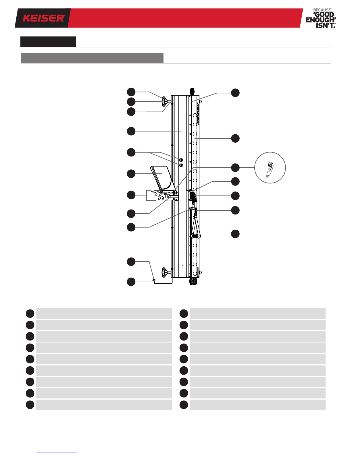
PERFORMANCE TRAINER 04
It is the sole responsibility of the purchaser of Keiser Corporation
equipment to instruct all individuals, whether they are the end
user or supervising personnel, on proper usage of the equipment.
Keiser Corporation recommends that all users of its equipment
be informed of the following information prior to use.
1. Read these instructions.
2. Heed all warnings.
3. Follow all instructions.
4. Consult your physician before beginning any exercise program.
5. The Performance Trainer is intended for use in training areas
of organizations where access and control is specically
regulated by a person responsible for determining the
suitability of use and maintenance.
6. Use of this Performance Trainer for any purpose not explicitly
specied by the manufacturer in this manual is prohibited.
7. Wear proper exercise clothing and shoes for exercise. Avoid
wearing loose clothing that might catch on any moving parts.
Tie long hair back.
8. The Performance Trainer is not a toy. Children should not
play with the Performance Trainer. Children under 14 years
old should not use the Performance Trainer. Keep children
and pets clear from the Performance Trainer at all times,
especially while in use. Cleaning and user maintenance should
not be performed by children.
9. Children age 14 to 17 years should not use the Performance
Trainer without constant supervision by a spotter/supervisor.
Persons with mental disabilities, reduced physical, mental,
or sensory capabilities, or lack of experience or knowledge
should not use the Performance Trainer without constant
supervision by a spotter/supervisor.
10. Proper warm up is required to help prevent serious injury.
This Performance Trainer should only be used with proper
instructions. Always maintain good form and control during
exercise. If you feel pain or are unable to maintain good form,
stop immediately. Failure to follow these instructions could
result in serious injury.
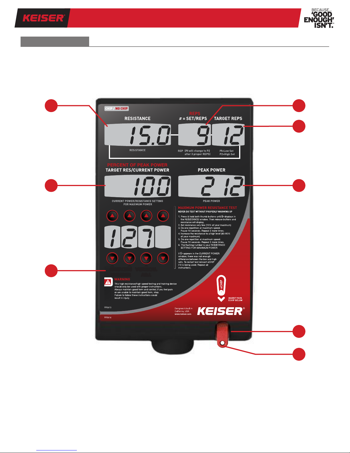
11. Never perform Power Test without proper warm up. This high
resistance/high speed test should only be performed with
proper instruction (see page 12 “Power Test” for complete
instruction). Always maintain good form and control during
the test. If you feel pain or are unable to maintain good form,
stop immediately. Failure to follow these instructions could
result in serious injury.
12. Use only Keiser accessories with your Performance Trainer
to help avoid the risk of serious injury or property damage.
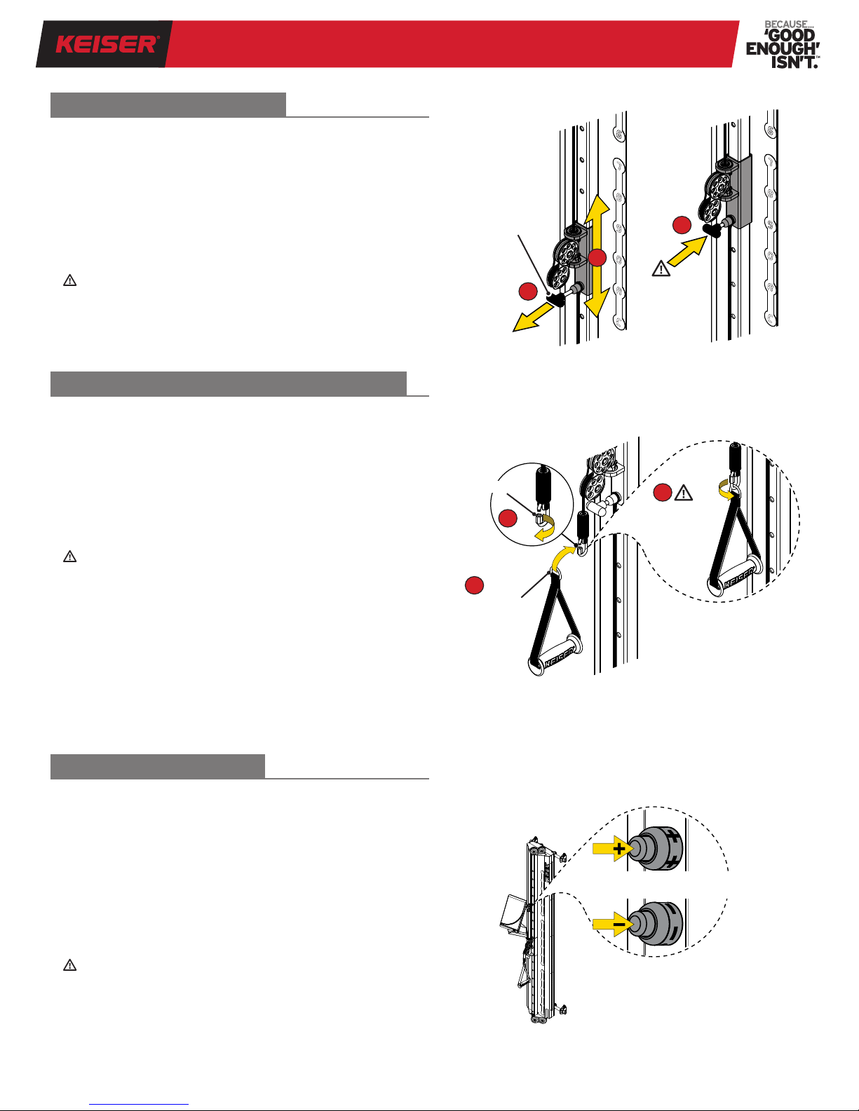
13. Ensure the Cable Link is closed before use of a Cable
Accessory.
14. Sudden release of a Cable Accessory will cause it to snap back
uncontrollably and could result in serious injury or property
damage. Maintain a rm grasp of a Cable Accessory during
exercise. Ensure hook and loop type accessories are fastened
rmly before exercise. Carefully return the Cable Accessory
to the start position before releasing.
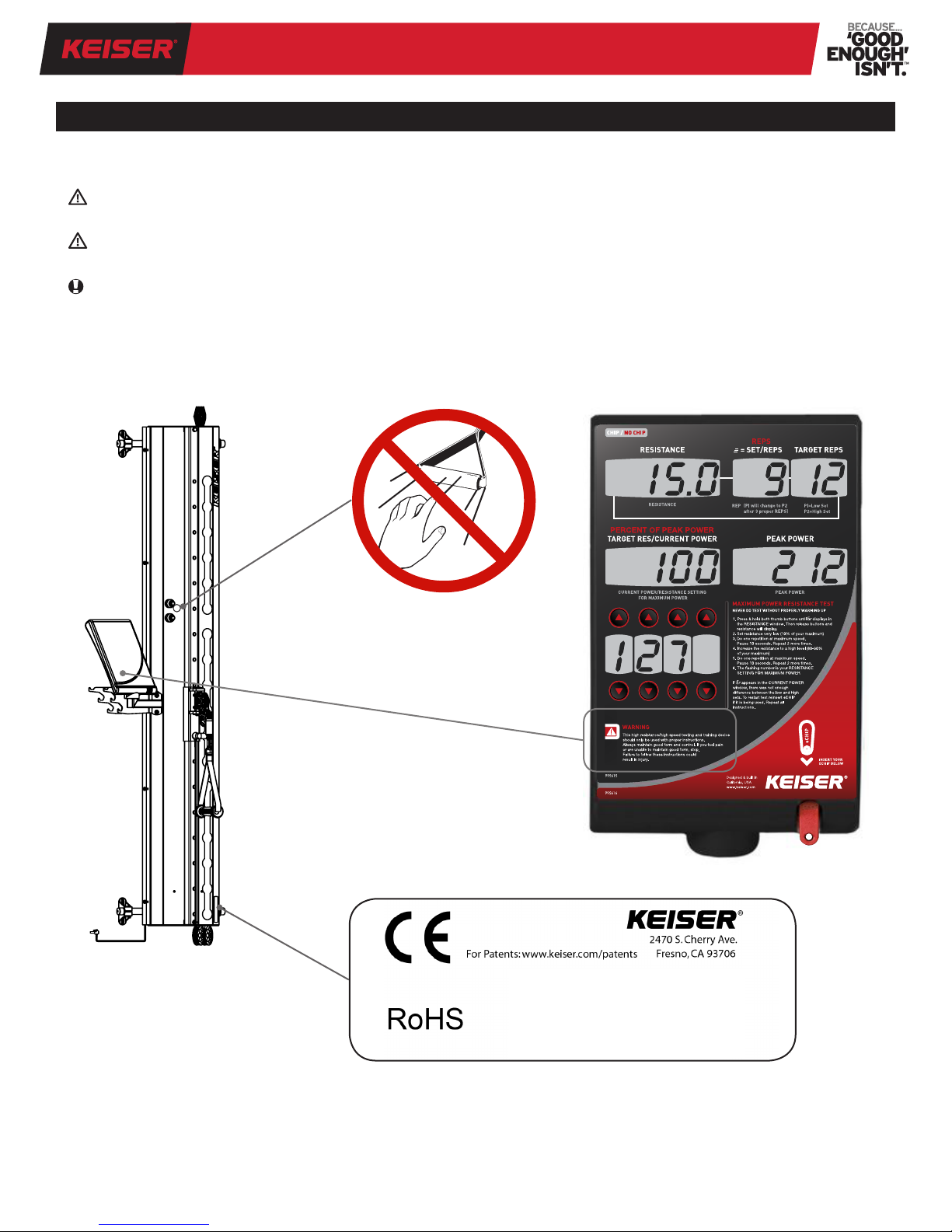
IMPORTANT SAFETY INFORMATION
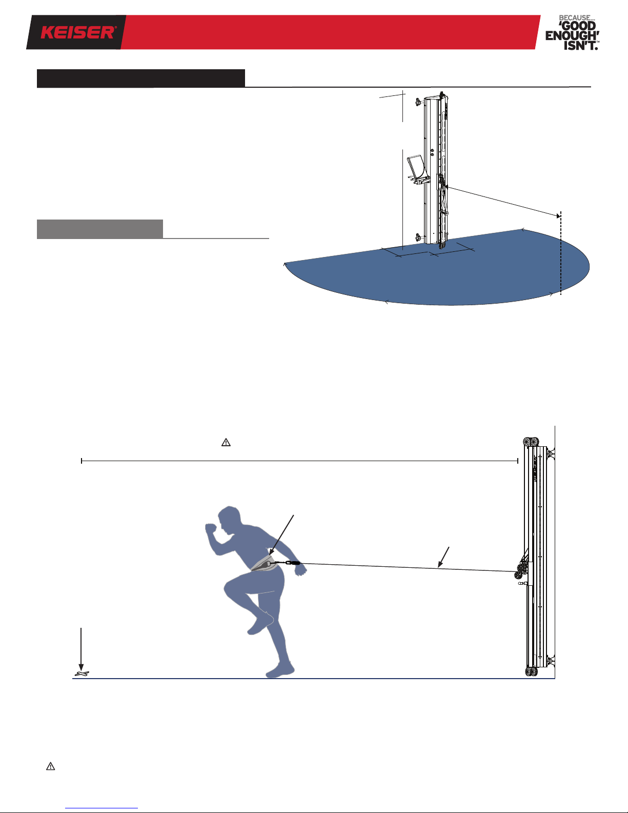
15. Do not pull Cable beyond maximum Cable length of 96 inches
(2,438 mm). Failure to follow this direction will cause the
cable to hit a hard stop and will create a sudden dynamic load
that may result in serious injury or equipment and property
damage.
16. Never make adjustments to the resistance during exercise
as this may cause muscle strain. Always return the Handle/
Cable to the start position prior to making any adjustments
to help prevent serious injury.
17. Ensure that the Adjustment Plunger is fully engaged into the
desired position hole before use. There should be no up/down
movement of the Vertical Adjustment once it is set in position.
18. The highest level of safety can only be ensured if the equipment
is regularly inspected for damage and wear. Always check
equipment is securely fastened to the Wall Mount Tubes and
wall before use (no tilt, lean, or any other movement of the
unit should be detected during use). Immediately replace
damaged, worn, or broken parts. Do not use the Performance
Trainer until all repairs have been completed and tested by
a Keiser-certied technician.
19. Use only replacement parts supplied/recommended by Keiser
Corporation. Attempting to repair or replace any damaged,
worn, or broken parts on your own is not recommended. A
Keiser-certied technician should be consulted.
20. The use of any exercise equipment, including, without
limitation, Keiser’s strength training equipment in which
resistance can be changed at any time during the repetition,
without proper instruction and supervision violates the terms
of the agreement for purchase of such products. The ability
to add resistance anytime during a repetition, including,
without limitation, the ability to do a heavy negative may
be dangerous, especially for anyone that does not recognize
or respect the potential danger.
21. Users, agents, or anyone directing the use of the Performance
Trainer shall determine the suitability of the Performance
Trainer for its intended use, and said parties are specically
put on notice that they shall assume all risk and liability in
connection herewith.
22. The Performance Trainer is intended for use in commercial
training centers. If the Performance Trainer is used in a
residential setting, special precautions should be taken.
To ensure your safety and to help prevent damage to the
Performance Trainer, read all instructions before operating.
Seek professional installation by qualied personnel as
dictated by authority having jurisdiction.
23. If you do not understand these instructions or have doubts
about the safety of the installation, assembly, or use of this
product, contact Keiser Customer Support:
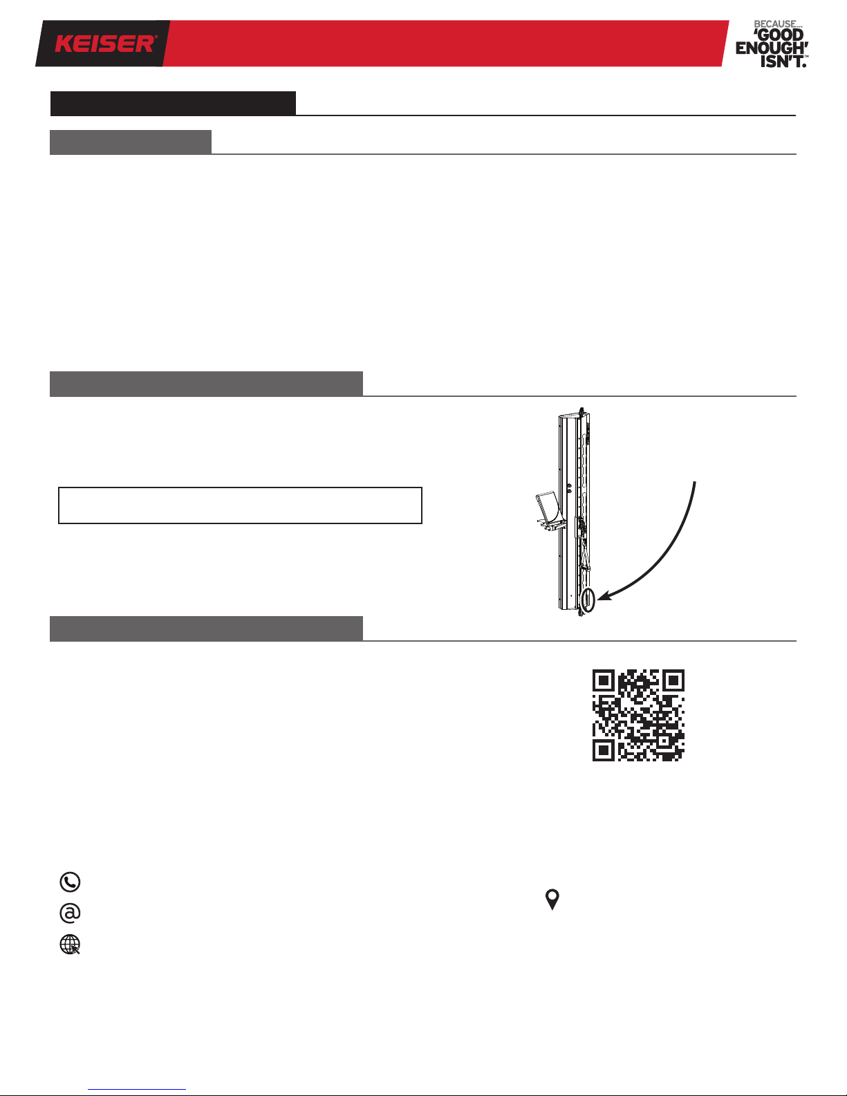
1 559 256 8000
service@keiser.com
keiser.com/support