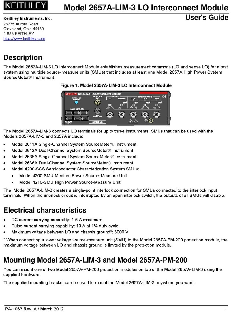
2.5 OPERATION CONSIDERATIONS
Signal Level-The maximum signal levels that the Model 7053 high current
card operates at are 300V maximum, 6A or lOOVA peak iresistive load only).
The contact life of the relays at maximum signal levels is greeter than lo5
operations. NOTE
Maximum signal specifications apply to scanner output as well
as inputs. For example, multiple channel closures cannot put
more than 5A onto the output.
WARNING
When switching signals greater than 30V rms or 42.4V
rms peak take care to prevent contact with live circuits
which could cause electrical shock resulting in injury or
death.
Cables-Sheilded cables should be used with the Model 7053 high current
card and when switching above 5OV or high current. The shield should be
connected to circuit guard. This helps prevent excessive radiation from the
cables from interfering with any equipment. The cable rating must exceed the
maximum allowable signal levels as defined in the specifications.
External Considerations-The Model 7053 is specified for a resistive load,
however, external circuit capacitances and inductances can cause excessive
currents and voltages across the relay contacts. The currents and voltages
must be limited to within the maximum allowable signal levels.
1. Capacitance-Charged capacitances in the circuit can cause excessive
currents (surge currents) to flow through the relay contacts if the source i8
shorted out or the output is switched to capacitive loads. This excessive
current can weld the relay contacts together. Therefore, use series resistors,
where needed, to limit the maximum current that can flow to within contact
ratings. The maximum signal levels are stated in the specifications.
2. Inductance-The inductance of cables can produce high voltage and arc-
ing across relay contacts when switching. The peak transients must be
limited to within the maximum signal levels as defined in the specifications.
2.6 MODEL 7053 MODIFICATION
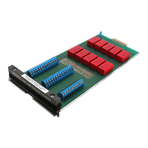
Unselected inputs on the Model 7053 high current scanner card, are shorted
(HI to LO) via installed jumpers (WlOl-WllO). If isolation is required between
channel LO and channel HI. the Model 7053 can be modified to disconnect
channel LO from channel HI when a relay is off lopenl. The modification in-
volves removing a jumper wire for the channel that is to be modified. For ex-
ample, remove jumper WlOl to disconnect channel l’s HI terminal from chan-
nel l’s LO terminal. Refer to the component layout (Figure 6) for jumper lxx-
tion.
It is recommended to remove the jumpers by cutting them with a pair of wire
CUttOE.
2.7 SWITCH TERMINOLOGY
Throughout this manual the terminology Form C is used. The term Form C is
used in switch terminology and is described 88 follows:
St
Artisan Technology Group - Quality Instrumentation ... Guaranteed | (888) 88-SOURCE | www.artisantg.com
