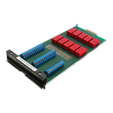
Keithley 7065 User manual

www.keithley.com
A GREATER MEASURE OF CONFIDENCE
Model 7065 Hall Effect Card
Instruction Manual
7065-901-01 Rev. C / July 2009

A G R E A T E R M E A S U R E O F C O N F I D E N C E
Keithley Instruments, Inc.
Corporate Headquarters • 28775 Aurora Road • Cleveland, Ohio 44139
440-248-0400 • Fax: 440-248-6168 • 1-888-KEITHLEY (1-888-534-8453) • www.keithley.com
3/07
WARRANTY
Keithley Instruments, Inc. warrants this product to be free from defects in material and workmanship for a period of
one (1) year from date of shipment.
Keithley Instruments, Inc. warrants the following items for 90 days from the date of shipment: probes, cables,
software, rechargeable batteries, diskettes, and documentation.
During the warranty period, Keithley Instruments will, at its option, either repair or replace any product that proves
to be defective.
To exercise this warranty, write or call your local Keithley Instruments representative, or contact
Keithley Instruments headquarters in Cleveland, Ohio. You will be given prompt assistance and return instructions.
Send the product, transportation prepaid, to the indicated service facility. Repairs will be made and the product
returned, transportation prepaid. Repaired or replaced products are warranted for the balance of the original
warranty period, or at least 90 days.
LIMITATION OF WARRANTY
This warranty does not apply to defects resulting from product modification without Keithley Instruments’ express
written consent, or misuse of any product or part. This warranty also does not apply to fuses, software,
non-rechargeable batteries, damage from battery leakage, or problems arising from normal wear or failure to follow
instructions.
THIS WARRANTY IS IN LIEU OF ALL OTHER WARRANTIES, EXPRESSED OR IMPLIED, INCLUDING ANY
IMPLIED WARRANTY OF MERCHANTABILITY OR FITNESS FOR A PARTICULAR USE. THE REMEDIES
PROVIDED HEREIN ARE BUYER’S SOLE AND EXCLUSIVE REMEDIES.
NEITHER KEITHLEY INSTRUMENTS, INC. NOR ANY OF ITS EMPLOYEES SHALL BE LIABLE FOR ANY
DIRECT, INDIRECT, SPECIAL, INCIDENTAL, OR CONSEQUENTIAL DAMAGES ARISING OUT OF THE USE
OF ITS INSTRUMENTS AND SOFTWARE, EVEN IF KEITHLEY INSTRUMENTS, INC. HAS BEEN ADVISED IN
ADVANCE OF THE POSSIBILITY OF SUCH DAMAGES. SUCH EXCLUDED DAMAGES SHALL INCLUDE, BUT
ARE NOT LIMITED TO: COST OF REMOVAL AND INSTALLATION, LOSSES SUSTAINED AS THE RESULT OF
INJURY TO ANY PERSON, OR DAMAGE TO PROPERTY.

Model 7065 Hall Effect Card
Instruction Manual
©1986-2009, Keithley Instruments, Inc.
All rights reserved.
Cleveland, Ohio, U.S.A.
Document number: 7065-901-01 Rev. C / July 2009

Safety Precautions
04/09
The following safety precautions should be observed before using this product and any associated instrumentation. Although some
instruments and accessories would normally be used with non-hazardous voltages, there are situations where hazardous conditions may
be present.
This product is intended for use by qualified personnel who recognize shock hazards and are familiar with the safety precautions required
to avoid possible injury. Read and follow all installation, operation, and maintenance information carefully before using the product. Refer
to the user documentation for complete product specifications.
If the product is used in a manner not specified, the protection provided by the product warranty may be impaired.
The types of product users are:
Responsible body is the individual or group responsible for the use and maintenance of equipment, for ensuring that the equipment is
operated within its specifications and operating limits, and for ensuring that operators are adequately trained.
Operators use the product for its intended function. They must be trained in electrical safety procedures and proper use of the instrument.
They must be protected from electric shock and contact with hazardous live circuits.
Maintenance personnel perform routine procedures on the product to keep it operating properly, for example, setting the line voltage or
replacing consumable materials. Maintenance procedures are described in the user documentation. The procedures explicitly state if the
operator may perform them. Otherwise, they should be performed only by service personnel.
Service personnel are trained to work on live circuits, perform safe installations, and repair products. Only properly trained service
personnel may perform installation and service procedures.
Keithley Instruments products are designed for use with electrical signals that are rated Measurement Category I and Measurement
Category II, as described in the International Electrotechnical Commission (IEC) Standard IEC 60664. Most measurement, control, and
data I/O signals are Measurement Category I and must not be directly connected to mains voltage or to voltage sources with high transient
over-voltages. Measurement Category II connections require protection for high transient over-voltages often associated with local AC
mains connections. Assume all measurement, control, and data I/O connections arefor connection to Category I sources unless otherwise
marked or described in the user documentation.
Exercise extreme caution when a shock hazard is present. Lethal voltage may be present on cable connector jacks or test fixtures. The
American National Standards Institute (ANSI) states that a shock hazard exists when voltage levels greater than 30V RMS, 42.4V peak,
or 60VDC are present. A good safety practice is to expect that hazardous voltage is present in any unknown circuit before measuring.
Operators of this product must be protected from electric shock at all times. The responsible body must ensure that operators are
prevented access and/or insulated from every connection point. In some cases, connections must be exposed to potential human contact.
Product operators in these circumstances must be trained to protect themselves from the risk of electric shock. If the circuit is capable of
operating at or above 1000V, no conductive part of the circuit may be exposed.
Do not connect switching cards directly to unlimited power circuits. They are intended to be used with impedance-limited sources. NEVER
connect switching cards directly to AC mains. When connecting sources to switching cards, install protective devices to limit fault current
and voltage to the card.
Before operating an instrument, ensure that the line cord is connected to a properly-grounded power receptacle. Inspect the connecting
cables, test leads, and jumpers for possible wear, cracks, or breaks before each use.

When installing equipment where access to the main power cord is restricted, such as rack mounting, a separate main input power
disconnect device must be provided in close proximity to the equipment and within easy reach of the operator.
For maximum safety, do not touch the product, test cables, or any other instruments while power is applied to the circuit under test.
ALWAYS remove power from the entire test system and discharge any capacitors before: connecting or disconnecting cables or jumpers,
installing or removing switching cards, or making internal changes, such as installing or removing jumpers.
Do not touch any object that could provide a current path to the common side of the circuit under test or power line (earth) ground. Always
make measurements with dry hands while standing on a dry, insulated surface capable of withstanding the voltage being measured.
The instrument and accessories must be used in accordance with its specifications and operating instructions, or the safety of the
equipment may be impaired.
Do not exceed the maximum signal levels of the instruments and accessories, as defined in the specifications and operating information,
and as shown on the instrument or test fixture panels, or switching card.
When fuses are used in a product, replace with the same type and rating for continued protection against fire hazard.
Chassis connections must only be used as shield connections for measuring circuits, NOT as safety earth ground connections.
If you are using a test fixture, keep the lid closed while power is applied to the device under test. Safe operation requires the use of a lid
interlock.
If a screw is present, connect it to safety earth ground using the wire recommended in the user documentation.
The symbol on an instrument means caution, risk of danger. The user should refer to the operating instructions located in the user
documentation in all cases where the symbol is marked on the instrument.
The symbol on an instrument means caution, risk of danger. Use standard safety precautions to avoid personal contact with these
voltages.
The symbol on an instrument shows that the surface may be hot. Avoid personal contact to prevent burns.
The symbol indicates a connection terminal to the equipment frame.
If this symbol is on a product, it indicates that mercury is present in the display lamp. Please note that the lamp must be properly
disposed of according to federal, state, and local laws.
The WARNING heading in the user documentation explains dangers that might result in personal injury or death. Always read the
associated information very carefully before performing the indicated procedure.
The CAUTION heading in the user documentation explains hazards that could damage the instrument. Such damage may invalidate the
warranty.
Instrumentation and accessories shall not be connected to humans.
Before performing any maintenance, disconnect the line cord and all test cables.
To maintain protection from electric shock and fire, replacement components in mains circuits - including the power transformer, testleads,
and input jacks - must be purchased from Keithley Instruments. Standard fuses with applicable national safety approvals may be used if
the rating and type are the same. Other components that are not safety-related may be purchased from other suppliers as long as they
are equivalent to the original component (note that selected parts should be purchased only through Keithley Instruments to maintain
accuracy and functionality of theproduct). If you are unsure aboutthe applicability ofareplacementcomponent,call aKeithley Instruments
office for information.
To clean an instrument, use a damp cloth or mild, water-based cleaner. Clean the exterior of the instrument only. Do not apply cleaner
directly to the instrument or allow liquids to enter or spill on the instrument. Products that consist of a circuit board with no case or chassis
(e.g., a data acquisition board for installation into a computer) should never require cleaning if handled according to instructions. If the
board becomes contaminated and operation is affected, the board should be returned to the factory for proper cleaning/servicing.

!

PA-392 Rev. C / July 2009 1 of 21
Model 7065 Hall Effect Card
Instruction Manual Addendum
Keithley Instruments, Inc.
28775 Aurora Road
Cleveland, Ohio 44139
1-888-KEITHLEY
www.keithley.com
1. Introduction
This addendum to the Model 7065 Instruction Manual is being provided in order to supply you with the latest
information in the least possible time. Please read over this information before using the Model 7065 Hall Effect Card
and associated equipment.
Although this addendum is intended primarily for purchasers of the Model 80A Hall Effect System, those who use
the Model 7065 along with their own equipment may also find this information helpful.
2. Equipment Changes
References to the Model 705 Scanner throughout the Model 7065 Instruction Manual should be changed to the
Model 7001 Switch System.
References to the Model 6167 Guarded Input Adapter throughout the Model 7065 Instruction Manual should be
changed to the Model 6172 2-Slot Male to 3-Lug Female Triax Adapter.
References to the Model 7024-10 Triaxial Cable (10 ft) throughout the 7065 Instruction Manual should be changed
to Model 7078-TRX-10 3-Slot Triax Cable (10 ft).
The Model 80A Hall Effect System has been discontinued, but drop-in replacements for all of its constituent parts
may still be purchased.
Each of the replacement models features an emulation mode to accept the control commands for the product it
replaces, so all of the program code in this manual can be used directly with no modifications.
The main impact of this equipment change is on the example programs listed at the end of paragraph 3.8 in the
Model 7065 Instruction Manual. These programs will not work with the Model 7001 Switch System and thus cannot
be used with the Model 80A. Modified versions of these programs are included with this addendum.
The various test procedures discussed in Section 3 should also be changed for operation with the new switch
system. The Model 7001 need not be placed in the matrix mode, but it must be configured for card type, as
discussed in paragraph 5 of this addendum. In addition, you can simultaneously open or close all crosspoints for a
given step in a test sequence with the OPEN and CLOSE keys. In order to do so, you must first set up a channel
list, as discussed in paragraph 6.
The Model 80A consisted of:
• Model 7065 Hall Effect Card Still available
• Model 7001 Switch System Still available
• Model 485/4853 picoammeter
with IEEE-488 interface Replace with Model 6485 picoammeter (IEEE-488 interface standard)
• Model 220 current source Replace with Model 6220 or 6221 current source
• Model 196 DMM Replace with Model 2000 DMM
• (3) Model 7008-3 IEEE-488 cables Still available

PA-392 Rev. C / July 2009 2 of 21
Note that all signal connections covered in the Model 7065 Instruction Manual are still valid and can be used in
setting up the Model 80A System.
3. Model 7001 Features
Some important Model 7001 features that are applicable to the Model 80A system include:
• Multiple Crosspoint Open/Close: All crosspoints for a given step in the test procedure can be opened or closed
with a single keystroke.
• Crosspoint Status Display: The real-time status display monitors the state (closed or open) of all Model 7065
crosspoints.
• Memory: Up to 100 crosspoint patterns (pattern of open and closed crosspoints) can be saved in memory or
later recall.
• IEEE-488 Bus: Bus operation conforms to the IEEE-488.2 and SCPI standards.
4. Installing the Card in the Model 7001 Switch System
Follow the steps below and refer to Figure 1 to install the Model 7065 Card in the Model 7001 Switch System. Note
that some internal connections to the card must be made before installation. See paragraph 2.4 of the Model 7065
Instruction Manual for details on card connections.
WARNING Internal connections and card installation should be performed only by
qualified personnel who recognize potential shock hazards. Turn off the power
from all instruments (including the Model 7001 mainframe), and disconnect all
line cords before installing or removing the Hall Effect Card.
CAUTION Leave the Model 7065 in its anti-static bag until ready for installation to avoid
possible static damage. After removing the card from the mainframe, store it in the
anti-static bag.
Card Installation
Perform the following steps to install the Model 7065 in the Model 7001 mainframe:
1. Make the necessary internal card connections, as discussed in paragraph 2.4 of the instruction manual.
2. Facing the rear panel of the Model 7001, select the slot (CARD 1 or CARD 2) in which you wish to install the
Hall Effect Card.
NOTE The information and programming examples in this addendum assume that the card
is installed in the CARD 1 slot. Install the Model 7065 in CARD 1 if you intend to use
these examples.
3. Referring to Figure 1, slide the card assembly with the component (large shield) side up into the desired slot
such that the edges of the card ride in the rails.
4. With the ejector arms in the unlocked position, push the card into the mainframe until the arms engage the
ejector cups, then push both arms inward to lock the card into the mainframe.

PA-392 Rev. C / July 2009 3 of 21
Figure 1: Installing the Model 7065 Hall Effect Card in the Model 7001 Switch System
Card Removal
To remove the card, first unlock it by pulling the ejector arms outward, then pull the card out of the mainframe. Store
the card in its anti-static bag to avoid possible damage during storage.
5. Card Configuration
The Model 7001 must be properly configured so that it can recognize the Model 7065 card. Follow the steps below
to configure the mainframe for use with the Model 7065:

PA-392 Rev. C / July 2009 4 of 21
1. From normal display, press the Model 7001 CARD CONFIGURATION key.
2. Select TYPE, then press ENTER.
3. Select SLOT-1 (or SLOT-2 if the card is installed in that slot), then press ENTER.
4. Using the cursor keys, scroll through the card types until the unit displays the Model 7065 card as follows:
SLOT-1 CARD: 7065
5. Press ENTER to complete card type configuration.
6. Press EXIT twice to return to normal display.
NOTE The #-OF-POLES and CARD-PAIR selections in the card configuration menu do not
apply to Model 7065 operation. Although you can set the DELAY parameter, the
delay should normally be set to zero when using the Hall Effect Card. Refer to the
Model 7001 Instruction Manual for more information on the delay parameter.
6. Front Panel Operation
The following paragraphs provide a brief overview on controlling the Model 7065 card from the front panel of the
Model 7001 mainframe. For detailed front panel operation, refer to the Model 7001 Instruction Manual.
Channel Status Display
Figure 2 shows the basic format for Model 7065 channel (crosspoint) display. A three-integer format is used to
express channel (crosspoint) assignments. The first (left) integer is the slot number in which the card is installed.
Thus, a “1” indicates Slot 1 (CARD 1), and “2” designates Slot 2 (CARD 2). The second (middle) integer designates
the row number, 1 through 4. The top row is Row 1, the second from the top is Row 2, the next row is Row 3, and
the bottom row is Row 4. The third (right) integer identifies the column. The five matrix columns for each card are
shown on the channel status display.
Examples: Channel 1!2!3 (Slot 1, Row 2, Column 3)
Channel 2!3!4 (Slot 3, Row 3, Column 4)
Figure 2: Model 7065/7001 Channel (Crosspoint) Display Assignments

PA-392 Rev. C / July 2009 5 of 21
Programming a Channel List
One of the key advantages of the Model 7001 over the older Model 705 Scanner is that you can open or close a
number of crosspoints simultaneously, instead of having to open or close each crosspoint individually. In order to
use this feature, you must first program a channel list, as described below.
1. If necessary, press the SCAN LIST key to display the following:
SELECT CHANNELS
2. If any channels are presently displayed in the list, press the CLEAR LIST key to clear them.
3. Using the numeric keys, enter the slot, row, and column of the first channel in the list, then press ENTER.
4. Repeat step 3 as necessary for as many channels (crosspoints) as required for the specific test (use the Xkey
to enter channel separators and terminate the channel list). While entering channels, you can use the DELETE
and INSERT keys to erase or add channels in the middle of a list as necessary. You can also use the CLEAR
LIST key to erase the entire displayed channel list.
Closing and Opening Channels
Once a channel list is programmed, simply press the CLOSE key to close all channels (crosspoints) in the list
simultaneously. The instrument will indicate the closed channels by turning on the associated channel status
indicators.
To open all channels in the list, simply press the OPEN or OPEN ALL key.
Storing and Recalling Channel Lists in Memory
Since all Hall and resistivity measurements require multiple crosspoint closure sequences, it can still become
somewhat tedious to enter a separate channel list for each step in the procedure. A better way is to program channel
lists, store them in memory ahead of time, and then recall them one-by-one while progressing through the test
procedure (see below for a summary of channel lists for the various tests described in the Model 7065 manual).
Proceed as follows:
1. Program the channel list as described above.
2. Press the CLOSE key to close the channels in the channel list.
3. Press the STORE key.
4. Use the numeric keys to enter the memory location in which you wish to store the current channel list, then
press ENTER.
5. Repeat steps 1 through 4 for each channel list required.
Once the channel lists are programmed, you can recall them simply by pressing the RECALL key, entering the
memory location with the numeric keys, and then pressing ENTER. Note that all channels (crosspoints) in the list
will be closed immediately upon recall. You can also scan through memory locations by setting up a scan list; see
the next paragraph for details.
Scanning Through Channel Lists
The Model 7001 can be programmed to scan through channel lists already stored in memory by setting up a scan
list of memory locations. You can then use the STEP key or other appropriate trigger stimulus to cycle through the
channel lists instead of having to recall each memory location individually (see the Model 7001 Instruction Manual
for more details on triggering).
Set up a scan list as follows:
1. Program your channel lists, and then store them in the desired memory locations, as previously explained.

PA-392 Rev. C / July 2009 6 of 21
2. If necessary, press the SCAN LIST key to display the following message:
SCAN CHANNELS
3. If any channels or memory locations are presently displayed in the list, press the CLEAR LIST key to clear
them.
4. Enter each memory location to be included in the scan list by pressing the “M” key, followed by the memory
location number; press the ENTER key after each memory location number.
5. To scan through memory locations, simply press the STEP key. As each location is recalled, the channels will
be closed immediately.
7. Channel List Summary
Tables 1 through 10 provide supplemental Model 7001 channel list information for the various tests described in the
Model 7065 Instruction Manual. Each table is cross-referenced to the corresponding table in the manual.
Table 1: Resistivity Select Summary
Column 5, Row 4 state* Resistivity setup
Open Low resistivity
Closed High resistivity
* Model 7001 channel list: 1!4!5 (Slot 1)
2!4!5 (Slot 2)
NOTE The above table replaces manual Table 2-3 for Model 7001 users.
Table 2: Channel List Summary for Resistivity Measurements
Voltage designation Model 7001 channel list Current applied
between
Voltage
measured
between
V11!2!1, 1!1!2, 1!3!3, 1!4!4 1-2 3-4
V21!2!2, 1!1!1, 1!3!3, 1!4!4 2-1 3-4
V31!2!2, 1!3!1, 1!4!3, 1!1!4 2-3 4-1
V41!3!2, 1!2!1, 1!4!3, 1!1!4 3-2 4-1
V51!3!2, 1!4!1, 1!1!3, 1!2!4 3-4 1-2
V61!4!2, 1!3!1, 1!1!3, 1!2!4 4-3 1-2
V71!4!2, 1!1!1, 1!2!3, 1!3!4 4-1 2-3
V81!1!2, 1!4!1, 1!2!3, 1!3!4 1-4 2-3
* Assumes Model 7065 card is in Slot 1 of Model 7001. For Slot 2, change first digit of each item in every list to 2.

PA-392 Rev. C / July 2009 7 of 21
NOTE The above The above table replaces manual Table 3-3 for Model 7001 users.
NOTE The above table replaces manual Table 3-4 for Model 7001 users.
Table 4: Channel List Summary for Bar Measurements
NOTE The above table replaces manual Table 3-6 for Model 7001 users.
Table 3: Channel List Summary for Hall Voltage Measurements
Voltage designation Flux Model 7001 channel list* Current applied
between
Voltage
measured
between
V1+B 1!1!2, 1!3!1, 1!4!3, 1!2!4 1-3 4-2
V2+B 1!3!2, 1!1!1, 1!4!3, 1!2!4 3-1 4-2
V3+B 1!2!2, 1!4!1, 1!1!3, 1!3!4 2-4 1-3
V4+B 1!4!2, 1!2!1, 1!1!3, 1!3!4 4-2 1-3
V5-B 1!1!2, 1!3!1, 1!4!3, 1!2!4 1-3 4-2
V6-B 1!3!2, 1!1!1, 1!4!3, 1!2!4 3-1 4-2
V7-B 1!2!2, 1!4!1, 1!1!3, 1!3!4 2-4 1-3
V8-B 1!4!2, 1!2!1, 1!1!3, 1!3!4 4-2 1-3
*Assumes Model 7065 card is in Slot 1 of Model 7001. For Slot 2, change first digit of each item in every list to 2.
Measurement Model 7001 channel list*
Resistivity 1!4!2, 1!1!3, 1!2!4
Hall voltage 1!4!2, 1!1!3, 1!2!4, 1!3!5
* Assumes Model 7065 card is in Slot 1 of Model 7001. For Slot 2,
change first digit of each item in every list to 2.

PA-392 Rev. C / July 2009 8 of 21
NOTE The above table replaces manual Table 3-7 for Model 7001 users.
Table 6: Channel List Summary for 8-Contact Sample Resistivity Measurements
NOTE The above table replaces manual Table 3-8 for Model 7001 users.
Table 7: Channel List Summary for 6-Contact Sample Hall Voltage Measurements
Table 5: Channel List Summary for 6-Contact Sample Resistivity Measurements
Voltage designation Model 7001 Channel List* Current between Voltage between
V11!2!3, 1!1!4 1-2 4-6
V21!3!3, 1!4!4 1-2 3-5
V31!2!3, 1!1!4 2-1** 4-6
V41!3!3, 1!4!4 2-1** 3-5
* Assumes Model 7065 card is in Slot 1 of Model 7001. For Slot 2, change first digit of each item in every list to 2.
** Reverse current by programming current source for opposite polarity.
Voltage designation Model 7001 channel list Current between Voltage between
V11!2!3, 1!1!4 1-2 4-6
V21!3!3, 1!4!4 1-2 5-7
V31!2!3, 1!1!4 2-1** 4-6
V41!3!3, 1!4!4 2-1** 5-7
* Assumes Model 7065 card is in Slot 1 of Model 7001. For Slot 2, change first digit of each item in every list to 2.
** Reverse current by programming current source for opposite polarity.
Voltage designation Flux polarity Model 7001 channel list* Current between** Voltage between
V1+B 1!1!3, 1!4!4 1-2 6-5
V2+B 1!2!3, 1!3!4 1-2 4-3
V3+B 1!1!3, 1!4!4 2-1 6-5
V4+B 1!2!3, 1!3!4 2-1 4-3
V5-B 1!1!3, 1!4!4 1-2 6-5
V6-B 1!2!3, 1!3!4 1-2 4-3
V7-B 1!1!3, 1!4!4 2-1 6-5
V8-B 1!2!3, 1!3!4 2-1 4-3
* Assumes Model 7065 card is in Slot 1 of Model 7001. For Slot 2, change first digit of each item in every list to 2.
** Reverse current by programming current source for opposite polarity.

PA-392 Rev. C / July 2009 9 of 21
NOTE The above table replaces manual Table 3-9 for Model 7001 users.
Table 8: Channel List Summary for 8-Contact Sample Hall Voltage Measurements
NOTE The above table replaces manual Table 3-10 for Model 7001 users.
Table 9: Model 7001 Channel List for Measuring Sample Input Offset Voltage
NOTE The above table replaces manual Table 4-2 for Model 7001 users.
Table 10: Model 7001 Channel List for Adjusting Offsets
NOTE The above table replaces manual Table 4-2 for Model 7001 users.
Voltage designation Flux polarity Model 7001 channel list* Current between** Voltage between
V1+B 1!1!3, 1!3!4 1-2 6-5
V2+B 1!1!3, 1!3!4 2-1 6-5
V3-B 1!1!3, 1!3!4 1-2 6-5
V4-B 1!1!3, 1!3!4 2-1 6-5
* Assumes Model 7065 card is in Slot 1 of Model 7001. For Slot 2, change first digit of each item in every list to 2.
** Reverse current by programming current source for opposite polarity.
Sample input # Model 7001 channel list*
1 1!1!3
2 1!2!3
3 1!3!3
4 1!4!3
* Assumes Model 7065 card is in Slot 1 of Model 7001. For Slot 2,
change first digit of each item in every list to 2.
Sample input # Model 7001 channel list*
1 1!1!3
2 1!2!3
3 1!3!3
4 1!4!3
* Assumes Model 7065 card is in slot 1 of Model 7001. For slot 2, change
first digit of each item in every list to 2.
Table of contents
Other Keithley Control Unit manuals

Keithley
Keithley 7709 User manual

Keithley
Keithley 7059 User manual

Keithley
Keithley 7053 User manual

Keithley
Keithley 2657A-LIM-3 LO User manual

Keithley
Keithley DDA-08 User manual

Keithley
Keithley 7076 User manual

Keithley
Keithley KUSB-3100 User manual

Keithley
Keithley 7752 User manual

Keithley
Keithley 1792 User manual

Keithley
Keithley 2657A-PM-200 User manual