manuals.online logo
Brands
  1. Home
  2. •
  3. Brands
  4. •
  5. KELCO
  6. •
  7. Controllers
  8. •
  9. KELCO F30 User manual

KELCO F30 User manual

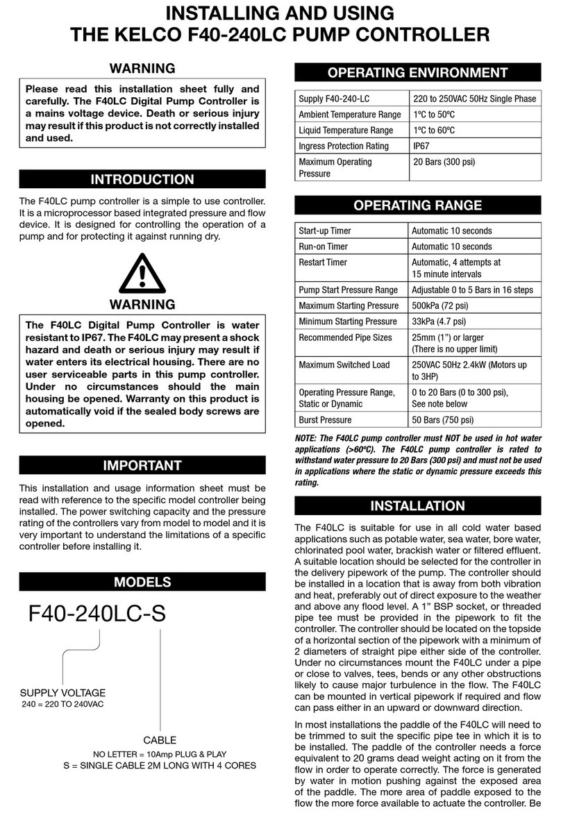
The F30 pump controllers require both electrical and mechanical
fitting. Installation or servicing of these controllers should only be
carried out by competent qualified personnel familiar with hydraulics,
pump fitting and with electrical control circuitry.
GENERAL NOTES
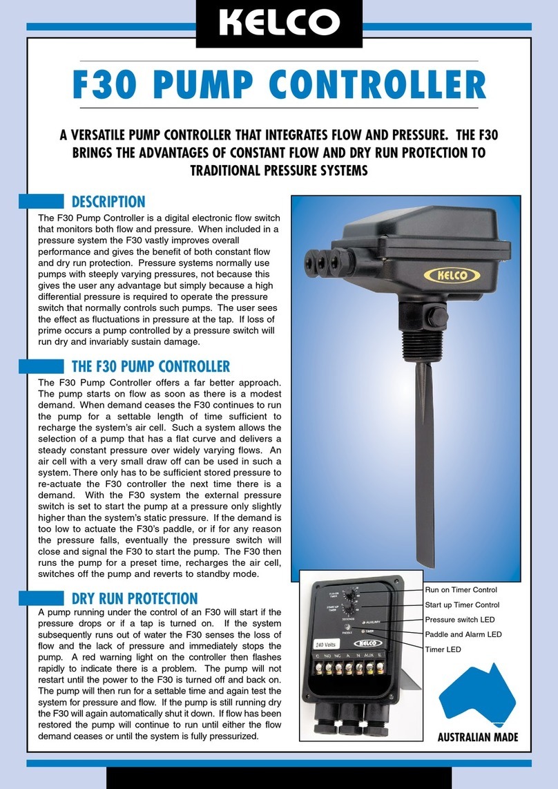
The F30 pump controllers are normally used to give dry run protection to
pressure pump systems. By using the system’s existing pressure switch,
a normal pressure start pressure stop pump can be converted to either
a pressure start flow stop or a flow start flow stop system. This gives
some major benefits in the way the pump performs in comparison to a
conventional pressure start pressure stop pump system. In addition to dry
run protection, such a system will supply a relatively constant pressure,
free from the cyclic pressure fluctuations that are characteristic of normal
pressure systems. No pressure cycling means a small draw off air cell
can be used, even on a large pump. Before installing the F30, a basic
decision needs to be made as to how you want the pump to operate. The
F30 can be mounted before or after the air cell to achieve totally different
operating characteristics.
INSTALLING THE F30 BEFORE THE AIR CELL
If the F30 is installed between the pump and the air cell and a tap is
opened, the air cell will supply the demand, large or small. The pressure
will drop and eventually the pressure switch will close, starting the
pump and supplying the demand. In other words there will be a delay
between turning on a tap and the pump starting. This delay will depend
on the draw off capacity of the air cell and the demand flow rate. This
configuration has the advantage that the pump will not start every time
a tap is turned on, but only if there is a genuine sustained demand for
water. This configuration is what is meant by “pressure start flow stop”.
This configuration is ideal for large pumps where there may be small or
frequent demands, such as in communal wash rooms. A large draw off
air cell is often used in such systems to further reduce the pump’s start
stop frequency.
INSTALLING THE F30 AFTER THE AIR CELL
If a tap is opened too much more than a trickle with this configuration,
the pump will immediately start, due to the paddle of the F30 being
pushed forward by the flow from the air cell. This is what is described
as “flow start”. With this arrangement the only time the system will
start on pressure drop is if there are leaks in the piping or a tap is left
trickling. In such a situation, the pump will automatically start when the
pressure switch eventually closes, re-pressurise the system and stop
after a time delay, under the control of the F30. The main advantage of
installing the F30 after the air cell is that the system will give an instant full
pressure start at a very constant flow every time a tap is turned on. This
configuration is ideal for small irrigation systems, gardens and household
use. Where a gravity fed hot water system is installed, the hot and cold
cycling in showers that plague normal pressure pumps are eliminated
with this configuration.
INSTALLATION
Having decided which basic configuration to use, follow the notes below.
Set out are some circuit examples and some essential details on installing
and adjusting the F30.
A suitable location should be selected for the controller in either the suction
or delivery pipework of the pump. The controller should be installed in a
location that is away from both vibration and heat, preferably out of direct
exposure to the weather and above any flood level. A 1” BSP or larger
socket must be provided in the pipework to fit the controller. The socket
should be located on the topside of a horizontal section of the pipe with
at least 5 diameters of straight pipe either side of the controller. Under
no circumstances mount the controller upside down under the pipe, or
close to valves, tees, bends or any other object likely to cause major
turbulence in the flow.
CHECK VALVE
ISOLATION VALVE
SUCTION PIPE
PUMP
SERVICE
PRESSURE
SWITCH
BLEED VALVE
AIR CELL
ISOLATION
VALVE
F30HD
FLOW
TYPICAL LARGE INDUSTRIAL OR RURAL PUMP INSTALLATION
In most installations the paddle of the controller will need to be trimmed
to suit the specific pipe in which the unit is to be installed. The paddle of
the controller needs a force of around 15 to 20 grams acting on it from
the flow in order to operate correctly. High velocity flow can generate high
forces and damage or break the paddle. As a general guide the paddle
of the controller should extend to around the centre line of the pipe, or
a bit past the centre. The paddle would not normally be left longer than
this unless the expected flow velocity was very low. Cut the paddle so
it extends to about the centre line of the pipe, or a little past the centre
when screwed into its socket. Ensure the paddle will clear the sides of
the socket and has enough room to swing back and forward freely. Apply
Teflon tape or a suitable thread sealant and screw the controller into the
socket using the spanner flats provided. Do not twist the body of the
controller or use it to screw the unit into the socket, as to do so may
damage the housing. When properly installed there should be a gap of
at least 4mm between the top of the 1”BSP thread and the under edge
of the spanner hexagon. Under no circumstances should the thread
be allowed to bottom out in its socket as to do so places the thread in
tension and may result in the controller housing cracking under pressure.
A quick release fitting can be used between the F30 and the pipe tee,
as shown in the accompanying drawing. This makes maintenance and
removal very simple.
FLOW
PREFERED LAYOUT, WITH PIPE WORK HORIZONTAL AND LEVEL
4mm MINIMUM
SEE NOTES
PADDLE CUT TO HALF WAY
ACROSS PIPE
F30 MOUNTED IN A PIPE TEE
FLOW
PADDLE CUT TO HALF WAY
ACROSS PIPE
4mm MINIMUM
ANKA QUICK COUPLING
QLCM40 & QLCF40
40 BY 25 REDUCING BUSH
CONTROLLER MOUNTED IN THE MIDDLE OF 10 DIAMETERS OF STRAIGHT PIPE
F30 MOUNTED IN A QUICK RELEASE COUPLING
SUCTION
DISCHARGE
PRESSURE
SWITCH
PUMP
AIR CELL
F30HD
F30HD MOUNTED BEFORE THE AIR CELL
F30 INSTALLED BEFORE
THE AIR CELL
SUCTION
DISCHARGE
PRESSURE
SWITCH
PUMP
AIR CELL
F30HD
F30HD MOUNTED AFTER THE AIR CELL
F30 INSTALLED AFTER
THE AIR CELL
INSTALLATION AND OPERATING OF F30 PUMP CONTROLLERS
C
NO
NC
A
N
AUX
E
PUMP
MOTOR
A1
A
2
A3
N
E
OPTIONAL
EXTERNAL
ALARM
415V 3 Phase Supply
Isolation switch,
used to reset
the F30HD
CONTACTOR
Pressure
Switch
F30HD
3 PHASE PUMP WIRING DIAGRAM
C
NO
NC
A
N
AUX
E
N
E
A
MAIN ISOLATION SWITCH
PRESSURE SWITCH
F30HD
240V AC SUPPLY
MAXIMUM MOTOR SIZE
3.75kW 5HP
PUMP
MOTOR
SINGLE PHASE WIRING DIAGRAM
C
NO
NC
AUX
E
PUMP
MOTOR
-
+
+
-
AC or DC
SUPPLY TO PUMP
PRESSURE
SWITCH
ISOLATION SWITCH
USE TO RESET THE
CONTROLLER
CONTACTOR
12 to 24 VDC Supply
F30-DC
F30-DC WIRING DIAGRAM
ELECTRICAL
The F30 flow switch requires a stable supply voltage in order to operate
correctly. Pay particular attention to cable sizes, and ensure cables are
adequate for the specific pump motor load. This is particularly relevant
where long cable runs are to be used in the installation. If the voltage
drop associated with the pump motor starting is excessive the F30 will
reset, and may cause the pump to jog. Jogging can snap a pump shaft
very quickly, so please take all precautions to ensure the voltage supply
to the F30 is stable and adequate for the job. Supply voltage must be
within the limits set out in the table below.
VOLTAGE RATING
MODEL MAXIMUM SUPPLY
VOLTAGE
MINIMUM SUPPLY
VOLTAGE
F30-240HD
F30-240
260V AC 160V AC
F30-24HD
F30-24
18V AC 28V AC
F30-DC 24DC 10V DC
IMPORTANT NOTES:
Never connect a DC load across the normally open terminals of the F30HD.
These controllers are only suitable for AC applications. The F30HD models are
designed for motor control and do not have voltage free contacts. To operate
properly all F30HD models require a minimum load of 10mA impressed
across the normally open terminals. The small leakage current across the
normally open terminals means the F30HD flow switches are not suitable for
driving small loads such as low wattage relays or electronic timers. For such
applications use a standard F30-240 or F30-24 flow switch. The F30-DC can be
used in AC or DC applications, its relay contacts are voltage free.
The F30-240HD and F30-24HD flow switches incorporate a solid state
drive to control a pump connected to their common and normally open
output terminals. The solid state drive enables very large pump motors
to be directly controlled, without the need for an interposing contactor.
The maximum size motor that can be controlled directly by the F30HD
flow switches is 3.75kW 5HP. At 240VAC the maximum recommended
continuous current load controlled by the F30HD must not exceed
16 Amps. The maximum motor starting current should not exceed 60
Amps.
Wire the system according to the model number of the controller and
the circuit schematics on this sheet. The F30 is normally connected to
an external pressure switch which must be set to cut in and out at the
correct settings before the controller can operate properly.
All F30 controllers have a single set of normally closed terminals, marked
“C” and “NC”, with a 16Amp 240V resistive rating. These contacts can be
used to control an external alarm or loss of flow warning light if required.
The F30-DC is essentially a control device that incorporates an S.P.D.T.
relay as its output. The F30-DC does have the capacity to directly
control small AC pump motors up to 0.75kW 1HP. For all DC motor load
applications, an interposing relay must be used between the F30-DC and
the load.
Several examples of typical wiring arrangements are provided on this
installation sheet. The circuits provided are intended as a guide only
to show the most basic and common ways to connect an F30 pump
controller.
FUNCTIONS OF THE INDICATOR LIGHTS
PADDLE LIGHT (3) FUNCTION
GREEN
Indicates that the paddle is in the flow
position. Normally off, this light turns
green as soon as flow pushes the
paddle forward. The pump will be on
whenever this light is green.
SLOW RED PULSE
Blinks red every 2 seconds to indicate
power is on. This light will blink red
whenever the power is on but the
pump is off.
RAPIDLY FLASHING RED
This light flashes rapidly red to indicate
that the pump has been run dry and
the F30 has shut it down. The blue
auxiliary light will also be on indicating
the pressure is low.
TIMER LIGHT (4) FUNCTION
GREEN
Provided the start-up timer is not set
to zero, this light indicates the start-up
timer is running, only comes on when
the F30 is first powered up. The pump
will run while ever this light is on.
RED
Turns red to indicate the run-on timer
is running. Can only come on after the
start-up timer has timed out. Provided
the run-on timer is not set to zero, this
light will turn red whenever the paddle
swings to the off position, indicating
flow has stopped. This light also turns
red whenever the pressure switch
closes. This red light can only ever be
on while the pump is running.
AUXILIARY LIGHT FUNCTION
BLUE
This light indicates the true status of
the remote pressure switch. It is on
whenever the contacts of the pressure
switch are closed. The pressure switch
contacts must be open and this light
off before the run-on timer times out.
If not, the F30 will shut down the
pump and go into alarm mode, with
the paddle light flashing rapidly red,
indicating dry run. Once in this mode,
the pump will not restart until the
power to the F30 is reset.
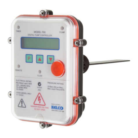
F30 CONTROL LAYOUT AND FUNCTION
1 START-UP TIMER Adjustable in steps from 0 to 180 seconds, runs
once only each time the controller is powered up or reset.
2 RUN-ON TIMER Adjustable in steps from 0 to 300 seconds. Can
be used to prevent the pump from cutting out on minor supply
interruptions as caused by air in the piping. Can also be used to
run the pump on after the flow stops, and pressurise pipes, or to
charge an air cell.
3 PADDLE status LED turns green whenever the paddle is on
(whenever there is flow), slowly blinks red when the controller is
in standby mode with the paddle off, to indicate the power is on
and the pump is being monitored. This LED also flashes rapidly red
in alarm mode, if the pump has run dry. Once in alarm mode, the
controller will not allow the pump to restart until the power to the
unit has been reset. This light is an excellent tool for setting up the
controllers and for diagnosing problems with the pump system.
4 AUXILIARY This LED turns blue to indicate the true status of a
pressure switch connected to the auxiliary terminal. When this LED
in on, the pressure switch contacts are closed, when it is off, the
pressure switch contacts are open.
5 TIMERS This LED turns green when the main timer is running,
which occurs each time the system is powered up. It also indicates
when the run on timer is running by turning red. When setting up
a controller this LED is essential because it allows you to observe
exactly how long the timers run after the paddle has been pushed
into the on position by the flow. It allows the timer dials to then be
correctly set to slightly longer than the time it takes for the paddle
LED to come on.
C Common output terminal. Power is normally looped into the
common terminal from the supply active.
NO Normally open terminal. A switch wire is normally run from this
terminal directly to the pump motor.
NC Normally closed terminal. Usually left unused, but can be connected
to an external alarm if required.
A Active terminal connects to the supply active, via an isolation
switch.
N Neutral terminal connects to the supply neutral.
AUX The auxiliary terminal accepts a switched input from an external
pressure switch. The switched supply to the AUX terminal should
be at the same voltage, and from the same phase as the main
supply to the controller.
E Earth terminal, isolated binding post for termination of earth wires.
5
30
60
60
5
0
30
TIMERS
PADDLE
RUN-ON
TIMER
START-UP
TIMER
SECONDS
NOC NC A N E
AUX
1
2
3
4
AUXILIARY 5
GENERAL LAYOUT OF F30 CONTROLS
PRESSURE SWITCH SETTING
A pressure switch is usually set to switch the pump on at about 140kPa
and to switch it off at about 420kPa. When used with an F30, the pressure
switch should be readjusted so it switches on at about 80 to 100kPa
above the system’s static pressure, and switches after a minimal rise in
pressure. Set the differential setting screw on the switch to the minimum
differential, and adjust the cut in pressure so that with the pump switched
off, the pressure switch closes its contacts before all the pressure
dissipates and it reaches a static pressure state. The object is to have
the pressure switch always close its contacts on a falling pressure before
all the pressure dissipates. By setting the differential to a minimum, you
ensure the pressure switch will open its contacts on a rising pressure just
after the pump starts. The F30 uses the state of the pressure switch to
identify if the pump is running dry. It is important to have the pressure
switch open its contacts before the run-on timer in the F30 times out. By
setting the differential to a minimum, you allow the full range of time delay
setting on the F30 run-on timer to be available for adjustment.
TIMER SETTINGS
Time delay adjustment is by means of two 16 position rotary switches.
The time delays are individually programmed into the controllers to give
the switches the following settings.
TIMER DELAY IN SECONDS
Start-up Timer 0, 1, 2, 3, 4, 5, 10, 15, 20, 25, 30, 40, 50, 60, 120, 180
Run-on Timer 0, 1, 2, 3, 4, 5, 10, 15, 20, 25, 30, 40, 50, 60, 180, 300
ADJUSTING TIMER SETTINGS
When adjusting the timer settings, the power to the controller must be
reset, that is, it must be turned off for a minimum of 1 second and then
turned on again, before the changes will take effect. This applies to all
the controllers.
BASIC FLOW SWITCH FUNCTION
The F30 pump controllers have two independent timers and are
individually adjustable in steps. With both timer dials set to zero, the
controllers behave like a basic flow switch, they respond solely to paddle
movement. On power up, the only indication of activity will be the paddle
light slowly blinking red to indicate the power is on. If the paddle is
pushed into the on position, the pump will start and the paddle light will
turn green. If the paddle swings to the off position (because flow stops),
the pump will stop and the paddle light will revert to slowly blinking red.
OVERRIDE ON START
On power up, the F30 will start the pump. The green timer light will also
come on and stay on for whatever time you have set the start-up timer
to. If the paddle is pushed into the on position by flow during the time
out period, the green paddle light will also come on. At the end of the
time out, the timer light will go out, but if the paddle is on, the pump
will continue to run. The green paddle light will remain on. If the paddle
subsequently swings to the off position because flow stops, the paddle
light will turn off and the pump will stop. The main paddle light will then
revert to slowly blinking red.
When running the controller in the override on start mode as described,
the main timer is normally set to slightly longer than the time required for
the paddle light to come on. By watching the timer light and the paddle
light and observing what happens on power up, it becomes a simple
matter to correctly set the timer.
RUN-ON TIMER
On power up, the pump will start, the green timer light will also come
on. If the paddle is pushed forward by flow, the green paddle light will
also come on. After the start-up timer’s initial time out, the green timer
light will go out but the pump will continue to run and the paddle light
will remain on, green. If the flow stops, the green paddle light will go
out and the timer light will turn on red indicating the pump is running on
the run-on timer. The pump will continue to run while the run-on timer is
running. If the paddle then swings back into the on position before the
run-on timer times out, then the pump will continue to run seamlessly.
If however the paddle fails to return to the on position by the time the
run-on timer times out, the pump will stop. The run-on timer’s red light
will go out and the green paddle light will also go out. If the paddle is
subsequently pushed back into the on position, the paddle light will again
come on and the pump will restart. Every time the paddle swings back
to the off position the run-on timer will re-run and keep the pump running
while it times out.
The main timer and the run-on timer function independently of each other
and are totally flexible. For example you can set the main timer to 3
seconds to get a pump started and the run-on timer to 2 minutes to run
a pump on and pressurise a pipe system or very large air cell. Alternately,
you could set the main timer to 3 minutes to allow a bore pump with a
self draining riser time to prime its riser, and you could also set the run-on
timer to 2 or 3 minutes to pressurise a feed line to a remote stock trough,
long after the main flow has reduced to a trickle.
In addition to the simple override functions the F30 controllers can accept
an input from an external switch, usually a pressure switch. When used,
the auxiliary input allows the controller to start on a falling pressure and
to identify a dry run situation. The F30 controllers also include an alarm
routine that locks out the pump in the event of dry running, preventing it
from restarting until the problem is fixed or the power is reset.
To use the auxiliary input, the pressure switch must be correctly adjusted,
and should be set so its low pressure contacts close on a falling pressure
at 8 to10M head pressure above the system’s static pressure. In other
words in a pressurised system with a slow leak, the pressure switch
contacts must close before all the pressure leaches away. In addition,
the pressure switch differential setting must be set to a minimum. The
object is to have the pressure switch start the pump only, and then for its
contacts to open as soon as the pressure starts to rise, and before the
run-on timer in the F30 controller times out.
Given that the pressure switch has been correctly set up and adjusted, in
a normal pumping system that has been running, and has stopped, the
F30 will function in the following manner.
The paddle light will blink slowly indicating power is on. If the pressure is
allowed to fall, for example if a tap is opened slowly so as not to actuate
the paddle, then as soon as the pressure reaches the cut in pressure
of the pressure switch, the pump starts. The blue pressure switch light
and the red run-on timer light will turn on. As the pressure rises, the
pressure switch contacts open, the blue light will go out and the pump
will continue to run under the control of the run-on timer. When the run-
on timer times out the pump will stop and the red run-on timer light will go
out. The paddle light will again blink slowly red. The net effect has been
to re pressurise the system. If over some period of time the pressure
is allowed to leach away again, the process will repeat, the pump will
automatically start, re pressurise the system and then stop and go back
into standby mode.
It is important to note that the pressure switch is only used to start the
system, not to stop it as in a conventional pressure system. This means
the pump can function as a constant pressure system not constrained
by the need to pump up to a high cut-out pressure simply because the
pressure switch requires it. Taken one set further, a multistage pump can
be de-staged, or a pump with a substantially flat constant flow curve can
be selected to operate under the control of the F30. This can result in
substantial savings in running costs and in many applications provide a
highly useful constant pressure flow, free of the pressure fluctuations that
plague conventional pressure systems.
DRY RUN PROTECTION
The F30 will start a pump on a falling pressure, and it expects to see the
pressure rise as soon as the pump starts. At any time, during normal
running or during standby, the closing of the pressure switch contacts
will start the run-on timer running. If the run-on timer times out and the
pressure switch contacts have not opened, the F30 will go into alarm
mode. The pump will stop and the paddle light will turn red and flash
rapidly. In alarm mode the paddle is overridden and even if the paddle
is jammed in the on position the pump will not start. Normally in this
situation, the blue pressure switch light will also be on, indicating that the
pressure switch is closed and therefore the pressure is too low.
To restart the pump, turn the power off, wait for one second and turn
it back on. If the pump is running dry, the F30 will again time out on its
main timer, stop the pump and go back into alarm mode. With the pump
primed, reset the power and observe the blue pressure switch light. As
the pressure rises the blue light will go out and the pump will continue
to run under the control of the main timer. When the timer times out the
pump will stop and the paddle light will revert to slowly blinking red,
indicating all is well and the controller is in standby mode.
SENSITIVITY ADJUSTMENT
A sensitivity adjusting screw is provided for fine-tuning the controllers.
Under the end of the controller’s housing is a hex-headed plug that
covers the adjusting screw. Remove the plug and using a broad
bladed screwdriver wind the adjusting screw anticlockwise to increase
the sensitivity (reduce the flow rate needed to actuate the paddle.) As
supplied, the screw is wound fully in, and the controller set to its least
sensitive. The maximum sensitivity is reached with the screw wound out
to a point where the hex dust cover can still be refitted. Normally the
sensitivity screw should be left fully in. If the paddle has been trimmed
too short, the effect can be compensated for by winding the sensitivity
screw out a few turns.
CONTROLLING A TANK-FILLING PUMP
The accompanying circuit shows how to wire an F30 pump controller
to give a tank-filling pump loss of flow protection. With reference to
the circuit, when the tank is close to empty the float switch closes and
applies power to the “AUX” and “C” terminals of the F30. The pump
immediately starts and runs while ever the float switch remains closed.
When the tank is close to full the float switch opens, breaking power to
the “C” and “AUX” terminals. The pump immediately stops. The F30 is
powered independently of the float switch, through its “A” terminal, so it
will continue to run on its internal run-on timer in spite of the pump being
off. When the run-on timer times out the F30 will revert to standby mode
with its red light slowly blinking.
If the system is running and the tank is filling, and the pump runs dry,
due to lack of water or a broken pipe, the F30 paddle will swing to the off
position and the-run on timer will engage. The run-on timer will time out
and the F30 will stop the pump. This is in spite of the float switch being
closed and the tank calling for water. In this state the F30 will rapidly
flash its red light indicating it has been run dry. The system will not restart
until power to the whole system is reset.
C
NO
NC
A
N
AUX
E
PUMP
MOTOR
N
E
Isolation switch,
used to reset
the F30HD
F30HD
FLOAT
SWITCH
A240V AC
DRY RUN PROTECTION FOR A TANK FILLING PUMP
CONTROLLING A LOW YIELD BORE PUMP
An F30 pump controller can be used in many novel ways to control a
pump. The accompanying circuit diagram shows how to use a single
external timer to restart a borehole pump that has stopped on loss of
prime, due to low yield or high draw down.
C
NO
NC
A
N
AUX
E
N
E
A
LEVEL SWITCH
PUMP CONTACTOR
N/C AUX CONTACTS ON DELAY TIMER
F30 CONTROLLER
125mA
ISOLATION SWITCH
CIRCUIT FOR AUTO RESTART OF A TANK FILLING
SUBMERSIBLE BORE PUMP
A single external timer can be used to control the AUX terminal of an F30
pump controller that in turn restarts the pump after any required time
delay. With reference to the accompanying circuit, when the tank level
switch closes it powers up the F30 and immediately energises the pump
contactor, and starts the pump. The Normally Closed auxiliary terminals
of the contactor will open, so there will be no power to the external timer.
If the F30 controller drops the contactor out because of lack of flow, the
contactors auxiliary terminals will close and power up the external timer.
The timer will run for whatever it is set to, say 2 hours, before its contacts
close and power up the auxiliary terminal of the F30HD, restarting the
F30 and the bore pump. As soon as the pump starts, power is lost to
the external timer and its contacts open, dropping the power off the F30
auxiliary terminal. The bore pump runs on under the control of the F30.
If the bore draws down again, the process will repeat with the pump
restarting at whatever time interval has been set on the external timer.
If the bore is still dry when the external timer powers up the system,
the pump will only run for the time set on the F30 main timer, 1 to 180
seconds. In a normal situation the bore will recover during the external
timer’s delay, however if the bore remains dry it is highly unlikely that the
short and infrequent run time of the F30 will cause any damage to the
bore pump, and the user will become aware of the problem when he runs
out of water in the tank.
MADE IN AUSTRALIA BY
KELCO
KELCO ENGINEERING Pty Ltd ABN 20 002 834 844
Head Office and Factory: 9/9 Powells Road BROOKVALE 2100 AUSTRALIA
Postal Address PO Box 496 BROOKVALE NSW 2100
Phone: (61) 2 99056425 Fax: (61) 2 99056420
Email: [email protected] URLwww.kelco.com.au
PLEASE NOTE: Kelco Engineering Pty Ltd reserves the right to change the specification of this product without notice. Kelco Engineering Pty Ltd accepts
no liability for personal injury or economic loss as a consequence of the use of this product. All rights reserved copyright Kelco Engineering Pty Ltd © 2008
PN000588

Other KELCO Controllers manuals

KELCO F60 MK3 Assembly instructions

KELCO

KELCO F60 MK3 Assembly instructions

KELCO F30 User manual

KELCO

KELCO F30 User manual

KELCO PG20 Series Instruction Manual

KELCO

KELCO PG20 Series Instruction Manual

KELCO F29 MK3 Assembly instructions

KELCO

KELCO F29 MK3 Assembly instructions

KELCO F60 Installation manual

KELCO

KELCO F60 Installation manual

KELCO F60 User manual

KELCO

KELCO F60 User manual

KELCO F40 Series Guide

KELCO

KELCO F40 Series Guide

KELCO F40-240LC Guide

KELCO

KELCO F40-240LC Guide

KELCO F60 Mk2 Assembly instructions

KELCO

KELCO F60 Mk2 Assembly instructions

Popular Controllers manuals by other brands

Consort HRXSL Installation & Control Guide

Consort

Consort HRXSL Installation & Control Guide

Alpine CRM-1652RF owner's manual

Alpine

Alpine CRM-1652RF owner's manual

Aruba Networks 3000 Series manual

Aruba Networks

Aruba Networks 3000 Series manual

Hardi HC 9600 Operator's manual

Hardi

Hardi HC 9600 Operator's manual

TREND IQ251 installation instructions

TREND

TREND IQ251 installation instructions

VIPA System 300S manual

VIPA

VIPA System 300S manual

LS Smart I/O datasheet

LS

LS Smart I/O datasheet

Metronix ARS 2302 product manual

Metronix

Metronix ARS 2302 product manual

Athena S Series instruction manual

Athena

Athena S Series instruction manual

Audioaccess PX-700 Features

Audioaccess

Audioaccess PX-700 Features

Overland Storage NEO Agility 48 10GbE Card instructions

Overland Storage

Overland Storage NEO Agility 48 10GbE Card instructions

I2R Tech Lighting Solutions Moving Head Controller 2.0 user manual

I2R Tech Lighting Solutions

I2R Tech Lighting Solutions Moving Head Controller 2.0 user manual

Parker HAUSER HPLA Series user guide

Parker

Parker HAUSER HPLA Series user guide

Mitsubishi Electric MELSEC iQ-F FX5-4AD-PT-ADP Hardware manual

Mitsubishi Electric

Mitsubishi Electric MELSEC iQ-F FX5-4AD-PT-ADP Hardware manual

PAC 520 quick start guide

PAC

PAC 520 quick start guide

ITC VersiControl 22500-RGBW Series Install instructions

ITC

ITC VersiControl 22500-RGBW Series Install instructions

Martem TELEM-AGC-L user manual

Martem

Martem TELEM-AGC-L user manual

Elation SDC-6 V2 user manual

Elation

Elation SDC-6 V2 user manual

manuals.online logo
manuals.online logoBrands
  • About & Mission
  • Contact us
  • Privacy Policy
  • Terms and Conditions

Copyright 2025 Manuals.Online. All Rights Reserved.