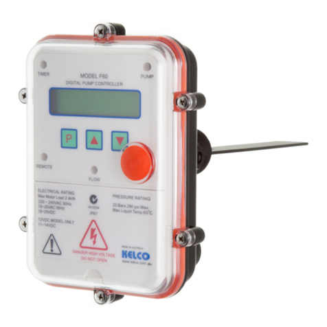
KELCO F60 User manual

KELCO F60
DIGITAL PUMP CONTROLLER
INSTALLATION INSTRUCTIONS
KELCO Engineering Pty Ltd
Sydney Australia
www.kelco.com.au
Version 180516

VERY IMPORTANT
This Kelco controller has been fully tested and calibrated. It is
presently unlocked and has a simple program loaded. It is set to
operate in a basic way with most of its special functions and features
switched o.
On start up this controller will run the pump using its start-up timer. If it
nds normal operating conditions in the pipe system it will continue to run
the pump. If pressure or ow conditions change the pump will continue to
run for a short period held on by the controller’s built in run-on timer. If
acceptable conditions fail to return the pump will be shut down after the
run-on time period. Pressing the red reset button on the controller’s lid or
resetting the power will repeat this basic process.
To change the functions of this controller please rst read the programming
book supplied with this unit.
IMPORTANT
DO NOT EXPOSE THIS CONTROLLER TO VIBRATION. INSTALL ONLY
IN PIPEWORK OR MANIFOLDS THAT DO NOT VIBRATE. Vibration will
damage the sensitive electronics within the controller and will void your
product warranty.

Table Of Contents
Warning Symbols Explained.......................................................... 1
Important Safety Instructions......................................................... 2
Overview........................................................................................ 3
Installing the F60........................................................................... 4
Before or After the Air Cell............................................................ 5
Warning Message.......................................................................... 6
Installation...................................................................................... 7
Aligning Paddle Assembly............................................................. 8
Locking the Electrical Assembly Onto The Paddle Assembly....... 9
Trimming the Paddle...................................................................... 10
Detaching the Electrical Housing.................................................. 11
Sensitivity Adjustment.................................................................... 12
Limitations...................................................................................... 13
Table of Limitations........................................................................ 14
Electrical........................................................................................ 15
The HD Heavy Duty Terminal........................................................ 16
Brownout or Blackout.................................................................... 17
Cable Gland Assembly................................................................... 18
Electrical Limits............................................................................. 19
Remote Input ................................................................................ 20
Wiring Diagrams ........................................................................... 26
The 12VDC F60 Pump Controller.................................................. 28
F60 Layout..................................................................................... 29
Table of Controls and their Functions............................................ 30
Maintenance, Spare Parts, Warranty............................................. 31

This symbol is intended to alert the user
to the presence of important operating
and maintenance instructions in the
literature accompanying the pump
controller
WARNING
This symbol is intended to alert the user
to the presence of un-insulated
“dangerous voltage” within the pump
controller’s enclosure that may be of
sucient magnitude to constitute a risk
of severe electric shock.
WARNING
1

IMPORTANT SAFETY
INSTRUCTIONS
• Read these instructions.
• Do not modify this controller in any way.
• Keep these instructions.
• Heed all warnings.
• Follow all instructions.
• Do not allow water to enter this controller.
• Install this controller per the manufacturer’s instructions.
• Do not install this controller near any heat source such as radiators, gas
heaters, stoves, or any other appliance that produces heat.
• Do not drill holes in this controller’s casing.
• Refer all installation and servicing to qualied service personnel.
• Servicing is required when the controller has been damaged in any way,
s u c h a s e x p o s e d t o r e , d r o p p e d , h a d o b j e c t s d r o p p e d o n i t o r b e e n
exposed to moisture or water when the controller’s lid is removed.
Please read these installation and operating
instructions fully and carefully before installing
or servicing this controller. The F60 Pump
Controller is a mains voltage device. Death or
serious injury may result if this product is not
correctly installed and operated.
WARNING
2

Overview
The F60 digital pump controller is a powerful exible controller that can be
congured in a variety of ways to control a pump and to protect it against running
dry. The controller can be set to operate in one of four fundamental modes. Within
each mode a number of functions can be selected using the controller’s simple
programmable interface. This document sets out in detail the installation and
functions of the controller and some of the main ways in which it can be used in
pumping and irrigation systems.
Without its lid in place the F60 is not water
resistant and presents a potential shock
hazard. Take great care not to splash water
onto the F60 when the lid is not in place.
Always replace the lid and fully tighten its 6
securing screws immediately after any
changes to the controller’s settings are
made.
WARNING
3

INSTALLING THE PUMP CONTROLLER
Location
Install this controller in a location that is sheltered from direct exposure to the
weather. The F60 is weatherproof; however, to ensure a long reliable life from the
controller we recommend it be protected from direct exposure to the sun and rain.
Intense sun light will eventually cause discoloration of the clear lid on the controller
and will also degrade its LCD screen. It is therefore advisable to always protect
the controller from the weather with some form of shielding.
The F60 should be installed in a straight section of pipe preferably with 5 diameters
of straight pipe either side of the paddle. The controller can be installed in a
suitable pipe socket, tapping saddle or pipe tee. The controller should be installed
in the discharge pipework of the pumping system, either before or after the
system’s air cell. If the system does include an air cell a decision has to be made
as to which side of the air cell to locate the controller. The fundamental way the
system operates will depend on this decision. The F60 should not be installed in
the suction pipe of a pump as it requires positive pressure to operate properly.
The F60 can be installed in either horizontal or vertical pipe. If it is installed in
vertical pipe the ow must be in an upward direction. Do not install this controller
on the underside of horizontal pipework.
4
DO NOT INSTALL THE F60 IN ANY LOCATION THAT EXPOSES IT
TO DIRECT SUNLIGHT. IN A FULLY EXPOSED INSTALLATION
ALWAYS PLACE SOME FORM OF SHIELDING OVER THE
CONTROLLER TO PROTECT IT FROM DIRECT EXPOSURE TO
THE SUN. FAILURE TO PROTECT THE CONTROLLER FROM
DIRECT EXPOSURE TO THE SUN MAY CAUSE IT TO OVERHEAT
AND MAY REDUCE ITS OPERATING LIFE.
VERY IMPORTANT

Before The Air Cell
If the F60 is installed before the air cell in the system it will only start the pump on
pressure since the initial draw o will be supplied from the air cell. The only
change in state the controller will see will be the falling pressure. Choose this
arrangement if you want to keep pump starts to a minimum and you are prepared
to accept the delay in starting associated with the slow pressure fall from the air
cell.
After The Air Cell
If you install the F60 in the pipework after the air cell the controller will start the
pump each time ow pushes its paddle forward or each time pressure falls to
whatever pressure you have set the controller to start at. Choose this arrangement
if you want the system to deliver a fairly steady pressure and to start each time
ow is sensed.
DISCHARGE
PUMP
AIR CELL
REMOTE
FLOW
TIMER
P
PUMP
SUCTION
CONTROLLER
CONTROLLER INSTALLED BEFORE THE AIR CELL
DISCHARGE
PUMP
AIR CELL
SUCTION
CONTROLLER
CONTROLLER INSTALLED AFTER THE AIR CELL
5

After programming the F60 always replace its lid
and fully tighten all 6 securing screws. Also ensure
all cable glands are fully tightened. Never leave
the lid o the controller for extended periods.
Without its lid in place the F60 is not water resistant
and presents a potential shock hazard. Take great
care not to splash water onto the controller when
the lid is not in place. Without its lid the controller
is not weather or insect proof and presents a
potential shock hazard that may result in death or
serious injury.
WARNING
6

Installation
The F60 pump controller is supplied as two separate assemblies, the paddle
assembly and the electrical housing. The paddle assembly should be installed in
the pipework rst and the electrical housing should then be tted onto the spigot
on top of the paddle assembly, taking care that the sealing O-ring is on the stem
and is in location and in good order. There is a at keying face on the cylindrical
body of the paddle assembly that keys the electrical housing onto the paddle
assembly and aligns it correctly. It is critical that the keying at is on the downstream
side and at 90 degrees to the axis of the pipework (see sketch). To secure the
electrical housing onto the paddle assembly an Allen head cap screw is supplied.
With the electrical housing located on the spigot and in position, press down with
the at of your hand on the top face of the lid of the electrical enclosure. While
pressing down, screw the 4mm Allen screw fully through the housing using the
3mm Allen Key (supplied). Tighten the screw and then release your hand from
the top of the housing. Pressing down with your hand on the housing preloads
the O-ring seal between the housing and the paddle assembly. It enables the M4
Allan screw to easily screw fully through the side of the housing.
Under no circumstances should the electrical housing be twisted or used to screw
the paddle assembly into the pipework, or to align the controller with the axis of
the pipework. To do so will irreparably damage the controller and void its warranty.
Never apply water pressure to the controller unless the M4 locking screw is in
place and fully tightened (see sketch for details). To t the paddle assembly into
the pipework use a suitable spanner and use the spanner ats provided on the
paddle assembly (directly above the process connection thread).
The F60 can be installed in either vertical or horizontal pipe. When installed in
vertical pipework ow must be in an upward direction past the controller’s paddle.
The F60 may have been supplied with either a ¾” or 1” BSP or NPT process
connection. A matching female threaded socket or pipe tee must be provided to t
the controller into pipework.
7

ALIGNING THE PADDLE ASSEMBLY
8

Locking the electrical housing onto the paddle assembly
LOCKING SCREW
USE 3mm A/F ALLEN KEY
(PROVIDED) TO LOCK THIS
SCREW SECURELY
CONTROLLER HOUSING
PADDLE
ASSEMBLY
PADDLE PIVOT
BOLT
9

Trimming the paddle
The paddle of the F60 can be cut down to suit the specic pipe size and intended
application. Cut the paddle using a hacksaw or tin snips so it clears the sides of
the pipe socket and protrudes approximately half to two thirds of the way across
the pipe when the controller is screwed into the pipework. If a low ow rate is
expected through the system the paddle should be cut longer, perhaps until it only
clears the bottom of the pipe by 5mm. If you are unsure as to what length the
paddle should be, a paddle trimming calculator is available at www.kelco.com.au
If you know what the expected ow rate is the calculator allows you to enter your
pipe diameter and paddle dimensions. It will then determine if the selected paddle
dimensions are adequate for the application. Spare paddles to suit the F60 pump
controller are available from Kelco or from your distributor.
Apply sealing compound or Teon tape to the process connection thread on the
controller and screw the controller into the pipework using the spanner ats on the
process connection. Do not screw the controller into the pipework by twisting the
electrical housing. The controller can be permanently damaged by twisting the
electrical housing. When correctly installed there should be a minimum 4mm gap
between the top of the pipe socket and the top of the thread on the F60. The
controller must be square to the axis of the pipework with the direction of ow
arrow pointing in the direction of ow.
10

Detaching The Electrical Housing
To allow easy access to the controller’s paddle, the electrical housing of the F60
can be detached from the paddle assembly. Removing the electrical housing
allows access to the paddle without the need to disconnect the electrical
connections to the controller. To remove the electrical assembly, switch o the
system’s power and undo and completely remove the M4 Allen head locking
screw (see diagram). Once the locking screw is removed, lift the electrical housing
straight o (do not twist it when doing this). Once the electrical housing has been
removed, the paddle assembly can be unscrewed from the pipework using the
spanner ats on the body of the paddle housing. Simply reverse this procedure
to ret the electrical housing to the controller, taking care to ensure the pressure
seal O-ring on the top of the wet end is in place and is clean and in good condition.
Always de-pressurise the piping system before removing the
electrical housing or carrying out any work on the paddle assembly
of the F60. The securing screw that locks the electrical housing onto
the paddle assembly of the F60 must never be loosened or removed
while the pipe system is under pressure. In order to carry out any
work on the paddle itself, the pipe system must be completely
depressurized and vented to atmosphere. If the F60 is located in a
section of pipework that is ooded then that section of pipework
must be tted with isolation valves and the valves must be fully
closed before removing the paddle assembly from the pipework.
WARNING
11

TYPICAL PIPE TEE INSTALLATION
REDUCING BUSH
PADDLE CUT TO CLEAR THE
INSIDE OF THE TEE
SENSITIVITY ADJUSTMENT
CABLE ENTRY
RESET BUTTON
DIRECTION OF FLOW
Sensitivity Adjustment
Under the end of the electrical housing on the F60 is a red hexagonal dust cap. If
you remove this dust cap you gain access to an adjustment screw that allows the
paddle preload to be reduced. As supplied the sensitivity adjustment screw is
wound fully in.
In this position the paddle is at its least sensitive. In this position it takes a
substantial force from the moving water to move the paddle. If you wind the
sensitivity adjustment screw anti-clockwise (outward) the force against the paddle
that resists ow will be reduced.
The paddle will become increasingly more sensitive and will respond to
progressively lower and lower ows the further out you wind the adjusting screw.
The total adjustment range is 10 turns of the screw. If you wind the adjustment
screw out beyond 10 turns there will not be enough residual force to return the
paddle to the o position when ow stops.
The range of sensitivity adjustment will also be aected by the orientation of the
controller. In horizontal pipework with the F60 mounted vertically the useable
range of adjustment is approximately 8 turns. In vertical pipe with the F60 installed
horizontally the full 10 turn range can be utilised.
12

Limitations
The F60 pump controller is water resistant to IP67. This rating only
applies if the clear lid and its gasket are in place and the lids 6 xing
screws are fully tightened. The F60 is not water resistant unless the
clear lid is in place and fully secured and all cable glands are correctly
assembled and tightened. Always replace the clear lid and fully
tighten the 6 securing screws after making changes to the controller’s
settings. The F60 may present a shock hazard and death or serious
injury may result if water enters the controller’s electrical housing.
There are no user serviceable parts in this pump controller. Under no
circumstances should the main electronics housing be opened.
Warranty on this product is automatically void if the electronics
compartment is opened.
WARNING
1 ) Do not install this controller in a fully exposed outdoor location. The F60 is
weatherproof, however, to ensure a long reliable life from the controller we
recommend it be protected from direct exposure to the sun and rain. Intense sun
light will eventually cause discoloration of the clear lid on the controller and will
also degrade the unit’s LCD screen. It is therefore advisable to always protect the
controller from the weather with some form of shielding.
2 ) Do not expose this controller to freezing. If the pipework in which the F60 is
installed freezes, the pressure sensor in the controller may fail. If the F60 is to be
used in areas where low temperatures will be encountered, always lag the pipework
for several metres either side of the controller and also lag the base of the controller
to prevent the unit and any adjacent pipework from freezing.
3) Do not use this controller in hot water applications. The F60 is not designed to
be used in water hotter than 60ºC.
4) Do not expose this controller to static or dynamic pressures greater than 20
Bars, 290 psi.
5) Do not install this pump controller in a section of pipe that is subject to vibration.
Vibration will cause premature failure of the electronic components within the
controller.
13

Operating Range
Ambient Temperature Range 1ºC to 50ºC
Liquid Temperature Range 1ºC to 60ºC See note below
Ingress Protection Rating IP67
Pre-Start Timer Adjustable from 1second to 4 minutes
in 1 second increments.
Start-up Timer Adjustable from 1second to 4 minutes
in 1 second increments.
Pressure Timer (Mode 4 Only) Adjustable from 1second to 15 minutes
in 1 second increments.
Run-on Timer Adjustable from 1 second to 15 minutes
in 1 second increments.
Pressure Dip Timer (Mode 4 Only) Adjustable from 1 second to 4 minutes
in increments of 1 second
Delayed Restarting (Modes 1 to 3 Only) Adjustable from 1 minute to 99 Hours
59 minutes in 1 minute increments.
Cyclic Running
Running and stopping times both
adjustable from 1 minute to 99 Hours
59 minutes in 1 minute increments.
Anti Cycling (Modes 1 to 3 Only) Adjustable from 1 motor start per hour
to 1800 starts per hour.
Run Dry Auto Restart (User Settable to
Single or Repeated Attempts)
Adjustable from 1 minute to 99 Hours 59
minutes in 1 minute increments.
Maximum Operating Pressure Static
or Dynamic 20 Bars 290 psi. See note below
Minimum Burst Pressure, all Models > 30 Bars 435 psi
Starting Pressure Range 0 to 2000 kPa or 0 to 290 psi in steps
of 1 kPa or 1 psi.
Stopping Pressure Range 0 to 2000 kPa or 0 to 290 psi in steps
of 1 kPa or 1 psi.
Minimum Pressure Dierential On to O 1kPa or 1 psi. Practical limit is nominally
10kPa or 1.5 psi.
Recommended pipe size 25mm 1” or larger. (There is no upper limit).
NOTE: The F60 must NOT be used in hot water applications >60°C. The controller
is rated to withstand water pressure to 20 Bars (290 psi) and must not be used in
applications where the static or dynamic pressure exceeds this rating.
14

Electrical
All electrical work associated with the F60
must be carried out by qualied electrical
personnel and all electrical work must
conform to AS/NZ standards and to local
wiring rules. For mains voltage applications
we recommend the supply to the F60 be
isolated by an RCD that has a maximum trip
current of 30mA.
WARNING
Introduction
The F60 is designed to directly control single-phase pump motors to 2.4kW. No
interposing contactor is required for such applications. If a supply neutral is
available the controller can also be used to control 3 phase pump motors via an
appropriate interposing contactor.
The F60 requires a 220V to 240V AC 50Hz supply when operated from the mains.
It can also be operated from an 18 to 24V AC or DC supply by utilising the low
voltage active terminal LV and common neutral terminal N (see the included wiring
diagrams). When operated from a low voltage DC supply the terminals LV and
neutral N are not polarity sensitive. The controller requires a stable supply voltage
in order to operate correctly. Pay particular attention to cable sizes, and ensure
cables are adequate for the specic pump motor load.
This is particularly important where long cable runs are to be used in the installation.
If the voltage drop associated with the starting of the pump motor is excessive the
F60 will automatically reset and this may cause the pump to jog. Jogging can
snap the main spindle of a pump very easily, so please take all precautions to
ensure the voltage supply to the F60 is stable and that the current carrying
capacity of the cable is adequate for the job.
15

The HD (Heavy Duty) Terminal
The HD terminal must be left unused or only ever be linked to the
relay terminal Relay 1 Normally Open. It must never be used for
any other purpose and it must never be connected to any external
device. Under no circumstances connect the HD terminal to the
terminals of Relay 2. The HD terminal must be regarded as live at
all times and at full mains potential.
WARNING
The F60 pump controller contains a solid-state switch (HD Heavy Duty
drive) that can be used to protect the contacts of Relay 1 by eliminating the
destructive arcing caused by the starting and stopping of pump motors.
The solid-state switch is accessible from the HD (Heavy Duty) terminal on
the terminal block. We recommend the HD drive be used whenever the
controller is used to directly control a pump motor. The HD drive should
not be used when the F60 pump controller is connected to external timers,
low wattage relays or to any other external device where voltage free
contacts are required. It is strictly intended for the direct control of highly
inductive AC motor loads. The HD terminal and the controller’s built in
relays must never be connected to a DC motor under any circumstances.
When the HD terminal is linked to the terminal Relay 1 Normally Open, the
HD drive in eect parallels a 40 Amp solid state switch across the relay’s
normally open contacts. This increases the momentary current carrying
capacity of the relay’s contacts to well over 60 Amps. The solid state HD
drive is only activated for a short period when the pump starts and stops.
It eectively handles the high inrush current associated with the pump
starting, and it provides a current path for the destructive back EMF
associated with the pump motor stopping.
To use the HD drive place a heavy link wire, 1.0mm or 1.5mm Sq between
the HD terminal and the Normally Open terminal of Relay 1.
16

Brownout Or Blackout
If a blackout or brownout occurs the F60 pump controller will not retain any
memory of where in its run or stop cycle it may have been, it will simply shut down
the pump. When power resumes, the F60 will reboot, restart the pump and run
any timer settings from the beginning. A manual reboot can be done at any time
by simply pressing the controller’s reset button.
Cables
The F60 has 3 X M20 cable glands. As supplied, the cable glands are blanked
o. To use the glands rst punch out the blanking barriers using a suitable punch.
The cable glands can accept cable from 7 to 9mm diameter. See attached sketch
for assembling the cable gland components. The controller is supplied with a set
of steel crimp rings. The crimp rings are to provide strain relief for the controller’s
cables. To use the crimps, place one on the cable approximately 3 to 4mm below
the end to the cable’s outer sheathing. Crimp the two ears of the ring at using
bull nosed pliers. Pull the cable back through the cable gland until the crimp ring’s
ears are fully located into the slots in the cable gland housing.
17
The F60 derives low voltage for its operation
from a non-isolated reactance power supply
(not through an isolated transformer). All
external devices connected to the F60
controller must be earthed and must be
regarded as operating at full mains potential.
WARNING
Other manuals for F60
1
Table of contents
Other KELCO Controllers manuals

KELCO
KELCO F30 User manual

KELCO
KELCO F40-240LC Guide

KELCO
KELCO F60 Installation manual

KELCO
KELCO PG20 Series Instruction Manual

KELCO
KELCO F29 MK3 Assembly instructions

KELCO
KELCO F40 Series Guide

KELCO
KELCO F60 Mk2 Assembly instructions

KELCO
KELCO F60 MK3 Assembly instructions

KELCO
KELCO F30 User manual