Kemper MINI-TRESOR User manual

DE Einbau- und Bedienungsanleitung
‘MINI-TRESOR‘ Wandeinbauschrank aus Edelstahl
Fig. 210 + Fig. 214 2
EN Installation and operating instructions
‘MINI-TRESOR‘ stainless steel built-in wall cabinet
Fig. 210 + Fig. 214 9
FR Instructions d’installation et d’utilisation
Armoire murale encastrée «MINI-TRESOR» en acier inoxydable
Fig. 210 + Fig. 214 15
IT Istruzioni di montaggio e d‘uso
‘MINI- TRESOR’ Armadio a incasso a parete in acciaio inox
Afb. 210 + Afb. 214 23
CS Návod k montáži a obsluze
‘MINI-TRESOR‘ vestavěná skříňka z nerezové oceli
obr. 210 + obr. 214 30
!

© www.kemper-olpe.de – 11.2021 / K410021000001-00 – 2 /36
DE Sicherheitshinweise für Montage und Gebrauch
Verwendung
Der Wandeinbauschrank dient als Versorgungssta-
tion zur zentralen Wasser- bzw. Stromversorgung.
Jede andere Verwendung gilt als nicht bestim-
mungsgemäß!
Anschlussmöglichkeiten: z. B. Wasser- und Strom-
anschluss für 230 V / 400 V, bauseits erweiterbar
z.B. um Gas-, Telefon-, Antennen- oder Abwasseran-
schluss, für die private und gewerbliche Anwendung.
Warnhinweise
Beachten und befolgen Sie die Warnhinweise in der
Anleitung. Nichtbeachten der Warnhinweise kann zu
Verletzungen oder Sachschäden führen!
Kennzeichnung wichtiger Warnhin weise:
Gefahr! Elektrischer Strom!
Kennzeichnet Gefahren, die schwe-
re oder tödliche Verletzungen zur
Folge haben können.
Warnung! Kennzeichnet Gefahren,
die zu Verletzungen, Sachschäden
oder Verunreinigung des Trinkwassers
führen können.
Hinweis! Kennzeichnet Gefahren,
die zu Schäden an der Anlage oder
Funktionsstörungen führen können.
Info! Kennzeichnet zusätzliche
Informationen und Tipps.
Wichtige Hinweise für den Anlagenbetreiber
Material: Edelstahl
Druckstufe Armatur: PN 16
Figur 214: speziell für chlorhaltige
Umgebungsbedingungen (z.B. Schwimmbäder)
Verwenden Sie das Gerät
- nur in einwandfreiem Zustand
- bestimmungsgemäß
Hinweis! Das Sicherheitstürschloss ist
umrüstbar auf ein bestehendes Schließ-
system. Das Türschloss ist ein Halbzy-
linder nach DIN 18252 / EN 1303, Hz35
/ Ø17. Hierzu ist das Türschloss
auszutauschen.
Hinweis! Die Elektro- und Sanitär-
installationen sind jeweils vom
Fachinstallateur auszuführen.
Montage und Gebrauch
Anleitung vor Montagebeginn oder Gebrauch sorg-
fältig lesen und den Anweisungen folgen! Montage
und Funktionsprüfung nur durch sachkundige,
qualizierte Fachkraft.
Anleitung an den Anlagenbetreiber weitergeben und
zur späteren Verfügung aufbewahren!
Warnung! Nationale Normen und Vorschriften zur
Sanitärinstallation sowie zur Unfallverhütung sind
vorrangig zu befolgen.
Hinweis! Einbauort muss ein geschlossener, trocke-
ner und frostfreier Raum sein, der nicht überutet
werden kann.
Hinweis! Vor Abschluss der Montage unbedingt
eine Dichtigkeitsprüfung der wasserführenden Ele-
mente sowie eine Funktionsprüfung durchführen.
Haftung
Keine Gewährleistung oder Haftung bei:
- Nichtbeachten der Anleitung.
- fehlerhaftem Einbau und/oder Gebrauch.
- eigenständiger Modikation am Produkt.
- sonstiger fehlerhafter Bedienung.

© www.kemper-olpe.de – 11.2021 / K410021000001-00 – 3 /36
DE
Hinweis! Der gesamte Tresor ist in
regelmäßigen Abständen mit einem
Edelstahlreinigungsmittel zu reinigen!
Pege der Schrankoberäche: Aggressive
und scheuernde Reinigungsmittel können
die Oberäche beschädigen. Keine chlor-
oder säurehaltigen, schleifenden oder
ätzenden Reinigungsmittel verwenden.
Die Reinigung wird mittels feuchtem
Mikrofasertuch empfohlen.
Hinweis! Die Verwendung als Verteiler
für Wasser und Strom ist nicht in allen
Ländern zulässig! Beachten Sie eventuell
bestehende landesspezische Regelungen,
falls Sie beabsichtigen, den Verteiler
außerhalb Deutschlands zu verwenden.
Hinweis! Bei Einbau des Tresors in
Schwimmbädern oder Einrichtungen mit
vergleichbaren Umgebungsbedingungen, ist
eine regelmäßige Reinigung des gesamten
Tresors, wie vorher beschrieben, notwendig.
Gefahr! Lt. VDE-Bestimmungen muss
der KEMPER MINI-TRESOR für Strom-
und Wasseranschluss durch einen
FI-Schalter (Fehlerstrom 0,03A)
abgesichert werden. Dies gilt für alle
Steckdosen im Außenbereich.
Bezeichnung
1Wandeinbauschrank (Grundkörper)
24 Befestigungsschrauben für Wandeinbaukasten (4,8 x 80)
3 Frostsichere Außenarmatur oder Geräteanschlussventil
42 Befestigungsschrauben (M6 x 12)
5 Steckdose je nach gewählter Figurnummer
6Montageplatte mit Befestigungsbügel
7 Flügelschrauben
8Blendrahmen und Tür mit Klappe
9Spritzschutzblech
10 2 Befestigungsschrauben (M6 x 12)
11 Türschloss mit 3 Schlüsseln
Entsorgung
Örtliche Vorschriften zur Abfallver-
wertung bzw. -beseitigung sind zu
beachten. Produkt darf nicht mit
normalem Haushaltsmüll, sondern muss
sachgemäß entsorgt werden.

© www.kemper-olpe.de – 11.2021 / K410021000001-00 – 4 /36
Hinweis!
Die Tiefe (T) min. 120 mm, max. 140 mm ergibt sich aus der
Wandstärke der Außenwand einschließlich Dämmung, Klinker etc.
Hinweis!
Zur Gewährleistung der Frostsicherheit der Trinkwasserarmatur
sind 150 mm Restwandstärke (1) erforderlich.
Hinweis!
Bei Verlegung der Anschlussleitung Unterputz ist eine
Mindestwandstärke von 285 mm (2) erforderlich.
Hinweis!
Die Armatur muss mindestens 250 mm über dem
höchstmöglichen Betriebswasserspiegel eingebaut werden!
Wärmedämmung gegen Kälteeinwirkung von außen
Für die Wandaussparung ist eine entsprechend ausreichende
Wärmedämmung in Abstimmung mit dem Architekten einzubauen!
(Die Dicke der Dämmschicht ist entsprechend zur Bestimmung
der Einbautiefe zu berücksichtigen!)
Zu berücksichtigender Brandschutz
Durch die Wandaussparung wird die Feuerwiderstandsdauer und die
Bauteilstärke der Außenwand herabgesetzt. Mit dem Statiker und dem
Brandschutzplaner ist ein Konzept zum Brandschutz für den Wandeinbau-
schrank (1) zu erstellen (Lösung für eine F 90 Wand: Ummantelung mit
40 mm Promatect H verwenden).
Es ist eine Maueröffnung mit den
Maßen 510 x 290 mm (H x B)
vorzusehen.
DE 1Maueröffnung | Wandaussparung

© www.kemper-olpe.de – 11.2021 / K410021000001-00 – 5 /36
Info! Folgende Figuren werden mit der Schutzart IP 55
ausgeliefert: 21002015CH I 21003015CH I 21004015CH
21412015CH I 21413015CH I 21414015CH
Beim Einpassen des Wandeinbauschranks (1) den späteren Wandaufbau der Außen-
fassade beachten. Max. Ausgleich von 20 mm durch den Blendrahmen möglich!
Kältedämmung ohne Brandschutzummantelung
Empfehlenswert ist eine rückseitige Dämmung (z.B. Styropor).
Rückseitige Dämmung einsetzen.
Schrank einsetzen und xieren.
Ggf. vier Löcher bohren und Schrank (1) mittels beiliegenden vier
Befestigungsschrauben (2) an der Rückwand befestigen
(vier Bohrungen, Ø 8 mm).
Metallende Gebäudeteile, zu denen auch der Tresor gehört benötigen
zwingend die Verbindung zum Potentialausgleich.
Querschnitt dieser Leitungen ist die Hälfte des Querschnitts des
Hauptschutzleiters, mindestens jedoch 6 mm².
Falls eine Brandschutzummantelung notwendig wird
Brandschutzummantelung in die Mauerwerksaussparung einsetzen.
Schrank (1) einsetzen.
* Für die Frostsichere Außenarmatur (3) ist eine Bohrung von
≥ Ø 27 mm erforderlich. Das im Wandeinbauschrank (1) vorgestanzte Loch
dient dabei als Schablone. Von innen nach außen ist ein Gefälle von max. 2 %
einzuhalten.
Stromzuführung vorsehen
- FI-Absicherung beachten:
Nennfehlerstrom ≤ 0,03 A und
Anschlussleistung ≤32 A
- Schutzart IP 44
Gefahr! Erdung!
Verbindung des Potential-
ausgleichs mit den dafür
vorgesehenen Schrauben
im oberen
Wandeinbauschrankbereich
und an der Tür herstellen
(sämtliche metallischen
Teile sind somit geerdet).
DE 2Montage Wandeinbauschrank
1.
1. 2.
2.
3.

© www.kemper-olpe.de – 11.2021 / K410021000001-00 – 6 /36
DE 34
Einbau
Steckdosenkombination Montage Frostsichere
Außenarmatur und Spritzschutz
Steckdosenkombination (5) (Anschlussfertig verdrahtet) auf
Montageblech (6) aufschrauben, im Wandeinbauschrank (1) anschließen
und mit der Flügelschraube (7) an der Schrankwand xieren
(20° schwenkbar).
Hinweis!
Funktionsprüfung durchführen!
Gefahr!
Elektroarbeiten dürfen nur von autorisiertem
Fachpersonal ausgeführt werden!
Warnung!
Montage nur durch sachkundige, qualizierte Fachkraft!
Hinweis!
- Wandscheibe bis zum Anschlag an das Auslaufgehäuse
schieben und mit Schraube justieren.
- Schlauchtülle und Adapter wie dargestellt montieren.
1.

© www.kemper-olpe.de – 11.2021 / K410021000001-00 – 7 /36
DE 45
Montage Frostsichere
Außenarmatur und Spritzschutz Montage Blendrahmen mit
Tür am Wandeinbauschrank
Frostsichere Außenarmatur (3) in die Bohrung stecken und mittels der
zwei beiliegenden M6-Schrauben (4) befestigen.
Außenarmatur (3) an die Wasserleitung anschließen
(Cu-Rohr Ø 15 mm oder AG R ½“).
Das Spritzschutzblech (9) mit der mittigen Bohrung (Ø 35 mm) unterhalb
der frostsicheren Außenarmatur einführen und mit den beigefügten
Schrauben M6 (10) an den vorgesehenen Befestigungspunkten an der
Rückwand verbinden.
Hinweis!
Ventilsitz (Gewinde R ½“) muss im frostfreien Bereich liegen.
Hinweis!
Angaben unter Punkt 1 Mindestwandstärken sind zu beachten!
Blendrahmen mit Tür (8) mit den seitlichen Führungsschlitzen über die
(vormontierten) Schrauben schieben, bis dass der Rahmen bündig mit
der Hausaußenwand anliegt.
Anschließend den Blendrahmen mit Tür (8) mit den Schrauben sichern.
Die integrierte Klappe für Schlauch- und Kabelanschluss dient zur Sicherheit
während des Gebrauchs.
Montage Aufputz Montage Unterputz
1. 1.
3.
2.
2.

© www.kemper-olpe.de – 11.2021 / K410021000001-00 – 8 /36
DE 6Funktionsprüfung
Funktionsprüfung der Frostsicheren Außenarmatur (3) durchführen.
Hinweis!
Durch das selbständige Entleeren der Frostsicheren Außenarmatur (3)
nach dem Zapfvorgang läuft das Wasser nach dem Absperren für
einige Sekunden nach (Frostsicherheit). Es ist aus diesem Grunde
nur leichtes Zudrehen (Schließen) der Armatur erforderlich.
Hinweis!
Zur Sicherstellung der Funktion „Frostsicherheit“ müssen Schläuche
und sonstige Anbauteile vor Beginn der Frostperiode entfernt
werden!
1.

© www.kemper-olpe.de – 11.2021 / K410021000001-00 – 9 /36
EN
Use
The built-in wall cabinet serves as a supply station
for the central water and power supply.
Any other uses constitute misuse.
Connection options: e. g. water and power connec-
tion for 230 V / 400 V, can be expanded on site, e.g.
by gas, telephone, antenna or waste water
connection, for private and commercial use.
Warning information
Please read and follow the warning information in
this instruction. Disregard of the warning informati-
on may lead to injury or material damage!
Labelling of important warning information:
Danger! Electricity!
Indicates hazards that might result
in severe or fatal injury.
Warning! Highlights risks that may
result in injury, material damage or
contamination of drinking water.
Note! Indicates hazards that may
lead to damages to the system or
malfunctions.
Info! Indicates additional
information and tips.
Important advice to the operator
Material: Stainless steel
Pressure rate valve: PN 16
Figure 214: especially for chlorine-based
environments (e.g. swimming baths)
Only use the TRESOR
- in sound condition
- as intended
Note! Note! The door lock can be
replaced with an existing locking system.
The door lock is a half cylinder according
to DIN 18252 / EN 1303, Hz 35 / Ø17.
The door lock must be replaced for this
purpose.
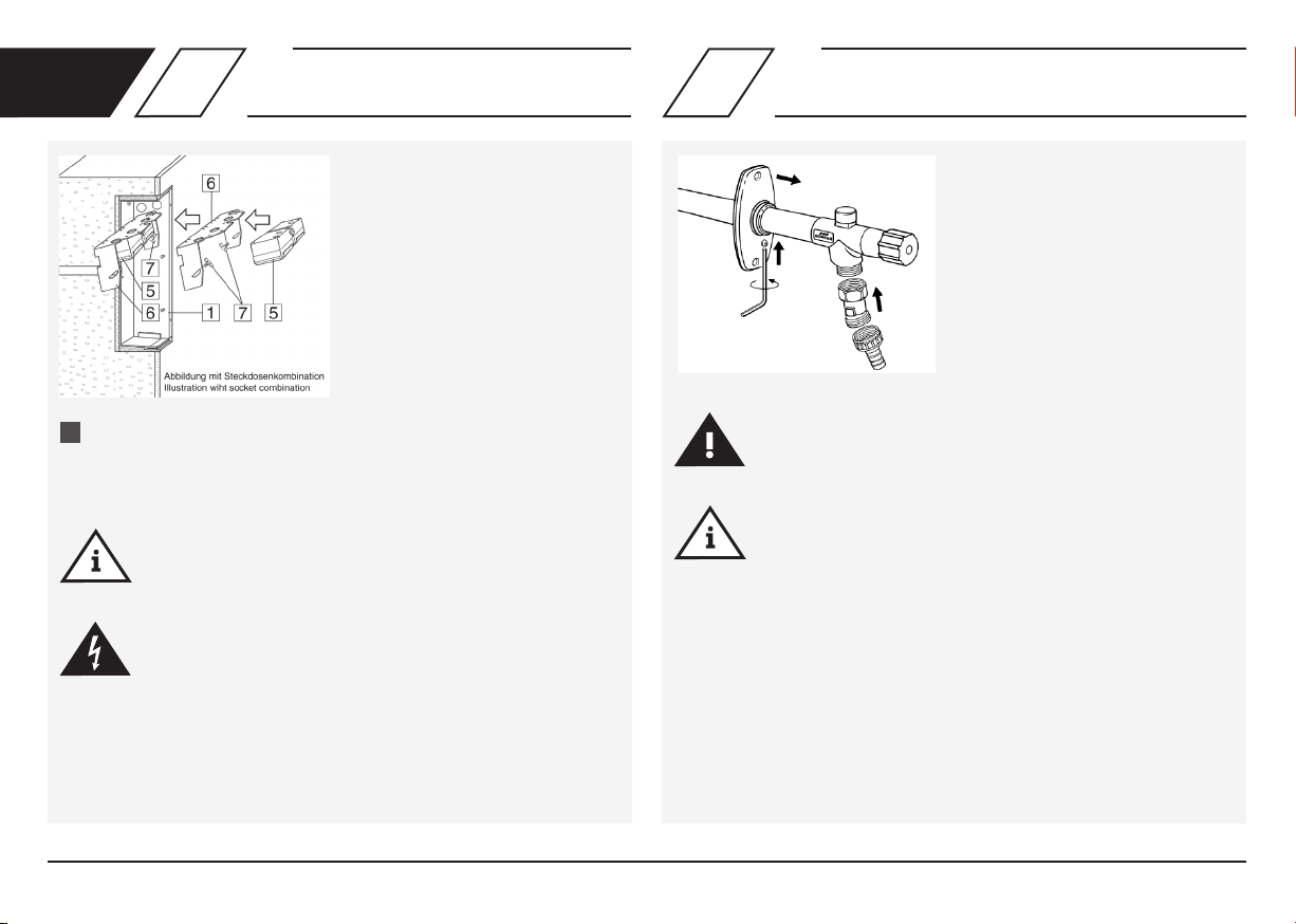
Note! The electrical and plumbing
installations must be carried out by
specialist installers.
Note! The complete Tresor must be
cleaned by a stainless steel cleaning
agent in regular intervals!
Care of the cabinet surface: Aggressive
and scour cleaning agents can damage
the surface. Don´t use chloric or acidic,
grinding or acidly cleaning agents.
Cleaningwithadampmicro-brecloth
is recommended.
Installation and operation
Read the manual carefully and follow the
instructions before installation!
Installation and maintenance must be
carriedoutbyqualiedplumbers.
Always pass on this manual to the current
system owner and keep it in a safe place for
future reference!
Warning! Priority must be given to the national
standards and provisions on sanitary
installations and accident prevention.
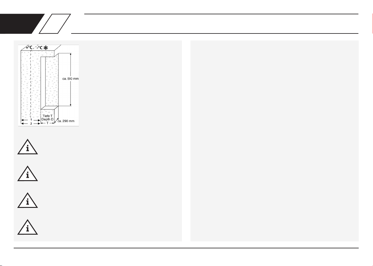
Warning! The installation location must be a closed,
dryandfrost-freeroomthatcannotbeooded.
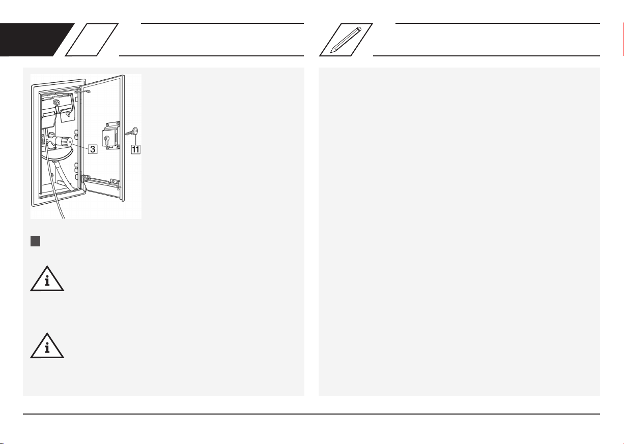
Warning! Before completing the installation, it is
essential to carry out a leak test of the water-bea-
ring elements as well as a functional test.
Warranty
Warranty or liability are voided through:
- Disregard of installation instructions.
- Damage due to faulty installation.
-Unauthorisedproductmodications.
- Other incorrect operation.
Precautions for installation

© www.kemper-olpe.de – 11.2021 / K410021000001-00 – 10 /36
EN
Note! In some countries the use of
combination units with water and
electric is not permitted. Please follow
thespecicregulationsfortherelevant
country, if you want to install the
product outside of Germany.
Note! In case of assembly the Tresor in
swimming pools or facilities with
compareable ambient conditions, a
regular cleaning of the complete Tresor
is necessary as described before.
Danger! According to VDE requirements
KEMPER MINI-TRESOR for power and
water connection have to fuse by a
residual current circuit breaker
(residual current 0,03A). This applies to
all sockets in outdoor area.
Disposal
Local regulations on waste
recycling and disposal must be
followed. The product must not be
disposed of with household waste
but must rather be disposed of
appropriately.
Description
1 Built-in wall cabinet (basic body)
2 4 attachment screws for built-in cabinet (4.8 x 80)
3 Frost-proof outdoor valve or hose bibb
4 2 attachment screws (M6 x 12)
5SockettotselectedFigurtype
6 Mounting plate
7 Wing-screws
8Trimframeanddoorwithap
9 Spray protection plate
10 2 attachment screws (M6 x 12)
11 Door lock with 3 keys

© www.kemper-olpe.de – 11.2021 / K410021000001-00 – 11 /36
A wall opening must be provided with
the dimensions 510 x 290 mm (H x W).
Note!
The depth (D) min. 120 mm, max. 140 mm is calculated from the
wall thickness of the outer wall including installation, clinker etc.
Note!
Inordertoguaranteefrostprotectionofthewatertting,awall
thickness (1) of 150 mm is required.
Note!
When laying the connecting pipe within the wall, a minimum wall
thickness of 285 mm is required!
Note!
The valve must be attached minimum 250 mm over the maximum
of operating water surface!
Heat insulation against the effects of cold from outside
Heat insulation must be provided for the wall opening in consultation with
the architect! (The thickness of the insulating layer must be taken into ac-
count accordingly for determination of the installation depth!)
Fire protection
Thewallopeningreducesthereresistancedurationandthestructural
strengthoftheouterwall.Areprotectionconceptforthebuilt-inwall
cabinet(1)mustbeproducedtogetherwiththesurveyorandre-
safety planner (Suggestion for an F 90 wall: Use lagging with 40 mm
Promatect H).
EN 1Wall opening | Recess

© www.kemper-olpe.de – 11.2021 / K410021000001-00 – 12 /36
Info!
FollowingguresaredeliveredwithprotectiontypeIP55:
21002015CH I 21003015CH I 21004015CH
21412015CH I 21413015CH I 21414015CH
Whenttingthebuilt-inwallcabinet(1),takeintoaccountthelaterwall
construction of the outer façade. Max. possible compensation by the trim
frame: 20 mm!
removethepre-stampedplatefortheoutertting
drill horizontally from outside to inside
Insulationwithoutreprotectionjacket.
Insulaiton on the back side is recommended (e.g. expanded polystyrene).
Insert rear insulation.
Insertthecabinetintotheopeningandxit.
If necessary, drill four holes and attach the cabinet (1) to the rear wall
using the four attachment screws provided (2) (four holes, Ø 8 mm).
Provide the power supply
- Note FI fuse:
Nominalfaultcurrent≤0.03A
andConnectioncurrent≤32A
- Protection type IP 44
Metallic parts of the building, to which the wall cabinet belongs, have
to be earthed.
The cross section of the wire is half the cross section of the main earth wire
of the building, or at least 6 mm².
If re protection lagging is necessary
Insertreprotectionlaggingintothemasonryrecess.
Insert the cabinet (1).
*Aholeof≥Ø27mmisrequiredforthefrost-proofoutertting(3).The
pre-stamped hole in the built-in wall cabinet (1) can be used as a template.
A slope of max. 2 % must be maintained from inside to outside.
Danger! Earthing!
Connect the earthing with the
intended screws at the upper
part of the wall cabinet and
the door (All metallic parts are
earthed by this).
1. 1.
1.
2. 2.
2.
3.
EN 2Installation of built-in wall cabinet

© www.kemper-olpe.de – 11.2021 / K410021000001-00 – 13 /36
EN 34
Installation of socket
combination
Installation of frost-proof outer
tting and spray protection
Screw the socket combination (5) (already wired) onto the mounting
plate (6), connect in the built-in wall cabinet (1) and attach to the
cabinet wall using the wing-screws (7) (20° swivel).
Note!
Carry out a functional check.
Danger!
Electrical work must be carried out only by authorised
specialist personnel!
Warning!
Installationmustbecarriedoutbyqualiedplumbers!
Note!
- Push the wall plate on to the outlet housing as far as the stop
and adjust using the screw.
- Fit the hose sleeve and adapter as illustrated
1.

© www.kemper-olpe.de – 11.2021 / K410021000001-00 – 14 /36
EN 45
Installation of frost-proof outer
tting and spray protection Installation of the trim frame with
door to the built-in wall cabinet
Insertthefrost-proofoutertting(3)intotheholeandattachusingthe
two M6 screws (4) provided.
Connecttheoutertting(3)tothewatersupply
(copper pipe Ø 15 mm or AG R ½“)
Insert the spray protection plate (9) with the central hole (Ø 35 mm)
belowthefrost-proofoutertting,andconnecttotheattachmentpoints
provided on the rear wall using the M6 screws provided (10).
Note!
The valve seat (thread R ½“) must be located in the frost-free area.
Note!
ThespecicationsgivenunderPoint1Minimumwallthicknesses
must be observed!
Push the trim frame with door (8) with the lateral guide slots over the
(pre-assembled)screws,untiltheframeliesushwiththeouterwallof
the building.
Then secure the trim frame with door (8) using the screws.
Theintegralapforhoseandcableconnectionisforsafetypurposesduringuse.
Exposed installation Concealed installation
1. 1.
3.
2.
2.

© www.kemper-olpe.de – 11.2021 / K410021000001-00 – 15 /36
EN 6Functional testing
Conductfunctionaltestingofthefrost-proofoutertting(3).
Note!
Duetotheautomaticdrainingofthefrost-proofoutertting(3)
after removal of water, water will continue to drain out for a few
secondsafterclosingthetting(frostsafety).Forthisreason,the
ttingonlyneedstobeclosedgently.
Note!
To ensure the correct ‘frost safety‘ function, hoses and other
attachements must be removed before the start of the frost
period!
1.

© www.kemper-olpe.de – 11.2021 / K410021000001-00 – 16 /36
FR Consignes de sécurité pour le montage
Remarques importantes
L’armoire murale encastrée sert de station centralisée
pour l’alimentation en eau et l’alimentation en électri-
cité Toute autre utilisation est considérée comme non
conforme à la destination prévue!
Possibilités de raccordement/ par ex. raccordement
d‘eau et d‘électricité pour 230 V / 400 V, qui peut être
étendu sur site par ex. par gaz, téléphone, antenne ou
raccordement d‘eau pour usage privé et professionnel.
Avertissements
Tenez compte et respectez impérativement les
avertissements de la notice. Le non-respect des
avertissements peut entraîner des blessures ou des
dommages matériels!
Marquage des avertissements importants:
Danger! Courant électrique! Indique les
dangers pouvant entraîner la mort ou
des blessures graves.
Avertissement! Indique les dangers
pouvant entraîner des blessures, des
dégâts matériels ou une contamination
de l‘eau potable.
Remarque! Indique les dangers pouvant
entraîner des détériorations sur l‘instal
lation ou des dysfonctionnements.
Info! Indique des informations
supplémentaires et conseils.
pour l’exploitant de l’installation
Matériau: Acier inoxydable
Niveau de pression de la vanne: PN 16
Figure 214: spécialement pour les environnements
chlorés (par ex. les piscines)
N’utilisez l’appareil
- que s’il est dans un état irréprochable et
- que conformément à la destination prévue
Remarque! La serrure à mortaise de
sécurité peut être adaptée à un système
de verrouillage existant La serrure de
porte est un demi-cylindre selon DIN
18252 / EN 1303, Hz35 / Ø17. À cet
effet, il convient de remplacer la serrure
de la porte.
Remarque! Les installations électriques
et sanitaires doivent être réalisées par
uninstallateurqualié.
Remarque! Le «Tresor» complet doit
être nettoyé à intervalles réguliers avec
un produit de nettoyage spécial pour acier
inox! Entretien de la surface de l’armoire:
Les produits de nettoyage agressifs ou
Montage et utilisation
Lisez soigneusement la notice avant le montage ou
l’utilisation et respectez les instructions! Seul un
technicienqualiéetcompétentenlamatièreest
autorisé à effectuer le montage et le contrôle foncti-
onnel. Remettez la notice à l‘exploitant de l’installa-
tion et conservez-la comme référence à l’avenir!
Avertissement! Les normes nationales, les régle-
mentations en matière d’installations sanitaires et
les prescriptions de prévention des accidents doivent
être suivies en priorité.
Remarque! Le lieu d’installation doit être un local fermé,
sec et à l’abri du gel, qui ne puisse pas être inondé.
Remarque!Avantlandumontage,effectuez
impérativement un contrôle d’étanchéité des élé-
ments conducteurs d’eau, de même qu’un contrôle
fonctionnel.
Responsabilité
Aucune responsabilité ni aucune garantie dans les
cas suivants:
- non-respect de la notice,
- installation et/ou d’utilisation incorrecte(s),
-modicationarbitraireduproduit,
- en cas de toute autre utilisation inappropriée.

© www.kemper-olpe.de – 11.2021 / K410021000001-00 – 17 /36
FR
Remarque! L’utilisation comme
distributeur d’eau et électrique n’est pas
autorisé dans tous les pays! Veuillez observer
les réglementations nationales éventuelles, si
vous souhaitez utiliser le distributeur dans
un autre pays que l’Allemagne.
Remarque! Dans le cas d’un montage
du «Tresor» dans les piscines ou installa-
tions présentant des conditions ambiantes
similaires, le nettoyage régulier du
«Tresor» complet est nécessaire,
conformément à la description ci-dessus.
Danger! Selon les dispositions VDE, le
«KEMPER MINI-TRESOR» pour branche-
ments électriques et d’eau doit être
protégé par un interrupteur de
protection contre les courants de
court-circuits (courants de fuite 0,03A)
Cela s‘applique à toutes les prises
électriques extérieures.
Désignation
1 Armoire murale encastrée (châssis de base)
24Visdexationpourcoffretmuralencastré(4,8x80)
3 Robinets extérieurs résistant au gel ou robinets extérieurs standard
42visdexation(M6x12)
5Priseenfonctiondunumérodegurechoisi
6Plaquedemontageavecétrierdexation
7 Vis papillon
8 Cadre et porte avec volet
9 Tôle antiprojections
10 2visdexation(M6x12)
11 2visdexation(M6x12)
abrasifs peuvent endommager la surface. Ne
pas utiliser des produits de nettoyage
chlorés ou acides, abrasifs ou corrosifs.
Nous recommandons d’utiliser un chiffon en
microbreshumidespourlenettoyage.
Mise au rebut
Il faut tenir compte des prescriptions
locales relatives au recyclage et à
l’élimination des déchets. Il est interdit
de jeter le produit dans les ordures
ménagères. Il faut, par contre, le mettre
au rebut de manière appropriée.

© www.kemper-olpe.de – 11.2021 / K410021000001-00 – 18 /36
Isolation thermique contre le froid provenant de l’extérieur
Pour la niche dans la cloison, il convient d’installer une isolation thermique
sufsanteconvenueavecl’architecte!(L’épaisseurdelacouched’isolantdoit
être prise en compte pour déterminer la profondeur de montage!)
Protection anti-incendie à prendre en compte
La niche diminue la durée de résistance au feu et la force portante du mur
extérieur. Établir un concept de protection anti-incendie pour le montage
de l’armoire murale encastrée (1) en concertation avec le maître d’ouvrage
etleplanicateurdelaprotectionincendie(solutionpourunecloisonF90:
revêtement avec 40 mm de Promatec H).
FR 1Ouverture dans un mur | Niche dans une cloison
Remarque!
La profondeur (p) minimale de 120 mm, maximale de
140 mm résulte de l‘épaisseur du mur extérieur, y
compris l‘isolation, la brique, etc.
Remarque!
Pour garantir la résistante au gel de la vanne d’eau
potable, une épaisseur de mur résiduelle (1) de 150 mm
est nécessaire.
Remarque!
Lors de la pose encastrée de la conduite d’alimentation,
l’épaisseur minimale nécessaire du mur est de 285 mm (2).
Remarque!
La vanne doit être installée au moins 250 mm au-dessus du
niveau d’eau de service le plus haut qui soit possible!
Prévoir une ouverture de
510 x 290 mm (h x l) dans le mur.

© www.kemper-olpe.de – 11.2021 / K410021000001-00 – 19 /36
Info!
LesguressuivantessontfourniesavecletypedeprotectionIP55:
21102015CH I 21109015CH
21412015CH I 21413015CH I 21414015CH
Lorsdelaposedel‘armoiremurale(1),tenezcomptedelaxationmuraleultéri-
eure. Le cadre permet de compenser une différence de niveau de max. 20 mm!
Isolation thermique sans revêtement anti-incendie
Nous recommandons une isolation entre l’armoire et le mur (en polystyrène par exemple).
Mettre en place l’isolation au fond de la niche.
Inséreretxerl’armoire.
Lecaséchéant,percerquatretrousetxerl’armoire(1)àlaparoiarrière
aumoyendesquatrevisdexation(2)fournies(quatretrous,Ø8mm).
Les éléments métalliques du bâtiment, dont le «Tresor» fait partie, requièrent
impérativement le raccordement à la compensation du potentiel.
La section de ces câbles correspond à la moitié de la section du conducteur
de terre principal et est au minimum de 6 mm².
Si un revêtement anti-incendie est nécessaire
Installer un revêtement anti-incendie dans la niche.
Insérer l’armoire (1).
* Pour le robinet extérieur résistant au gel (3), un trou de
≥Ø27mmestnécessaire.Letrouprédécoupédansl’armoiremuraleen-
castrée (1) sert de gabarit à cet effet. Prévoir une pente de max. 2 % allant
de l’intérieur vers l’extérieur.
Prévoir une alimentation
électrique
- Tenir compte de la protection
contre les courants de court-
circuits: Courant de fuite nominal
≤0,03Aetpuissanceconnectée
≤32A
- Type de protection IP44
Danger!
Mise à la terre!
Effectuer le branchement
de la compensation de potentiel
à l’aide des vis prévues à cet effet
dans la partie supérieure de l’armoire
murale encastrée et sur la porte (tous
les éléments métalliques sont alors
mis à la terre).
Montage de l’armoire murale encastrée
1.
1.
2.
2.
3.
FR 2

© www.kemper-olpe.de – 11.2021 / K410021000001-00 – 20 /36
FR 34
Installation de la combinaison Montage du robinet extérieur
résistant au gel et de la protection
Visser la combinaison prise (5) (câblée prête au raccordement) sur la
plaque de montage (6), la raccorder dans l’armoire murale encastrée (1)
etlaxeràlaparoidel’armoireàl’aidedesvispapillon(7)(pivotableà20°).
Remarque!
Effectuer un contrôle!
Danger!
Seuluntechnicienqualiéetagrééestautoriséàeffectuerles
interventions électriques!
Danger!
Seuluntechnicienqualiéetcompétentenlamatièreest
autorisé à effectuer le montage!
Remarque!
- Glisser le disque mural jusqu’à la butée sur le boîtier de sortie
et l’ajuster avec la vis.
- Monter le embout de tuyau et l’adaptateur conformément
à l’illustration.
1.
Other manuals for MINI-TRESOR
4
Table of contents
Languages:
Other Kemper Industrial Equipment manuals

Kemper
Kemper FK-5 User manual

Kemper
Kemper TRESOR User manual

Kemper
Kemper MINI-TRESOR User manual

Kemper
Kemper EVOLUTION LINE User manual

Kemper
Kemper KHS CoolFlow 612 04 001 User manual

Kemper
Kemper FK-5 Operating and maintenance instructions

Kemper
Kemper MINI-TRESOR User manual

Kemper
Kemper 712 99 001 User manual
Popular Industrial Equipment manuals by other brands

ProMinent
ProMinent Sigma SIBa operating instructions

CLEAN ROOM DEVICES
CLEAN ROOM DEVICES CRD221 Operator's manual

HMS Networks
HMS Networks Anybus Communicator PROFINET to EtherCAT... user manual

ESAB
ESAB A6 TPC 75 instruction manual

Nakanishi
Nakanishi NRR-3060 Operation manual

Dodge
Dodge Quantis MSM instruction manual