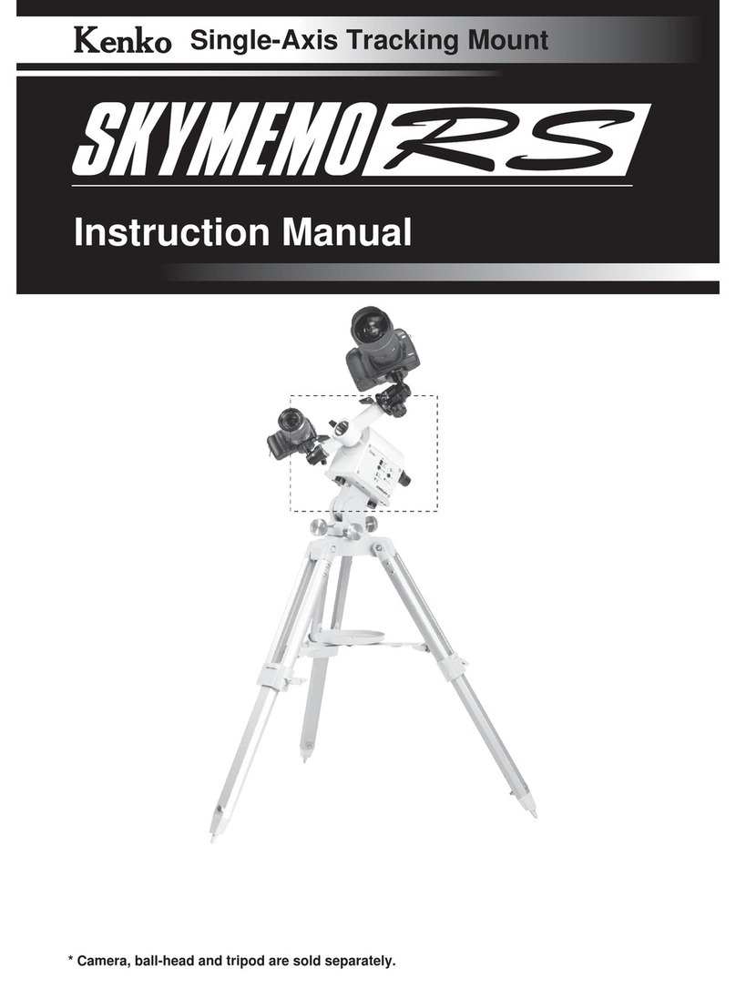
Kenko Sky Memo User manual

Kenko Sky Memo Instructions
Hutech Corporation © 2000
1
Kenko Sky Memo
Instructions
The Kenko Sky Memo (‘R’ version) is a single-
axis tracking system intended to be used in
wide-angle astrophotographic applications. In
the standard configuration, the system includes
a dual-camera tracking arm, illuminated polar
finder, and remote control paddle for guiding
use. All components included with the basic
tracker are pictured at right. An optional
compact tripod with fine attitude and azimuth
adjustments, or a counterweight bar with
various weights are also available.
Initial Preparation
The Kenko Sky Memo requires 4 C-cells to
be installed in the supplied battery holder,
which is then plugged into the side of the
tracker. Alkaline or carbon-zinc cells are
recommended, but NiCd rechargeable cells
may be used although the power light on the
side of the tracker may not light. If you plan
to photograph in cold weather, you should
prepare an insulated enclosure for the
battery pack to keep it warm enough to
function. The operating time for most
batteries are dramatically reduced below
freezing.
Because the Kenko Sky Memo can be
operated in either the northern or southern
hemisphere, the switch labeled “Direction”
must be set properly to the “N” or “S”
position respectively.
The polar finder illuminator should also be
inserted into the rear of the polar finder and
plugged into the illuminator power socket on
the tracker control panel.

Kenko Sky Memo Instructions
Hutech Corporation © 2000
2
Setting Up the Sky Memo Compact Tripod
The compact tripod is first assembled by spreading the legs
apart and setting the tripod in the standing position. Loosen
the joint screws at the top of each leg first, if necessary. The
leg stabilization struts can then be brought together in the
center where they should be held together by adding the
accessory tray as shown in figure at left.
Next, attach the head of the tripod, with its flat plate, to the
legs. A large black knob at the bottom of the head screws into the head through a
hole in the top of the tripod. Make sure the azimuth adjustment tab mates with the
gap between the two azimuth adjustment
screws. It may be necessary to loosen these
knobs to widen the gap enough to allow the
tab to fit in easily.
The Sky Memo tracker may then be placed on
top of the compact tripod plate and screwed
on using the provided thumbscrews. Secure
the tracker on the mount tightly enough so that
there is no play between the tripod and
tracker.
Next, extend the mount legs and lock them in
place. Tighten all joint screws to eliminate
any play in the tripod joints.
The tracker is now ready to be placed in approximate tracking position. Find a level location with firm ground and a
clear view of the polar region of your sky, and place the mount so that the polar finder is approximately lined up with
the pole. Use a compass or geographical landmarks and knowledge of your latitude to do the initial setup if
necessary. The purpose of this step is to line up well enough to place the necessary reference stars in the field of
view of the polar finder.
After setting the tripod down in approximate position, fine adjustment of the altitude or azimuth is via a pair of
adjustment knobs for each axis. These are located at the base of the head (near the top of the tripod). To adjust an
axis, unscrew the knob in the direction opposite to the desired direction, then turn the other knob to move to the
desired point. Once the desired point is reached, tighten the opposing knob to lock the mount in place.
Caution: Do not overtighten opposing knobs. The knobs are held onto the threaded
adjustment rods with a setscrew and by threading onto the rod with a thread of opposing twist
(left-handed screw). Overtightening a knob will likely cause the knob to be unscrewed from
the adjustment knob. If this happens, loosen the knob’s setscrew, screw the knob back onto
the threaded rod until the end is reached, and tighten the setscrew to prevent it from moving
further.
Continue setup in the “Camera Setup” section below.

Kenko Sky Memo Instructions
Hutech Corporation © 2000
3
Setting Up the Sky Memo on a Photographic Tripod
To use the Sky Memo tracker on a standard photographic tripod, the following tripod requirements should be satisfied:
•Good load capacity and stability
•Ability to rotate smoothly in azimuth and altitude
•Ability to lock the tripod position tightly
In general, a tripod of professional quality, such as a Bogen tripod, is
necessary to satisfy these requirements. The ability to smoothly adjust the
altitude and azimuth axes, and then solidly lock them in place is critical to
achieving good polar alignment for tracking.
To attach the tracker body onto the photographic tripod, use the ¼-20 screw
hole in the center of the bottom of the tracker. Most professional tripods also
have an additional stabilization screw or metal post which can be extended into
the holes provided for this purpose near the ¼-20 hole in the bottom of the
tracker body.
With the tracker attached to the tripod, place the combined unit in the observing spot. This location should be level,
on firm ground, and have a clear view of the polar region of the sky. To achieve the best stability possible, keep the
mount as low to the ground as possible (i.e. do not fully extend legs) and spread the legs of the tripod as far out from
the center as possible. Use any available additional material such as bags of sand or rocks around the tripod legs for
additional bracing.
Adjust the tripod pointing to align the polar finder approximately with the pole. Use your knowledge of the polar
constellations, a compass or geographical landmarks, and knowledge of your latitude if necessary. The purpose of
this step is to line up well enough to place the necessary reference stars in the field of view of the polar finder.
Camera Setup
Once you have roughly aligned the tracker, place the camera tracker arm onto
the polar axis with the clamp screws away from the tracker and tighten the
clamp as shown at right. Mount your cameras to the brass ¼-20 screws at the
end of the tracker arm. For flexibility in aiming each camera, the clamps at
each end may be loosened to allow the cameras to rotate. Adding a ball-head
between the tracker arm and camera for additional flexibility in aiming the
camera is possible, but not advisable as gradual slipping often occurs with
these types of heads.
If you are mounting a camera with a long telephoto lens on it, use a lens bracket
(left) to move the attachment point closer to the center of balance for the camera
and lens combination. Failure to do so may cause gradual slipping due to the
weight of the heavy lens.
To balance the tracker arm on the RA axis, the heavier camera should be on the
shorter side of the arm, which is designed to clear the top of the tracker body.
Check balance by carefully loosening the tracker arm clamp. Perfect balance is
not required. In fact, a slight imbalance to the east is actually best so that there
is no possibility of any mis-tracking due to gear backlash.

Kenko Sky Memo Instructions
Hutech Corporation © 2000
4
To mount a single camera, one of the camera mount screws on the tracker arm
maybe removed completely by unscrewing the clamping screw at the end of
the arm. Once the camera mount screw has been removed, the optional
counterweight and shaft may be screwed in place. Balance the camera by
adjusting the weight up and down the shaft until the tracker arm is
approximately in balance, but with a slight bias towards the east as mentioned
previously.
Setting Up for a Shot
To set up for a shot, power up the Kenko tracker by connecting the battery pack to the connector on the side of the
tracker body marked “Power.” Plug the polar finder’s illuminator into the socket marked “Light” on the side of the
tracker body. If the illumination level is too low to see the reticle markings or too high to allow you to see the
alignment stars, adjust it by turning the potentiometer marked “Vol.” Use a small flat-bladed screwdriver to adjust this
control. If the stars or reticle appear to be out of focus, turn the eyepiece of the polar finder until the stars and reticle
are simultaneously in focus.
Position the tracker arm and rotate the cameras to cover the desired targets. Be sure to allow for rotation of the
tracker arm during the exposure so that the cameras do not run into the tracker body. The arm rotates at the sidereal
rate of 15 degrees per hour.
Once the cameras are aimed, perform a fine adjustment of the polar alignment using the procedure in the document
“Kenko Polar Finder Instructions.” To insure best results, verify the polar alignment of the tracker between each
exposure.
The tracking accuracy you are able to achieve depends not only on accurate alignment of the mount, but also load
weight and balance, aim point, atmospheric refraction (at lower altitudes), and other factors. However, as a guideline,
the manufacturer-suggested maximum exposure times for unguided tracking for various focal lengths are:
Focal length
(mm) Max. exposure
(minutes)
50 70
100 40
135 35
200 30
300 15
For long focal lengths and shots at low altitudes where atmospheric refraction affects tracking, a small guide scope
should be used. In this case, the hand controller included with the Kenko mount should be plugged into the socket
marked “Control” located on the side of the tracker body. The buttons on the hand controller increase the tracking
rate to 2x sidereal rate or stop the motor, effectively giving a 2x forward or backward relative adjustment capability.

Kenko Sky Memo Instructions
Hutech Corporation © 2000
5
Specifications
Tracker:
Operation Northern or Southern hemisphere (switchable
by N-S switch)
Weight 3kg (Mount plus camera arm)
Dimensions240mm long x 90mm wide x 130mm high
Load capacity 2.5kg at each end. Total 5 kg.
Attachment M8 screws included for Kenko tripod or ¼-20
camera screw hole for standard photo tripod
Polar scope Magnification: 4X
Actual field of view : 10 degrees
Accuracy: better than 5’
Illuminated reticle, northern and southern
hemisphere operation
Polar scope filter thread M30.5/P0.5
Motor type Stepper
Gears 1:500, 1:2, Worm: 1:144
Hand controller 2X or stopped
Power 6VDC (4 c-cells)
Battery life >24 hours (Manganese batteries @ 20
degrees C)
Optional Tripod:
Height 600 to 800 mm
Weight 4 kg
Load capacity 10 kg
Azimuth range 30 degrees
Altitude range -10 degrees to 50 degrees

Kenko Sky Memo Instructions
Hutech Corporation © 2000
6
Troubleshooting
Below are some common problems encountered by photographers and some suggestions for troubleshooting a
setup:
Backlash in RA This is not problem. A little
backlash is necessary for proper
gear operation.
Kenko tripod adjustment knob
keeps turning without moving
position
lThe setscrew holding the
knob has loosened. lScrew the knob back onto the
adjustment shaft (it is a left-
handed thread) until it
reaches the end of travel and
tighten the setscrew
Can’t see reticle pattern well lPolar scope is not focused.
lIllumination is too low
lAdjust focusing by turning the
eyepiece
lAdjust illumination by turning
the VOL control
Stars are trailed lClamp(s) not locked firmly
lPolar alignment is off
lEquipment flexure
lAtmospheric refraction
lBattery power drops too low
lCamera or lens moved
lTighten clamps and recheck
before each exposure
lCheck polar alignment before
each shot
lWatch balance when using
longer and heavier telephoto
lenses (use lens bracket).
lUse a guide scope
lCheck to insure that the
motor is working properly,
use fresh batteries, and keep
batteries warm on cold nights
lCheck equipment position
before each shot to insure
tracker clearance. The arm
moves15 degrees per hour.
Image is out of focus lFocus ring moves during
exposure
lFilm move moves against
pressure plate in high
temperature and humidity
lUse tape to keep the camera
focus ring in position.
lShorten exposure times
lChange to a different film
lUse dry air purge for the
camera
Table of contents
Other Kenko GPS manuals
