KENT Glendale 32656 User manual

26'o Kent Glendale
Model # z 32656
Kent International: 1-800-451-5368
Date Purchaed:
Lot#:
)olf

I' , FoR SERVICE ASSISTANCE
CALL KENT TOLL FREE 1.800.451.5368
Monday - Friday 9:00 a.m. to 4:00 p.m. Eastern Standard Time
Congratulations on the purchase of your new bike! With proper assembly and maintenance it will offer you years of enjoyable riding!
I rvrpoRTANT:
Carefully read and follow this manual (ap any other materials included with this bike) before riding. Please retain this manual
for future use. If this bike was purchased for a child, it is the responsibility of the purchaser to veri$ the bike has been properly
' assembled, and that the user has been properly trained and instructed in use of the bike.
This manual is provided to assist you and is not intended to be a comprehensive manual covering all aspects of maintaining and
repairing your bicycle. The bicycle you have purchased is a complex piece of equipment that must be properly assembled and
maintained in order to be ridden safely. If you have any doubts about the assembly or your ability to properly assemble and maintain
the bicycle. You must have it assembled and maintained by a professional bicycle mechanic.
Check and read this decal on
your bicycle before each ride:
ALWAYS WEAR A PROPERLY FITTED
HELMET WHEN YOU RIDE YOUR
BICYCLE. DO NOT RIDE AT NIGHT. AVOID
RIDING IN WET CONDITIONS.
{ naNCfR! Failure to properly assemble and maintain your bicycle could result in serious injury or death to the rider.
WARNING!
ALWAYSWEAR
A HELMET
Mak€ Sure Stem
And PedalsAreTight.
(heckYour Brakes.
Do Not Ride At Night.
Read Owners Manual.
For A Free Owner's
Manual Or Questions
Call 1-800-451-5368
MADE IN CHINA

L
TABLE OF CONTENTS
Parts ldentification Graphics.......... """" 5-6
Before Riding 7-10
Assembly lnstructions....'........ ' 11-31
Maintenance........... '32-49
Wananty. "' 58
AwanNlNG/ cAUTloN
Throuqhout this manualYou will
see the words WARNING and
CAUTION. Please PaY sPecial
attention to this information, as it
could affect Your safetY al You
assemble and ride Your bike.
ilWNS WTIR I PROPTR1Y TITITII
lltltrltT wlltll You Rlllt Y0uR
BIGYGIT.ItO IIOT RIIIT [I IIIGHI.
lu0lll RllllllG lll ulH G0illllTl0lls.

v
CRUISER PARTS IDENTIFIGATION

COMFORT BIKE PARTS IDENTIFIGATION
Seat
Seat Post
Chain
Grips
Brake Lever
Handlebar
Stem
Head Set
Head Tube
Top T
Seat Mast
Seat Stay
Rear Hub
Chain Stay

v
RULES OF THE ROAD
ln the interest of safe cycling, make sure you read and understand the owner's manual.
Throughout this manual you will find WARNING, CAUTIONS, and NOTES or NOTICES.
WARNINGS: Pay special attention to these since failure to do so could result in injury to the rider or others.
CAUTIONS: lf not followed these could result in mechanical failure or damage.
NOTES or NOTICES: These specify something that is of special interest.
Before you ride this bicycle, read this RULES OF THE ROAD section and check that all parts are installed as per.this instruction manual.
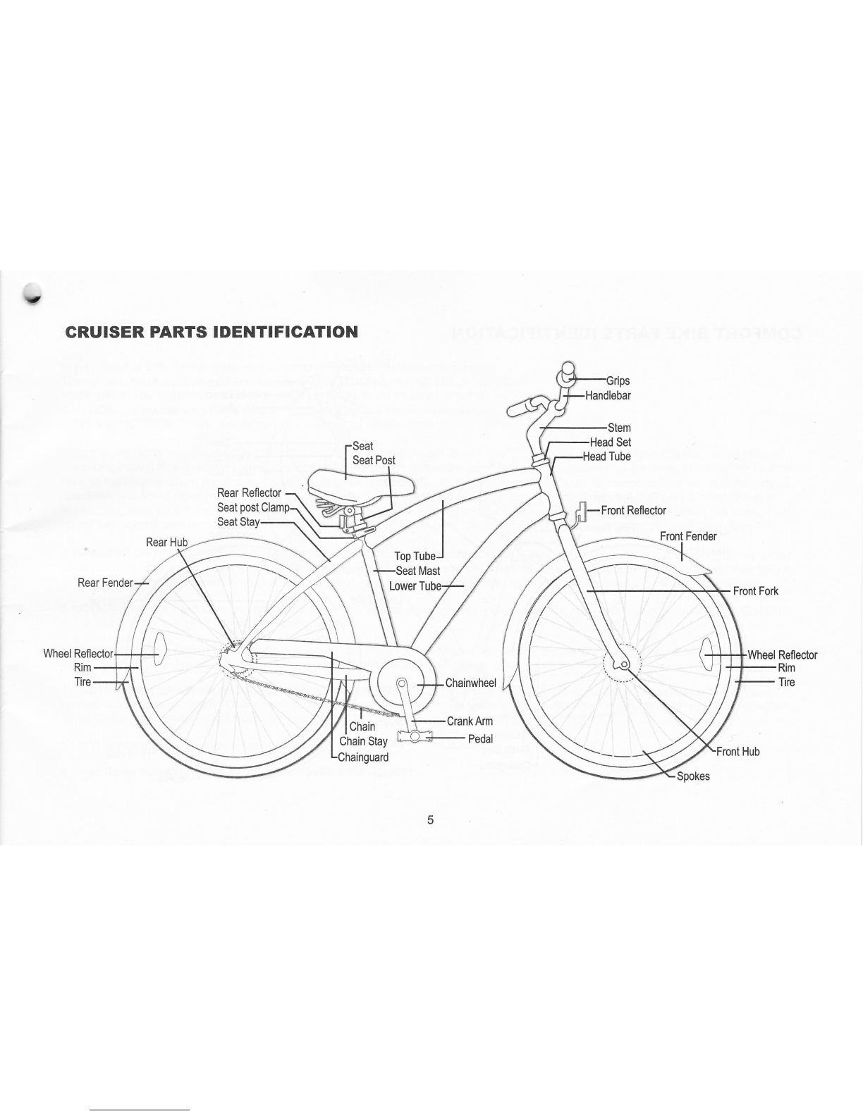
lf you understand how the bicycle operates, you will get the best performance. When you read this instruction book, compare the illustra-
tions to the bicycle. Learn the location of all the parts and how they work. Keep this book for future reference. Before you ride the bicycle,
check the brake and other parts of the bike. Make sure all pads are assembled correctly and working properly. Take your first ride in a
large, open, level area. lf you have a problem, check the assembly instructions and follow the maintenance procedures in this book. lf you
do not feel comfortable with your skills in assembling or adjusting the bike, please take your bike to a professional bike repairman.
1. WARNING ON AND OFF ROAD CONDITIONS: The condition of the riding surface is very important. lf the surface is wet, or has sand,
small rocks or other loose debris on the surface, carefully decrease the speed of the bicycle and ride with extra caution. lt will also take a
longer time and more distance to stop. Apply the brake earlier than normal and with less force to help keep the bicycle from sliding.
2. NOTICE: some state and local laws may require that your bike be equipped with a warning device, such as a horn or bell and a light. Do NOT
ride at night. Vision is quite limited at dawn and dusk.
3..Always wear shoes when riding a bicycle and avoid loose fitting clothes. Wear a cuff band or trouser clip to keep pants from getting caught in
the chainwheel. Long sleeves, long pants, gloves, eye protection and elbow and knee pads are also recommended.
4. CAUTION: WET WEATHER WARNING: Check your brakes frequently. The ability to stop your'bicycle is critical. Roads are slippery in wet
weather so avoid sharp turns and allow more distance for stopping. Brakes may become less efficient when wet. Leaves, loose gravel and other
debris on the road can also effect stopping distance.
5. Don't wear anything that restricts your hearing.
6. When riding, ALWAYS WEAR A CPSC APPROVED BIKE HELMET.

RULES OF THE ROAD continued
7. obey all traffic regulations. Most traffic regulations apply to bike riders as well as automobile operators. observe all state and local traffic
regulations, signs and signals. Check with your local police station on bicycle licensing and inspection, and where it is legal to ride your bike'
g. Keep to the RIGHT SIDE. Follow the traffic flow in a straight line close to the curb. watch out for opening car doors and cars moving in and out
of traffic. Use caution at intersections and keep both hands on the handlebars.
9. Never carry passengers. This is dangerous and it makes the bicycle harder to control. Never carry packages that can hinder your vision or
control of the bike.
10. when riding in pairs or in larger groups, form a single line along the right side of the road. Set up a sensible distance between riders' Don't
follow too closely.
11. Always be alert. Animals or people may dart in front of you. Give pedestrians the right-of-way. Don't ride too close to pedestrians, and don't
park your bicycle where it can get in the way of fooVvehicle traffic'
12. Be careful at all intersections. slow down and look bbth ways before crossing.
13. Use hand signals. Always let other drivers and pedestrians know what you are going to do. signal 100 ft. before turning unless your hand is
needed to control the bike.
14. WARNING: NIGHT TIME OpERATION: We do NoT recommend riding your bike at night. lf you have an emergency that requires you to ride at
night, you must have proper lights and reflectors. NEVER ride at night witn-olt a headlight,laillight, a white front reflector, a red rear reflector, pedal
reflectors and white wheel reflectors.
15. Cover your stem, handlebar, and top tube with safety pads for additional protection.
16. Never hitch rides. Never hold onto moving vehicles while riding. Never stunt ride or iump on your bike'
17. ON AND OFF ROAD OpERATIoN: Avoid the following road hazards: drain grates, pot holes, ruts, soft road edges' gravel' leaves (especially
when they are wet), uneven pavement, railroad crossings,-manhole covers, curbs, speed bumps, puddles, and debris call all have effect on your
riding and result in loss of control.
18. Do not ride your bicycle if the chain cover is not attached'

17 BEFORE RIDING:
Your new bicycle was assembled and tuned in the factory and then partially disassembled for shipping. The following instructions will enable you
to prepare your bicycle for years of enloyable cycling. For more details on inspection, lubrication, maintenance and adjustment of any area please refer to
the relevant sections in this manual. lf you have questions about your ability to properly assemble this bicycle, please consult a professional bicycle
mechanic belore riding.
* 5/6mm hex wrench
* Torque wrench
* Air pump & tire guage to inflate tires
* Bicycle lubricant or grease
RECORD SERIAL NUMBER
Each bicycle has a serial number stamped into
the bottom of the frame (See lllustration). Record
this number HERE to keep for future reference.
This number can be helpful to reclaim your bike
if ever lost or stolen. THIS INFORMATION lS
ONLYAVAILABLE ON THE BIKE ITSELF. There is
no record of your serial number at the store
purchased or with our company. lt is your responsibility
to record this information.
Serial Number:
Serial Number Location
Bike Shown Upside Down

n
-'-
GORREGT FR/AME SIZE
when selecting a new bicycle, the cbrrect choice of frame size is a very important safety consideration. Most full sized bicycles come in a
range of frame sizes. These sizes usually refer to the distance between the center of the bottom bracket and the top of the frame seat tube'
The ideal clearance will vary between types of bicycles and rider preference. This makes straddling the frame when off the saddle easier
and safer in situations such as sudden traffic stops. women can use a men's bicycle to determine the correct size women's model'
THERE SHOULD BE A CLEARANCE OF NO LESS THAN 1'2 INCHES BETWEEN THE
GROIN AREA OF THE INTENDED RIDER AND THE TOP TUBE OF THE BICYCLE' WHILE
THE RIDER STRADDLES THE BICYCLE WITH BOTH FEET FLAT ON THE GROUND.
THE SEATPOST "MINIMUM INSERTION" / "MAXIMUM
HEIGHT" MARK SHOULD NOT BE VISIBLE WHEN THE
SEAT POST IS INSERTED INTO THE SEAT MAST OF THE
BIKE. DO NOT RAISE THE SEAT POST BEYOND THIS
MARK. THE SEAT POST MAY BREAK CAUSING YOU TO
LOSE CONTROL AND FALL. ALWAYS CHECK TO MAKE
SURE SEAT POST ADJUSTING MECHANISM IS TIGHTENED
SECURELY BEFORE RIDING,
A
A
RIDING POSITION
SADDLE HEIGHT
ln order to obtain the most comfortable riding position and offer the best possible pedaling,e,fficiency'
iil;i-at ii"'Stif it'rortO be set conectly in relition to.the rider'sleg lgnstf:_Tl9-gorrect saddle herght
;h;i-d;;i;1i"; reg strainii6m over-6xtension, and the hips sholld nbt rock from side to side when
oedalino. While sittinq on tnJ'Oic-vl]e wiin one peOal at it's'lowest.point, place.the ball of your foot on
ih" ru:i iil ;"""i iiOOtL ne'gl'rt *itt allow the knee to be slightly bent in this position.
REACH
io 6btiin maximum comfort, the rider should not over extend his or her reach when riding. There.
;h"rta;" ;;iign] be"d i" ihe rideis eibows. Refer to the section regarding Seat and Seat posts to
learn how to adjust the seat post height.
Pedal
bottom position
Maximum Height /
Minimum lnsertion Mark
10

v
ASSEMBLING YOUR BIKE
PREPARATION
It is impodant that you read this owner's manual before you start to assemble your bicycle. WE RECOMMEND THAT YOU
CONSULT A PROFESSIONAL BICYCLE MECHANIC IF YOU HAVE DOUBTS OR CONCERNS AS TO YOUR ABILIry TO
PROPERLY ASSEMBLE, REPAIR, OR MANITAIN YOUR BICYCLE. Remove all parts from the shipping carton. Check to
make sure no parts are loose on the bottom of the carton. Carefully remove the front wheel which is attached to the side ol
the bicycle for shipping. Carefully remove all other packing material from the bicycle. This includes zip ties, axle caps and
material protecting the frame.
FRONT FENDER
lF your bike has fenders, it may be necessary to assemble the front fender to your
bike. The front fender is mounted at the fork crown. There are two methods to mount
your front fender. the first is the caliper brake mounting system, and the second is
the 1Omm nut and bolt system. ldentify the mounting system used on your bike and
follow the instructions below
1. lf your bike has a front caliper brake:
Remove the hex nut from the caliper brake bolt on the rear of the fork, and slide the
brake assembly onto the fork making sure the attachment holes and the fender
bracket holes line up. Reattach the caliper brake making sure that the brake arms
are on each side of the fender. Tighten the calipe brake bolt securely.
2. lf your bike does NOT have a front caliper brake:
Place the fender assembly onto the fork making sure the attachment holes and the
fender bracket holes line up. Attach the fender with the 1Omm hex bolt and nut
included. Tighten the bolt securely.
lf your fenders have stabilizer arms, attach the bottom of the stabilizer arm to the
bottom of the fork, using the washer and screw provided.

FRONT WHEEL
1. Remove the nuts, washers and wheel retainers from the front wheel axle, if necessary.
lf these are not on the wheel axle, they will be included i4 fte ftarO*are
2. Slide the wheel onto the open ends of the fork. Slip
an axle retainer onto each end of the axle, and hook
then retainers into the holes in the fork end' Loosely
install the washer onto each end of the axle (serrated
end toward the retainer), then intall the hex nut.
(Note: there may be a washer head nut in place of
the washer and hex nut).
3. Center the wheel in the fork and tighten the axle nuts
securely, alternating from one side to the other.
4. Spin the wheel to make sure that it is centered in the
fork and does not wobble. lf the wheel is not centered,
loosen the nuts and try again.
Torque requirement: 16-20 ft lbs.
LUGGAGE CARRIER ASSEMBLY
LUGGAGE CARRIER
REAR STABILIZER
FRONT STABITIZER
SEAT STAY
1) Align the REAR STABILIZER with the hole onto both sides on
the seat stay end
2) Align the FRONT BRACKET with the hole in the bracket located
on the seat stays
3) Mount the FRONT / REAR STABILIZER by using small bolts,
washers and nuts included, tighten securely.
LUGGAGE CARRIER
FENDER
SEAT STAY BRIDGE
SEAT STAY
FENDER STABILIZER
REAR DROPOUT
CHAIN STAY BRIDGE
CHAIN STAY
The rear fender is pre-mounted at the chain stay bridge and seat
stay bridge.Please follow the instructions below.
1 ) Remove the protecting material from fender.
3) Mount the fender stabilizer onto the rear dropout hole by using
the small screws included.Tighten the screws securely and evenly.
4) Make sure the nut on seat stay bridge be fully tightened'
REAR REFLECTOR ASSEMBLY
LUGGAGE CARRIER
RED REFLECTOR
'1) Align the rear reflector, make sure it is vertical to the ground
and points straight back.
2) Tight the screws fully.
REAR FENDER ASSEMBLY
12

v
QUIGK RELEASE FRONT WHEEL
Some bicycles have wheel axles that incorporate a Quick Release
(QR) mechanism. This allows easy wheel removal without the need for
tools. The mechanlsm uses a long bolt (called a skewer) with an
adjusting nut on one end, and a lever operating a cam-action tensioner
on the other.
With the quick release lever in the open position, insert the front wheel
into the open ends ofthe fork. Turn the adjusting nut so that the
locking lever is moved to the closed position with a firm action. At the
halfiruay closed positibn of the quick release lever, you should start to
feel some resistance to this motion. Do not tighten the quick release
by using the quick release lever like a wing nut. lf the quick release
lever is moved to the closed position with no resistance, clamping
strength is insufficient. Move the quick release lever to the open
position, tighten the quick release adjusting nut, and return the quick
release lever to the closed position.
Gorrect Quick Release Axle Setting
1. To set, turn the lever to the open position so that the curved
part faces away from the bicycle.
2. While holding the lever in one hand, tighten the adjusting nut
until it stops.
3. Pivot the lever towards the closed position. When the lever is
halfway closed, there must be firm resistance to turn it
beyond that point. lf resistance is not firm, open the lever and
tighten the adjusting nut in a clockwise direction.
4. Continue to pivot the lever all the way to the closed position
so that the curved part of the lever faces the bicycle.
13

KICKSTAND
Your bike will be equipped with either a standard kickstand, rear mount kickstand or no
kickstand. Please follow the instructions below that correspond with your bike.
1. Place the bicycle in an upright position.
2. Remove the top plate from the kickstand'
3. From the left side of the bicycle (opposite side from chainring), place the kickstand in
position beneath the two rear fork legs.
4. Place the top plate, flange down, onto the mounting bolt.
5. Replace the washer and nut onto the mounting bolt. Hold the kickstand arm in an up
position aligned with the frame stay, then securely lighten the mounting bolt.
6. Leave the leg of the kickstand down so it will support the bicycle during the rest of the
assembly process.
I wARN|NG! THE KICKSTAND IS DESIGNED TO SUPPORT THE BICYCLE ONLY NOT
Arxe rHE BrcYcLE AND RIDER.
REAR MOUNT KICKSTAND
Your bike will be equipped with either a standard kickstand, rear mount kickstand or no
kickstand. Please follow the instructions below that correspond with your bike.
1. Lean the bike against a wall for support, so that the the right side (chainring side) is
facing the wall and the left side of the bike is facing out.
2. Remove the rear axle nut and washer from the left side rear wheel.
3. Slide the kickstand plate onto the axle, so that it is seated against the rear dropout.
4. Slide the washer and nut back onto the axle and tighten securely.
5. Leave the leg of the kickstand down so it will support the bicycle during the rest of the
assembly process.
r WARNING! THE KICKSTAND lS DESIGNED TO SUPPORT THE BICYCLE ONLY NOT
Arne rHE BIcYcLE AND RIDER.
TOP PLATE
KICKSTAND LEG
14

v
PEDAL INSTALLATION
1. Apply a small amount of grease to the threads of each pedal. look
for the letter "L" or "R" on the side or end of each pedal spindle
(picture). Turning the spindle clockwise by hand (Picture), thread the
pedal marked "R" into the crank arm on the right (drive) side of the
bicycle. Make sure that you are not "cross-threading". which can sirip
the threads in the crank arm. lf the threads do not turn easily, don't
force them. Back the spindle out and start over. Once the pedal is
threaded into the crank arm, tighten the spindle securely to the crank
arm with a 15mm open end or an adjustable wrench.
2. Turning the spindle counterclockwise by hand, thread the pedal
marked "L" into the crank arm on the left side of the bike. Make sure
that you are not "cross-threading". which can strip the threads in the
crank arm. lf the threads do not turn easily, don't force them. Back the
spindle out and start over. Once the pedal is threaded into the crank
arm, tighten the spindle securely to the crank arm with a 15mm open
end or an adjustable wrench.
WARNING! IMPROPERLY INSTALLED AND TIGHTENED PEDALS
CAN WORK LOOSE, DAMAGING THE BICYCLE AND CAUSING
POSSIBLE SERIOUS INJURY OR DEATH TO THE RIDER.
Torque Requirement 1 5-18 ft. lbs.
15

'))
HANDLEBAR AND STEM INSTALLATION
QUILL STEM ASSEMBLY
1. Loosen the stem expander bolt, if necessary, so the wedge
nut is in line with the stem body. See illustration.
2. lnsert the stem into the head tube past the minimum insedion
line indicated on the stem.
A WARNING: THE HANDLEBAR STEM MUST BE INSERTED
A rruro rHE HEAD TUBE uNTrL THE MINTMUM rNsERTroN
LINE INDICATED ON THE STEM IS COMPLETELY COVERED.
3. Face the handlebar stem forward directly in line with the front
wheel. Make sure the fork is in the correct position (facing forward)
before tightening the expander bolt. See illustration on this page.
4. Tighten the expander bolt securely (turning in a clockwise
direction). Recommended torque is 20 ft lbs.
A WARNING: THE ASSEMBLER lS CAUTIONED AGAINST THE
A oancen oF DAMAGTNG THE HANDLEBAR srEM AssEMBLy
AND POSSIBLE INJURY TO THE RIDER IN OVERTIGHTENING
THE EXPANDER BOLT AND EXPANDER WEDGE.
HANDLEBAR INSTALLATION
1. Removethe stem cap bolts and stem cap.
2. lnsert the handlebar into the stem.
3. Reattach the stem cap by tightening the stem cap bolts
equally. Note the distance between the stem and stem cap should be
equal on top and bottom of the cap.
4. Check the handlebar for tightness. If you can move it forward or
backward, the cap bolt is not tight enough.
- Minimum lnsertion Line
€\
A --.1-Heaoruue
Cap Bolts
e
Expander Bolt
Stem
Wedge Nut
5. Check steering by siraddling the front wheel and trying to turn the handlebar. lf you can turn the handlebar
without turning the front wheel. The stem is too loose. Align the handlebar with the front wheel. Retighten the
expander bolt (clockwise). Recommended torque is 15 ft lbs.
Correct
lncorrect
't6

v
HANDLEBAR AND STEM INSTALLATION
STANDARD ONE PIECE STEM ASSEMBLY
1. Loosen the stem expander bolt, if necessary so the wedge
nut is in line with the stem body. See illustration.
2. lnsert the stem into the head tube past the minimum insertion
line indicated on the stem.
,T WARNING: THE HANDLEBAR STEM MUST BE INSERTED
A tnro rHE HEAD TUBE uNTrL THE MTNIMUM tNsERTtoN
LINE INDICATED ON THE STEM IS COMPLETELY COVERED.
3. Face the handlebar stem forward directly in line with the front
wheel. Make sure the fork is in the correct position (facing forward)
before tightening the expander bolt. See illustration on this page.
4. Tighten the expander bolt securely (turning in a clockwise
direction). Recommended torque is 20 ft lbs.
A WARNING: THE ASSEMBLER IS CAUTIONED AGAINST THE
Aonruoen oF DAMAGTNG THE HANDLEBAR srEM AssEMBLy
AND POSSIBLE INJURY TO THE RIDER IN OVERTIGHTENING
THE EXPANDER BOLT AND EXPANDER WEDGE.
HANDLEBAR INSTALLATION
1. Loosen the stem clamp bolt.
2. lnsert the handlebar into the stem.
3. Tighten the stem clamp bolt securely.
4. Check the handlebar for tightness. lf you can move it forward
or backward, the clamp bolt is not tight enough.
5. Check steering by straddling the front wheel and trying to turn the
handlebar. lf you can turn the handlebar without turning the front wheel.
The stem is too loose. Align the handlebar with the front wheel. Retighten the
expander bolt (clockwise).
Recommended torque is 15 ft lbs.
Clamp Bolt
Wedge Nut
lncorrect
17

HANDLEBAR AND STEM INSTALLATION
ADJUSTABLE STEM
1. Loosen the stem expander bolt, if necessary so the wedge nut is in
line with the stem body. See illustration.
2. lnsert the stem into the head tube past the minimum insertion line indicated
on lhe stem. WARNING: THE HANDLEBAR STEM MUST BE INSERTED
INTO THE HEAD TUBE UNTIL THE MINIMUM INSERTION LINE INDICATED
ON THE STEM LINE INDICATED ON THE STEM IS COMPLETELY COVERED,
3. Face the handlebar stem forward directly in line with the front wheel. Make
sure ihe fork is in the correct position (facing forward) before tightening the
expander bolt. See illustration on this page.
4. Tighten the expander bolt securely (turning in a clockwise direction).
Recommended torque is 20 ft lbs.
5. STEM ANGLE ADJUSTMENT. The stem angle can be adjusted from g0 to
145 degree angle. The adjustment screw is located UNDER the stem extension.
You will need a 5mm Allen Wrench. loosen the Smm Allen Screw. (DO NOT
remove the screw. loosen it only enough to allow angle adjustment.) Adjust
to the desired angle and tighten bolt securely. Check the stem for tightness
before ridins. WARNING: DO NOT TRY TO ADJUST THE SCREWS ON THE
SIDES OF THE STEM EXTENSION. WARNING: THE ASSEMBLER IS
CAUTIONED AGAINST THE DANGER OF DAMAGING THE HANDLEBAR
STEM ASSEMBLY AND POSSIBLE INJURY TO THE RIDER IN OVER.
TIGHTENING THE EXPANDER BOLT AND EXPANDER WEDGE.
HANDLEBAR INSTALLATION
1. Remove the stem cap bolts and stem cap.
2. lnsed the handlebar into the stem.
3. Reattach the stem cap by tightening the stem cap bolts equally.
be equal on top and bottom of the cap.
Expander Bolt
Angle Adjustment Screw
(Located Under Stem Extension)
Minimum lnstertion Line
Note the distance between the stem and stem cap should
Side Screw
(Do Not Adjust)
Cap Bolts
4. Check the handlebar for tightness. lf you can move it forward or backward, the cap bolts are not tight enough.
5. Check steering by straddling the front wheel and trying to turn the handlebar. lf you can turn the handlebar without turning the front
wheel. The stem is too loose. Align the handlebar with the front wheel. Retighten the expander bolt (clockwise).
Recomrnended torque is 15 ft lbs.
18

v
HANDLEBAR AND STEM INSTALLATION
A.HEAD STEM ASSEMBLY
1. lnsert the stem pillar into the fork tube to the minimum insertion
line indicated on the stem pillar.
2. Tighten the 6mm stem pillar bolt to a torque of 15 ft. lbs.
N WARNING: THE HANDLEBAR STEM MUST BE INSERTED
ANrd;;iEninoiueeuNrrLrHE MrNrMuillliffiffii rfllll-Z
LINE INDICATED ON THE STEM IS COMPLETELY COVERED. \
3. Loosen the two Smm Allen screws on the handlebar stem and slide
onto the stem pillar. Align the top of the handlebar stem with the top of the
stem pillar (not the stem cap). Face the handlebar stem forward directly in
line with the front wheel.
4. Tighten the two Smm Allen screws on the handlebar stem to a
torque of 7 ft. lbs.
WARNING: THE ASSEMBLER lS CAUTTONED AGATNST THE
DANGER OF DAMAGING THE HANDLEBAR STEM ASSEMBLY
AND POSSIBLE INJURY TO THE RIDER IN OVERTIGHTENING
THE STEM PILLAR BOLT.
HANDLEBAR INSTALLATION
1. Loosen the stem clamp bolts.
2. lnsert the handlebar into the stem.
3. Tighten the stem clamp bolts securely.
4. Check the handlebar for tightness. lf you can move it forward
or backward, the clamp bolts are not tight enough.
5. Check steering by straddling the front wheel and trying to turn the
handlebar. lf you can turn the handlebar without turning the front wheel.
The stem is too loose. Align the handlebar with the front wheel. Retighten the
stem pillar bolt to a torque of 15 ft lbs.
Stem Pillar Bolt
Wedge Nut
Clamp Bolts
;1ir'{a:l-iC
,,,'trlE
lncorrect
19

SEAT & SEAT POST ASSEMBLY
1. Loosen the seat clamP nuts'
2. lnsert the top portion of the seat post into the seat clamp. Be sure the seat
post is completely inserted into the seat clamp and butted tightly against the
underside of the seat.
3. Tighten seat clamp nuts securely.
4. lniert the seat post (with seat attched) into the bike frame. Be sure that the
seat post is inserted past the minimum insertion line'
5. Tighten ihe seat post binder bolt securely at the desired height'
6. Adiust the angle of the seat so that the top of the seat is parallel to the
ground or comfortable to the rider.
7. n"tignt"n the seat clamp nuts securely. Check for tightness by attempting to
twist tlie seat. lf the seat is loose, be sure to tighten the clamp nuts and binder
bolt securely. Torque requirement 15-20 ft. lbs.
A THE SEATPOST "MINIMUM INSERTION" / "MAXIMUM HEIGHT" MARK
AsnOUlo NOT BE vtStBLE WHEN THE SEAT POST lS INSERTED INTO THE
SEAT MAST OF THE BIKE, DO NOT RAISE THE SEAT POST BEYOND THIS MARK.
THE SEAT POST MAY BREAK CAUSING YOU TO LOSE CONTROL AND FALL.
ALWAYS CHECK TO MAKE SURE SEAT POST ADJUSTING MECHANISM IS TIGHT-
ENED SECURELY BEFORE RIDING. RIDING WITH AN IMPROPERLYTIGHTENED
SEAT POST CAN ALLOW THE SEAT TO TURN OR MOVE AND CAUSE THE RIDER
TO LOSE CONTROL
SADDLE HEIGHT
SEAT POST
INSERTION LINE
SEAT POST CLAMP
ln order to obtain the most comfortable riding position and offer the best possible pedaling.efficiency'
if,Jleit neiShi snoutO be set correctly in relation to.the rider's.leO lgnO\h,Tfe.correct saddle height
if,orfO noiajiow leq strain fiom over-6xtension, and the hips should nbt rock from side to side when
il;ii";. WhG'sitf"q fi the bicycle with one pedal at it's'lowest point, place the ball of your foot on
ihe ddai. iiliorieci saddte hert;ht will allow the knee to be slightly bent in this position.
To obtain maximum comtort, the rider should not over extend his or her reach when riding. There
should be a slight bend in the rider's elbows.
20
SEAT POST BINDER BOLT

!t
SEAT & QUICK RELEASE SEAT POST ASSEMBLY
1. Loosen the seat clamp nuts.
2. lnsert the top portion of the seat post into the seat clamp. Be sure the seat post is
completely inserted into the seat clamp and butted tightly against the underside of the
seat.
3. Tighten seat clamp nuts securely.
4. lnsed the seat post (with seat attched) into the bike frame. Be surethat the seat post is
inserted past the Minimum lnsertion Line. Review SADDLE HEIGHT guidelines on page 19.
5. Tighten the tension adjusting nut by hand and move the quick release lever to the closed
position. NOTE: Turning the tension adjusting nut clockwise while keeping the lever from
rotating reduces clamping force. Less than half a turn of the tension adjusting nut can
make the difference between safe clamping force and unsafe clamping force. You should
feel considerable resistance while moving the lever. lf not, re-open and retighten the lever,
then move it to the closed position so it is in line with the top tube of the frame (as shown
in the top illustration).
6. Adjust the angle of the seat so that the top of the seat is parallel to the ground or
comfortable to the rider.
7. Retighten the seat clamp nuts securely. Check for tightness by attempting to twist the
seat. lf the seat is loose, be sure to tighten the clamp nuts and binder bolt securely. Torque
requirement 15-20 ft. lbs.
A THE SEATPOST "MINIMUM INSERTION" /'MAXIMUM HEIGHT" MARK
agHggsp Nor BE vrsrBLE wHEN THE SEAT posr ts INSERTED tNTo
THE SEAT MAST OF THE BIKE. DO NOT RAISE THE SEAT POST BEYOND
THIS MARK. THE SEAT POST MAY BREAK CAUSING YOU TO LOSE
CONTROLAND FALL.
ALWAYS CHECKTO MAKE SURE SEAT POSTADJUSTING MECHANISM IS
TIGHTENED SECURELY BEFORE RIDING. RIDING WITH AN IMPROPERLY
TIGHTENED SEAT POST CAN ALLOW THE SEAT TO TURN OR MOVE AND
CAUSE THE RIDER TO LOSE CONTROL AND FALL.
SEAT CLAMP
TENSION ADJUSTING NUT
SEAT CLAMP NUTS
SEAT POST
POST CLAMP
QUICK RELEASE
SEAT POST LEVER
l\
tl,
:.--:--2
n
tt I
'l // ,",
7/ .r,z
21
QR BINDER BOLT
Table of contents
Other KENT Bicycle manuals