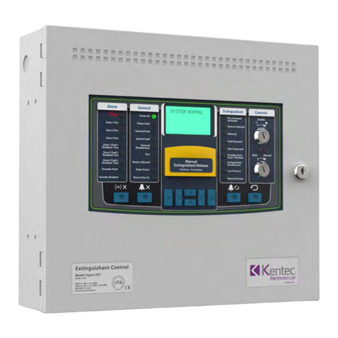
Kentec Electronics Sigma ZXT User manual

Man-1451 Rev.03
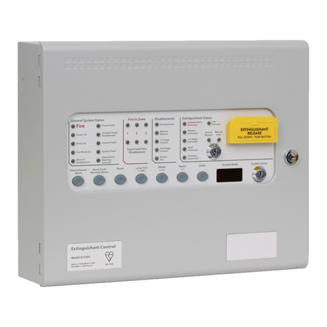
Extinguishant Release Panel
Sigma ZXT
Installation Manual
*Man-1451*

Man-1451 Rev.03
Safety
Suppliers of articles for use at work are required under section 6 of the Health and Safety at Work Act 1974 to ensure
as reasonably as is practical that the article will be safe and without risk to health when properly used.
An article is not regarded as properly used if it is used ‘without regard to any relevant information or advice’ relating
to its use made available by the supplier.
This product should be installed, commissioned and maintained by trained service personnel in accordance with the
following:
(i) Regulations for electrical equipment in buildings specific to the country of use.
(ii) Codes of practice
(iii) Statutory requirements
(iv) Any instructions advised by the manufacturer.
According to the provisions of the Act you are therefore requested to take such steps as are necessary to ensure
that you make any appropriate information about this product available to anyone concerned with its use.
Suppliers of articles for use at work are required under section 6 of the Health and Safety at Work Act 1974 to ensure
as reasonably as is practical that the article will be safe and without risk to health when properly used.
An article is not regarded as properly used if it is used ‘without regard to any relevant information or advice’ relating
to its use made available by the supplier.
This product should be installed, commissioned and maintained by trained service personnel in accordance with the
following:
(i) IEE regulations for electrical equipment in buildings
(ii) Codes of practice
(iii) Statutory requirements
(iv) Any instructions specifically advised by the manufacturer
According to the provisions of the Act you are therefore requested to take such steps as are necessary to ensure
that you make any appropriate information about this product available to anyone concerned with its use.
This equipment is designed to operate at 230V AC 50/60Hz mains supplies, class 1 construction. As such it must
be connected to a protective earthing conductor in the fixed wiring of the installation and a readily accessible double
pole disconnect device meeting the requirements of EN60950/IEC950 which disconnects live and neutral simulta-
neously shall be incorporated in the fixed wiring.
Switch disconnect devices such as MK Sentry 63A or similar are suitable for this. Failure to ensure that all conduc-
tive accessible parts of this equipment are adequately bonded to the protective earth will render the equipment un-
safe.
This Control Panel is environmental class A and is designed for indoor use only at temperatures between -10°C and
+45°C with a maximum relative humidity of 95%. The IP rating for the enclosure is IP30.
Operation outside of these limits may render the equipment unsafe.

Man-1451 Rev.03
Compliance
Sigma ZXT is compliant with the following standards:
EN54-2 and EN54-4 Fire Detection and Fire Alarm Systems - Control and Indicating Equipment
In addition to the standard EN54-2 requirements the following options with requirements have been includ-
ed in the Control Panel:
Output to alarm devices to enable an audible warning to be sounded throughout the premises upon the detection of
a fire condition or the operation of a manual call point. EN54-2 Section 7.8.
Test condition to allow the automatic resetting of zones in alarm for testing purposes. EN54-2 Section 10.
Delay of the actioning of fire alarm devices (sounders) so that an alarm may be verified before a premise is evacu-
ated. EN54-2 Section 7.11
In addition to the requirements of EN54-2, Sigma ZXT Control Panels have a voltage free relay contact for fire which
operates upon a fire condition. This is to be used for local control and signalling.
EN12094-1 Fixed fire-fighting systems - Components for gas extinguishing systems - Part 1: Requirements and test
methods for electrical automatic control and delay devices.
In addition to the standard EN12094-1 requirements the following options with requirements have been in-
cluded in the Control Panel:
EN12094-1 Section 4.17. Delay of extinguishing signal of up to 60 seconds.
EN12094-1 Section 4.18. Signal representing the flow of extinguishing agent to indicate the released condition.
EN12094-1 Section 4.19. Monitoring of the status of components by way of a low pressure switch input.
EN12094-1 Section 4.20. Emergency hold device to enable the extinguishant delay time to be extended.
EN12094-1 Section 4.21. Control of flooding time to deactivate the releasing output after a set period of time.
EN12094-1 Section 4.23. Manual only mode to disable the release of extinguishant via automatic detection devices.
EN12094-1 Section 4.25. Extinguishing signals to spare cylinders enables the switching to a spare set of cylinders
following a discharge to return the system to a functional state.
EN12094-1 Section 4.27. Emergency Abort device to inhibit the extinguishing signal until the emergency abort de-
vice has been de-activated and the Panel has been reset.
EN12094-1 Section 4.30. Activation of alarm devices with different signals to indicate pre-discharge and released
warnings using different sounds.
Default panel settings provide EN54-2 compliance:
BUZZER O/P: Enabled/Disabled This must be set to ENABLED.
MAINS FLT RLY DLY: OFF/30m This must be set to OFF.
FAULT RELAY: ENABLED/DISABLED This must be set to ENABLED.
FIRE RELAY: ENABLED/DISABLED. This must be set to ENABLED.
EARTH FAULT: ENABLED/DISABLED This must be set to ENABLED.
Important! Any deviation from these settings and compliance EN54-2 is void.

Man-1451 Rev.03
Disclaimer
In no event shall The Manufacturer be liable for any damages or injury of any nature or kind, no matter how caused,
that arise from the use of the equipment referred to in this manual. Strict compliance with the safety procedures set
out and referred to in this manual, and extreme care in the handling or use of the equipment, are essential to avoid
or minimise the chance of personal injury or damage to the equipment.
The information, figures, illustrations, tables, specifications, and schematics contained in this manual are believed
to be correct and accurate as at the date of publication or revision. However, no representation or warranty with re-
spect to such correctness or accuracy is given or implied and The Manufacturer will not, under any circumstances,
be liable to any person or corporation for any loss or damages incurred in connection with the use of this manual.
The information, figures, illustrations, tables, specifications, and schematics contained in this manual are subject to
change without notice.
Unauthorised modifications to the fire detection system or its installation are not permitted, as these may give rise
to unacceptable health and safety hazards.
By installing this equipment on a computer network, the owner accepts full and unequivocal responsibility for ensur-
ing that it is protected against all cyber threats and illegal tampering during the lifetime of the equipment. Any soft-
ware forming part of this equipment should be used only for the purposes for which The Company supplied it. The
user shall undertake no changes, modifications, conversions, translations into another computer language, or cop-
ies (except for a necessary backup copy).In no event shall The Manufacturer be liable for any equipment malfunction
or damages whatsoever, including (without limitation) incidental, direct, indirect, special, and consequential damag-
es, damages for loss of business profits, business interruption, loss of business information, or other pecuniary loss,
resulting from any violation of the above prohibitions.

Contents i
Man-1451 Rev.03
Sigma ZXT Product Manual
Section 1
Introduction ...................................................................................................................... 1
Section 2
Overview ........................................................................................................................... 2
Section 3
Panel Installation .............................................................................................................. 6
Before You Begin ............................................................................................................................................6
Installation checklist ........................................................................................................................................6
Fascia Panel/PCB Assembly Removal ...........................................................................................................7
Mounting the Panel .........................................................................................................................................9
Control Panel Fascia Wiring ............................................................................................................................11
Electrical Connections .....................................................................................................................................12
Enclosure Earth ...............................................................................................................................................12
Power Supply ..................................................................................................................................................13
Input Circuits ...................................................................................................................................................13
Detection Circuits .........................................................................................................................................13
BS5839 Detector removal ............................................................................................................................14
Intrinsically Safe (I.S.) Detection Zones .......................................................................................................14
Monitored Inputs .............................................................................................................................................15
Non-Monitored Inputs ......................................................................................................................................17
P1 & P2 Prog I/P’s ........................................................................................................................................17
Output Circuits ................................................................................................................................................18
Sounder circuits ............................................................................................................................................18
Extinguishing Outputs .....................................................................................................................................19
Operating of Dual Extinguishing Outputs ..................................................................................................... 19
Solenoid Wiring ...............................................................................................................................................20
Igniting Actuator Wiring ...................................................................................................................................20
Relay Outputs .................................................................................................................................................21
AUX 24V DC Supply .......................................................................................................................................22
RS485 Output .................................................................................................................................................22
Section 4
Controls ............................................................................................................................. 23
Control Panel Fascia .......................................................................................................................................23
Alarm status .................................................................................................................................................23
General status ..............................................................................................................................................23
Extinguishant status .....................................................................................................................................23
LED Indications ...............................................................................................................................................24
Alarm Status Indications ...............................................................................................................................24
General Status Indications ...........................................................................................................................25
Extinguishing Status Indications ...................................................................................................................26
Liquid Crystal Display (LCD) Indications .........................................................................................................28
Dynamic Displays .........................................................................................................................................28
User Controls ..................................................................................................................................................31
LCD Navigation Push Button ........................................................................................................................31
Silence Buzzer .............................................................................................................................................31
Silence Alarm ...............................................................................................................................................31
Alarm Re-sound ...........................................................................................................................................32
Reset ............................................................................................................................................................32
Manual Release ...........................................................................................................................................32
Control Key-Switches ...................................................................................................................................33
Internal Indicators and Controls ......................................................................................................................34
Watchdog Reset ...........................................................................................................................................34
Processor Reset ...........................................................................................................................................34
Term. Exting. (Terminate Extinguishing) ......................................................................................................34
Memory Lock ................................................................................................................................................34

Contents ii
Man-1451 Rev.03
Sigma ZXT Product Manual
Section 5
Panel Configuration ......................................................................................................... 35
Access Levels .................................................................................................................................................35
Access Level 1 .............................................................................................................................................35
Access Level 2 .............................................................................................................................................36
Access Level 3 (Engineering) .......................................................................................................................41
Connection to LE2 ...........................................................................................................................................53
Section 6
Adding/Removing Status Indicators & Ancillary Boards ............................................. 54
Adding a Status Unit to a ZXT .........................................................................................................................54
Removing a Status Indicator ...........................................................................................................................57
Adding an Ancillary Board to a ZXT ................................................................................................................58
Removing an Ancillary Board ..........................................................................................................................60
Section 7
Maintenance & Assistance .............................................................................................. 61
If You Need Help .............................................................................................................................................61
Limited Returns and Repairs Policy ................................................................................................................61
In-Warranty Items .........................................................................................................................................61
Damaged Goods ..........................................................................................................................................61
Component Failure .......................................................................................................................................61
Service Replacement Items .........................................................................................................................61
Repair Warranties ........................................................................................................................................62
Out Of Warranty Items .................................................................................................................................62
Customer Repairs ........................................................................................................................................62
Section 7
LCD Menu Structure ......................................................................................................... 63
Appendix A
Specification ..................................................................................................................... 67
Mechanical ......................................................................................................................................................67
Electrical ..........................................................................................................................................................67
Environmental .................................................................................................................................................70
Battery Calculation ..........................................................................................................................................71
Appendix B
Glossary ............................................................................................................................ 72

Introduction 1
Man-1451 Rev.03
Sigma ZXT Product Manual
1
Section 1
Introduction
Sigma ZXT is an advanced Extinguishing Control Panel designed for monitoring and control of gaseous fire sup-
pression systems.
Flexible and easy to use, clear status information is provided using a combination of LED’s and Liquid Crystal Dis-
play (LCD). The LCD also provides access to configuration menus enabling easy set-up as well as Event Log infor-
mation.
Three conventional detection zones provide the alarm stimulus required to activate the release of extinguishant. Any
single zone or combination of multiple zones, can be configured to contribute to the release of extinguishant.
Programmable volt-free relay outputs are provided which enable remote status signalling to other equipment.
Sigma ZXT functionality can be expanded by the addition of up to 7 Status Indicator Units providing remote indica-
tion and controls and up to 7 Ancillary Boards providing additional status outputs.

Overview 2
Man-1451 Rev.03
Sigma ZXT Product Manual
2
Section 2
Overview
The figure below provides an overview Sigma ZXT Panel hardware.
Figure 2-1
Compact Panel Features
1. Panel enclosure 11. LCD navigation push buttons
2. Control Panel fascia 12. Enter push-button
3. Alarm status LED indicators 13. Alarm Re-Sound push-button
4. General status LED indicators 14. Reset push-button
5. Liquid Crystal Display (LCD) 15. Manual Release push-button with protective cover
6. Extinguishant status LED indicators 16. Panel enclosure lock
7. Control key-switches
8. Silence buzzer push button
9. Alarm push button
10. Lamp Test and menu exit push-button
Reserve Selected
Released
Abort Operated
Hold Operated
Pre-activated/
Activated
Low Pressure
Flooding Zone
Fault / Disabled
Extinguishant
Disablement
Power On
Zone 1 Fire
Zone 2 Fire
Zone 3 Fire
Test
Buzzer Silenced
General
Disablement
Delay Active
General Fault
Power Fault
System Fault
Zone 1 Fault /
Disabled / Test
Zone 2 Fault /
Disabled/ Test
Zone 3 Fault /
Disabled / Test
Sounder Fault
Sounder Disabled
Auto Manual
Enable
Extract Fan On Manual Release
Alarm General
Extinguishant
Controls
1
16
5
2
4 6 73
8 9 10 11 12 13 14
15

Overview 2
Man-1451 Rev.03
Sigma ZXT Product Manual
3
Figure 2-2
Compact Panel Internal Features
1. Standby batteries (x2) 7. Enclosure fixing point (x3)
2. Controls Panel fascia fixings (x2) 8. 2.6A Power supply
3. Enclosure hinge points (x2) 9. Mini USB connection
4. Enclosure back-box 10. Memory lock toggle switch
5. Enclosure cable entry points (knock-outs) 11. Reset micro-switches
6. Control Panel wiring terminals
XMP201TAUK
E
24V DC
RELEASERELAY RELAY
MAN.S3FIRE
CNO
RELEASED
CNO
MODE
CNO
HOLD
CNO
ABORT
CNO
HOLD ABORT MODE
SWITCH
REL PRES.
SWITCH
LOW PRES. LCK OFF EXTING. RS485 AUX24
FAULT
NO C NC
PROG I/P
0VP2
P1
ZONE 3ZONE 1 ZONE 2 S2S1
Term.Exting.Processor ResetW/Dog Reset Memory Lock
O On
WARNING:
DO NOT PLUG OR UNPLUG RIBBON CABLES WHILE BOARD IS POWERED.
THIS SYSTEM CONTAINS STATIC SENSITIVE DEVICES. TO AVOID DAMAGE,
INSERTION OR REMOVAL OF CONNECTORS OR CIRCUIT BOARDS SHOULD
BE DONE WITH MAIN AND BACK UP POWER OFF.
Reserve Selected
Released
Abort Operated
Hold Operated
Pre-activated/
Activated
Low Pressure
Flooding Zone
Fault / Disabled
Extinguishant
Disablement
Power On
Zone 1 Fire
Zone 2 Fire
Zone 3 Fire
Test
Buzzer Silenced
General
Disablement
Delay Active
General Fault
Power Fault
System Fault
Zone 1 Fault /
Disabled / Test
Zone 2 Fault /
Disabled/ Test
Zone 3 Fault /
Disabled / Test
Sounder Fault
Sounder Disabled
Auto Manual
Enable
Extract Fan On Manual Release
Extinguishant Release
Manual
Pull Down - Push Button
Alarm General
Extinguishant
Controls
3
2
1
4 5 7 86
9
10
11

Overview 2
Man-1451 Rev.03
Sigma ZXT Product Manual
4
Figure 2-3
Large Panel Fascia Features
1. Panel enclosure 11. LCD navigation push-buttons
2. Controls Panel fascia 12. Enter push-button
3. Alarm status LED indicators 13. Alarm Re-Sound push button
4. General status LED Indicators 14. Reset push-button
5. Liquid Crystal Display (LCD) 15. Manual Release
6. Extinguishant status LED indicators 16. Panel enclosure lock
7. Control key-switches
8. Silence buzzer push-button
9. Silence Alarm button
10. Lamp Test and menu exit push-button
Reserve Selected
Released
Abort Operated
Hold Operated
Pre-activated/
Activated
Low Pressure
Flooding Zone
Fault / Disabled
Extinguishant
Disablement
Power On
Zone 1 Fire
Zone 2 Fire
Zone 3 Fire
Test
Buzzer Silenced
General
Disablement
Delay Active
General Fault
Power Fault
System Fault
Zone 1 Fault /
Disabled / Test
Zone 2 Fault /
Disabled/ Test
Zone 3 Fault /
Disabled / Test
Sounder Fault
Sounder Disabled
Auto Manual
Enable
Extract Fan On Manual Release
Alarm General
Extinguishant
Controls
1
16
5
2
4 6 73
8 9 10 11 12 13 14
15

Overview 2
Man-1451 Rev.03
Sigma ZXT Product Manual
5
Figure 2-4
Large Panel internal layout
1. Standby batteries (x2) 7. Enclosure fixing point (x3)
2. Controls Panel fascia fixings (x2) 8. 5.25A Power supply (behind controls fascia)
3. Enclosure hinge points (x2) 9. Mini USB connection
4. Enclosure back-box 10. Memory lock toggle switch
5. Enclosure cable entry points (knock-outs) 11. Reset micro-switches
6. Control Panel wiring terminals
3
2
1
4 5 7 86
9
10
11
XMP201TAUK
E
24V DC
RELEASERELAY RELAY
MAN.S3FIRE
CNO
RELEASED
CNO
MODE
CNO
HOLD
CNO
ABORT
CNO
HOLD ABORT MODE
SWITCH
REL PRES.
SWITCH
LOW PRES. DIS EXTG EXTING. RS485 AUX24
FAULT
NO C NC
PROG I/P
0VP2
P1
ZONE 3ZONE 1 ZONE 2 S2S1
Term.Exting.Processor ResetW/Dog Reset Memory Lock
O On
WARNING:
DO NOT PLUG OR UNPLUG RIBBON CABLES WHILE BOARD IS POWERED.
THIS SYSTEM CONTAINS STATIC SENSITIVE DEVICES. TO AVOID DAMAGE,
INSERTION OR REMOVAL OF CONNECTORS OR CIRCUIT BOARDS SHOULD
BE DONE WITH MAIN AND BACK UP POWER OFF.
Reserve Selected
Released
Abort Operated
Hold Operated
Pre-activated/
Activated
Low Pressure
Flooding Zone
Fault / Disabled
Extinguishant
Disablement
Power On
Zone 1 Fire
Zone 2 Fire
Zone 3 Fire
Test
Buzzer Silenced
General
Disablement
Delay Active
General Fault
Power Fault
System Fault
Zone 1 Fault /
Disabled / Test
Zone 2 Fault /
Disabled/ Test
Zone 3 Fault /
Disabled / Test
Sounder Fault
Sounder Disabled
Auto Manual
Enable
Extract Fan On Manual Release
Alarm General
Extinguishant
Controls
Extinguishant Release
Manual
Pull Down - Push Button

Panel Installation 3
Man-1451 Rev.03
Sigma ZXT Product Manual
6
Section 3
Panel Installation
This section describes the installation process.
Before You Begin
Before you begin the installation, take time to review the installation information, gather the required items and com-
plete the tasks listed below.
CAUTION!
• Create a plan and checklist before starting the installation process.
• Select an environment that is suitable for operating the Control Panel. The site chosen for mounting the Control
Panel should be clean, dry, flat and not subject to excessive shock, vibration or heat. Ensure after the installa-
tion the Control Panel enclosure is free from any debris.
• Verify the following items are present:
Installation checklist
The installation must be performed by qualified personnel familiar with electronic components. Electronic
components within the Control Panel are vulnerable to damage from electronic discharge. Ground straps
must be worn by installers before handling circuit boards to prevent damage from electronic discharge.
Item Quantity Description
Enclosure 1
Mild steel enclosure comprising of lid, back-box, hinge pins, label plates, Panel lock.
Control Panel 1 Control Panel assembly (fascia plate) complete with printed circuit board (PCB).
Power supply 1 2.6A or 5.25A power supply.
Earth connections 1
Green/yellow earth wires fitted with spade connectors, between enclose lid and back-box.
Standby battery leads 1 For connecting standby batteries.
Quick Start Guide 1 Essential Setup information and gateway to Product Manual.
End of line diodes 4 Fitted to sounder and solenoid circuits for monitoring
Battery leads 1 Used to connect standby batteries.
Keys 4 2x enclosure lock, 2x enable controls.
End of line resistors 10 Fitted to monitored input terminals for monitoring.
Create an installation plan and checklist.
Remove the Panel from its packaging and check the contents.
Remove the Control Panel fascia/PCB assembly.
Mount the enclosure to the premises wall using appropriate fixings.
Refit Control Panel fascia/PCB assembly.
Thread external cabling into the enclosure and make connections to Control Panel terminals.
Place standby batteries in base of enclosure and make connections.
Apply mains power.
Configure.
Test installation.

Panel Installation 3
Man-1451 Rev.03
Sigma ZXT Product Manual
7
Fascia Panel/PCB Assembly Removal
To assist the installation it is recommended that the Control Panel fascia is removed, this prevents potential damage
and provides additional working space.
Steps to remove fascia plate:
Important! For safety reasons mains power must be disconnected before attempting to remove the fascia plate.
1.Disconnect the DC supply to the fascia PCB by removing the pluggable connector mounted as shown in figure 3-1
Figure 3-1
Disconnect DC Supply
2.Disconnect the 14-way PSU monitoring ribbon cable from the Fascia PCB as shown in figure 3-2.
Figure 3-2
Disconnect 14-Way Cable
1
2

Panel Installation 3
Man-1451 Rev.03
Sigma ZXT Product Manual
8
3.Locate the two screws securing the fascia plate to the enclosure. Loosen the screws enough to allow the fascia
plate to be removed as shown in fig 3-3.
Figure 3-3
Remove Fascia Plate
4.Store the fascia plate in safe location until required.
5.To refit the fascia plate follow steps 1 to 3 in reverse.
12
3
1

Panel Installation 3
Man-1451 Rev.03
Sigma ZXT Product Manual
9
Mounting the Panel
The control panel should be located in an accessible place as agreed with the end user.
Mounting should be at a height suitable for viewing status displays and operation of controls. Mounting surfaces
should be clean, dry and flat, uneven mounting surfaces can cause distortion of the enclosure and internal PCBs
leading to problems.
5mm screws or bolts should be used along with suitable wall plugs to secure the control panel to the wall.
Control panels should not be mounted inside other enclosures, near sources of excessive heat or close to any ca-
bles or equipment of high voltage or high frequencies.
External cabling should enter the control panel through suitable cable glands fitted in the knock-outs provided.
Note: Enclosures vary. Figure 3-4 and Figure 3-5 show enclosure back box dimensions and fixing centres.
Figure 3-4
XM2 Back Box Dimensions (mm). Drawing Not to Scale.
365.8
315.8
29.0
319.6
262.1

Panel Installation 3
Man-1451 Rev.03
Sigma ZXT Product Manual
10
Figure 3-5
XM3 Back Box Dimensions (mm) Drawing Not to Scale.
365.8
315.8
29.0
428.6
374.6

Panel Installation 3
Man-1451 Rev.03
Sigma ZXT Product Manual
11
Control Panel Fascia Wiring
Shielded fire alarm cable such as FP200 and metal cable glands must be used for all circuits connected to the Panel,
the resistance of any core of the cable must not exceed 25 Ohms.
Fire alarm cables must be bonded securely to the enclosure via a metal cable gland.
Multiple size knock-out cable entries are provided in the top of the enclosure back box (12 x M20, 2 x M22) and
where possible wiring should enter the enclosure using these knock-outs. Cables should be formed tidily to the ap-
propriate terminals leaving only enough wire to ensure that there is no strain on the PCB.
Wiring must not go across the front of the circuit board plate or between the plate and the circuit board.
Figure 3-6
Wiring practice
INCORRECT
CORRECT
INCORRECT
::
;

Panel Installation 3
Man-1451 Rev.03
Sigma ZXT Product Manual
12
Electrical Connections
All connections for field wiring are to a single row of screw terminals along the top of the Control Panel circuit board.
Figure 3-7
Screw Terminals
The table below shows terminal designations.
Enclosure Earth
Important! To maintain continuity of Earth, a wire is provided connected between the enclosure earth terminal block
(found on the inside rear of the enclosure back-box) and mains Earth.
This connection must be maintained and in place prior to panel operation.
Terminal
No.
Function Connec-
tion
Terminal
No.
Function Connec-
tion
Terminal Function Connec-
tion.
TP1
ZONE 1
(+) TP19
HOLD
NO TP37 REL
PRES.
SWITCH
(+)
TP2 (-) TP20 C TP38 (-)
TP3
ZONE 2
(+) TP21
ABORT
NO TP39 LOW
PRES.
SWITCH
(+)
TP4 (-) TP22 C TP40 (-)
TP5
ZONE 3
(+) TP23
S1
(+) TP41
DIS EXTG
(+)
TP6 (-) TP24 (-) TP42 (-)
TP7
PROG I/P
P1 TP25
S2
(+) TP43
EXTING.
(+)
TP8 P2 TP26 (-) TP44 (-)
TP9 0V TP27
S3
(+) TP45
RS485
(+)
TP10
FAULT
RELAY
NO TP28 (-) TP46 (-)
TP11 C TP29
HOLD
(+) TP47
AUX 24
(+)
TP12 NC TP30 (-) TP48 (-)
TP13 FIRE
RELAY
NO TP31
ABORT
(+)
TP14 C TP32 (-)
TP15
RELEASED
NO TP33 MAN
RELEASE
(+)
TP16 C TP34 (-) TP60
24V DC
(+)
TP17 MODE NO TP35
MODE
(+) E
TP18 C TP36 (-) (-)
RELEASE
RELAY RELAY
MAN.
S3
FIRE
CNO
RELEASED
CNO
MODE
CNO
HOLD
CNO
ABORT
CNO
HOLD ABORT MODE
SWITCH
REL PRES.
SWITCH
LOW PRES. DIS EXTG EXTING. RS485 AUX24
FAULT
NO C NC
PROG I/P
0V
P2
P1
ZONE 3ZONE 1 ZONE 2 S2S1

Panel Installation 3
Man-1451 Rev.03
Sigma ZXT Product Manual
13
Power Supply
Sigma ZXT has two power supply options (specified at time of purchase):
Either version provides power for the main PCB as well as monitoring and charging of back-up batteries.
The DC output of the power supply is connected to a pluggable terminal block located in the upper right of the main
PCB. The pluggable terminal facilitates the removal of the fascia plate/PCB assembly.
Important! Mains input to the power supply must be disconnected before removal of the pluggable terminal block.
Fault monitoring of the power supply is provided by an 14-way IDC cable harness between the power supply and the main
Panel PCB.
Sigma ZXT is offered in two enclosure versions. The XM2 version accommodates 2 x 7Ah SLA batteries. The XM3 version
can accommodate up to 2 x 18Ah SLA batteries.
Input Circuits
The Sigma ZXT is provided with various monitored and non-monitored input circuits, this sub-section provides details on
functionality and wiring for each of the inputs.
Detection Circuits
Three conventional detection circuits are provided for the connection of conventional type automatic detection de-
vices.
Each conventional detection zone circuit provides a nominal 21.3V DC (+/-0.1V) to power conventional Detectors.
Conventional detection zone circuit must be wired as a single, two core radial circuit monitored by means of a 6k8Ω
end of line (EOL) resistor. EOL monitoring resistors are supplied fitted in the Control Panels’ terminals and must be
removed and installed in the last device on the zone circuit.
The 6K8ΩEOL resistor should be left connected to the terminals of any unused zones.
The number of detection devices supported per zone will vary dependent on detector manufacturer. The current rat-
ing of the zone circuit and zone devices should be reviewed at system design stage.
To ensure compliance with circuit monitoring requirements no more than 32 devices should be fitted to one zone.
Figure 3-8
Detection Circuit Diagram
2.6A Power supply 5.25A Power supply
Input voltage 230V AC Input voltage 230V AC
Output voltage 20.3 - 28.3V DC Output voltage 19 - 28.5V DC
Power rating 2.6A Power rating 5.25A
Standby batteries (max.) 2 x 7Ah SLA Standby batteries (max.) 2 x 18Ah SLA
DETECTOR
+
-
+
IN OUT
IN OUT
-
ZONE
DETECTOR
+-
+
-
+
IN OUT
IN OUT
-
END OF LINE
RESITOR

Panel Installation 3
Man-1451 Rev.03
Sigma ZXT Product Manual
14
BS5839 Detector removal
Systems required to comply with BS5839 Part 1 detector removal requirements must be fitted with a 47uF capacitor
(provided in spares bag) across the zone terminals and an LCMU active end of line monitoring device at the end of
the zone in place of the end of line resistor. Detectors installed on the zone must use detector bases fitted with a
schottky diode, circuit wiring details are shown in fig 3-9.
Figure 3-9
BS5839 Part 1 Detector Removal Zone Wiring
Intrinsically Safe (I.S.) Detection Zones
Sigma ZXT supports the use of I.S. barriers for connecting to intrinsically safe detection devices installed within haz-
ardous areas.
Important! Only I.S. certified detectors may be installed within hazardous areas and must be connected to the ZXT
Control Panel through a compatible I.S. barrier - MTL5561.
Connection of the I.S. barrier changes the characteristics of the detection circuit, to enable correct monitoring of the
circuit the Panel zones must be configured for use with I.S. barriers (see the configuration section of this manual).
The number of detection devices that can be connected to an I.S. detection zone is limited by the I.S. approval sys-
tem diagram which should be supplied by the detector manufacturer. The power rating of the end of line resistor will
be dependent upon the Zone classification rating (Gas class) this will be specified on the system diagram.
Figure 3-10
Intrinsically Safe Detection Zone Diagram
For detection zone configuration, please go the Configuration section of this manual.
ZONE
DETECTOR
47μF CAPACITOR
+-
+
-
+
IN OUT
IN OUT
-
LCMU
Part No. K14060
SCHOTTKY DIODE
DETECTOR
+
-
+
IN OUT
IN OUT
-
ZONE
DETECTOR
HAZARDOUS AREASAFE AREA
MTL5561
+-
+
-
+
IN OUT
IN OUT
-
END OF LINE
RESITOR
+
-
+
-
Other manuals for Sigma ZXT
2
Table of contents
Other Kentec Electronics Control Panel manuals

Kentec Electronics
Kentec Electronics Syncro User manual

Kentec Electronics
Kentec Electronics Sigma ZXT User manual

Kentec Electronics
Kentec Electronics Syncro Focus User manual

Kentec Electronics
Kentec Electronics Solo 2 Lite Guide

Kentec Electronics
Kentec Electronics Sigma XT Plus User manual

Kentec Electronics
Kentec Electronics Taktis User manual

Kentec Electronics
Kentec Electronics Sigma XT+ User manual

Kentec Electronics
Kentec Electronics Sigma ZXT User manual

Kentec Electronics
Kentec Electronics Sigma CP K Series User manual

Kentec Electronics
Kentec Electronics Syncro ASM User manual