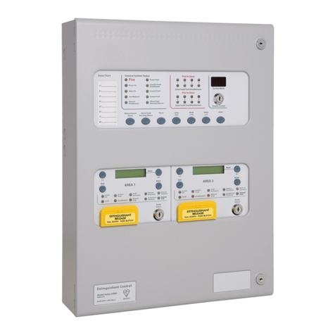
Kentec Electronics Solo 2 Lite Guide

Issue A April 2002
Solo 2 Lite
Single Loop
Analogue Addressable
Fire Control Panel
Installation
Commissioning
& Operating Manual
Issue
A April 2002

Issue A April 2002
2

Issue A April 2002
3
Contents
1. INTRODUCTION .............................................................................................................. 5
2. SAFETY.......................................................................................................................... 6
3. INSTALLATION.............................................................................................................. 6
4. CABLING........................................................................................................................ 7
5. POWERING THE PANEL............................................................................................... 7
5.1 Starting the Panel for the first time ...............................................................................................7
5.2 Starting a panel that has already been configured....................................................................7
6. PROGRAMMING THE PANEL FROM THE P.C. APPLICATION.................................. 8
6.1 Auto Addressing Hochiki CHQ-BS Base Sounders...................................................................8
6.2 Transferring Configuration from PC to panel.............................................................................8
6.3 Configuration Error Messages.......................................................................................................9
6.3.1. Disconnected Device..................................................................................................................9
6.3.2 Unexpected Device......................................................................................................................9
6.3.3 Double Address............................................................................................................................9
6.4 Transferring Configuration from panel to PC .............................................................................9
6.5 File transfer options.......................................................................................................................10
7. CONFIGURING THE PANEL WITHOUT A P.C. .......................................................... 11
7.1 Adding devices to the system......................................................................................................11
7.2 Reconfigure the panel Automatically.........................................................................................11
7.3 Zone Allocation...............................................................................................................................11
7.4 Message Allocation........................................................................................................................12
7.5 Configuring Delays to Outputs....................................................................................................12
8. TESTING THE SYSTEM............................................................................................... 12
9. USING THE SOLO2LITE PANEL ................................................................................ 13
9.1 Front Panel Controls......................................................................................................................13
9.1.1 Access Level 1 Controls ................................................................................................................13
9.1.1.1 Silence Buzzer.................................................................................................................................................13
9.1.1.2 Lamp Test.........................................................................................................................................................13
9.1.1.3 More Events.....................................................................................................................................................13
9.1.2.Access Level 2 Controls ................................................................................................................13
9.1.2.1 Evacuate / Resound Alarm...........................................................................................................................13
9.1.2.2 Silence Alarms.................................................................................................................................................13
9.1.2.3 Reset..................................................................................................................................................................13
9.1.2.4 More Events –Menu Access........................................................................................................................14
9.2. Front Panel Indications.....................................................................................................................14
9.2.1 Fire Indicators................................................................................................................................14
9.2.2 Fault Indicators..............................................................................................................................14
9.2.2.1 General Fault ...................................................................................................................................................14
9.2.2.2 Power Fault ......................................................................................................................................................14
9.2.2.3 System Fault ....................................................................................................................................................14
9.2.2.4 Sounder Disabled............................................................................................................................................14
9.2.2.5 Sounder Fault...................................................................................................................................................14
9.2.3 Other Indicators.............................................................................................................................14
9.2.3.1 Power On..........................................................................................................................................................14
9.2.3.2 Pre-alarm..........................................................................................................................................................14
9.2.3.3 Sounder Silenced............................................................................................................................................14
9.2.3.4 On Test..............................................................................................................................................................14
9.2.3.5 Buzzer Silenced...............................................................................................................................................14
9.2.3.6 Delay Active......................................................................................................................................................14
9.2.3.7 More Events.....................................................................................................................................................15
9.2.3.8 General Disablement......................................................................................................................................15
9.3 Internal Indications.........................................................................................................................15
9.3.1 Watchdog Fault ............................................................................................................................. 15
Issue A April 2002
4
10. USER FACILITIES MENU –(ACCESSLEVEL 2) ..................................................... 16
10.1 Disablements.................................................................................................................................16
10.1.1 Enable / Disable Zones................................................................................................................16
10.1.2 Enable / Disable Addresses.........................................................................................................16
10.1.3 Disable Panel Outputs.................................................................................................................17
10.1.3.1 Enable / Disable Fire Contact....................................................................................................................17
10.1.3.2 Enable / Disable Fault Contact..................................................................................................................17
10.1.4 Enable / Disable Sounders............................................................................................................17
10.2 Test Zones.....................................................................................................................................17
10.3 Set the System Clock...................................................................................................................18
10.4 Contamination Status..................................................................................................................18
10.5 Enter Level 3 Password...............................................................................................................18
10.6 Quit Menu.......................................................................................................................................18
11. ENGINEERING FACILITIES MENU –(ACCESS LEVEL 3) ...................................... 19
11.1 Configuration.................................................................................................................................19
11.1.1 Configure Zones..........................................................................................................................19
11.1.2 Configure Messages....................................................................................................................19
11.2 Printing...........................................................................................................................................19
11.3 Configure Output Delays.............................................................................................................20
11.3.1 Configure Delay Time ..................................................................................................................20
11.3.2 Panel Sounder Delay...................................................................................................................20
11.3.3 Configure Device Alarm Delay.....................................................................................................20
11.4 Event Log.......................................................................................................................................20
11.4.1 View Events.................................................................................................................................20
11.4.2 Clear Event Register....................................................................................................................21
11.5 Access Level 2..............................................................................................................................21
12. SOUNDER OUTPUTS.................................................................................................... 21
12.1 Panel Sounder Outputs...............................................................................................................21
12.2. Loop Sounder Outputs...............................................................................................................22
13. RELAYS...................................................................................................................... 23
14. REMOTE CONTROL INPUTS .................................................................................... 23
14.1 FLT (Fault)......................................................................................................................................23
14.2 RES (Reset)....................................................................................................................................23
14.3 INT (Intermittent)...........................................................................................................................24
14.4 CNT (Continuous).........................................................................................................................24
14.5 SIL (Silence)...................................................................................................................................24
15. DETECTION CIRCUIT................................................................................................ 24
16. BATTERY CHARGER AND PSU............................................................................... 25
17. SYSTEM FUSE........................................................................................................... 26
18. EARTH FAULT MONITORING................................................................................... 26
19. WATCHDOG............................................................................................................... 26
20. CALIBRATION ........................................................................................................... 26
21. TECHNICAL SPECIFICATION ....................................................................................... 27
APPENDIX A. –SOLO2LITE PANEL RESTRICTIONS .................................................. 28
APPENDIX B. –EN54 CONFIGURATION REQUIREMENTS. ........................................ 29
APPENDIX C. –FIELD WIRING AND PCB DETAILS..................................................... 30

Issue A April 2002
5
1. Introduction
Solo2 Lite is an analogue addressable fire detection and alarm control panel capable of covering a maximum
of 16 zones with up to 127 individual Hochiki ESP or 126 Apollo S90 / XP95 / Discovery and XPlorer
communications protocol devices.
Solo2 Lite supports loop powered sounders. In the case of Hochiki CHQ-BS devices used as sensor bases,
the sounders do not occupy an address in the range 1-127 thus leaving these addresses free for other
devices.
Any number of devices can be allocated to any of the 16 zones, ensuring that any system configuration can
be easily accommodated.
To ensure that the system is installed and commissioned with the minimum of trouble, it should be carefully
planned before the installation is begun.
This involves allocating an address to each device (excluding Hochiki CHQ-BS base sounders) and
allocating a message of up to 40 characters (including spaces) to each address to assist in the location of
the devices.
Devices should then be grouped into zones in accordance with the appropriate fire detection systems design
standard.
A fire alarm call point should be located near the panel.
The Solo2 Lite control panel offers an extensive list of features and options for the control and monitoring of
plant, equipment and sounders, which can be configured via the PC configuration programme.
Hochiki ESP Protocol offers an addressing range from 1 to 127 and Apollo S90 / XP95 / XPlorer and
Discovery Protocol offers an addressing range of 1 to 126. However, some ancillary devices such as the
Hochiki CHQ-S (switch monitor) and CHQ-B (bell controller) or Apollo Switch Monitor and Zone Monitor have
"Sub-addresses" in addition to their main address.
Therefore a CHQ-S (switch monitor) for example, may have a main address of 123, input 1 sub-address at
address 123.1 and input 2 at address 123.2.
The sub-addresses can be treated as if they were individual addresses, and each can be allocated to any
zone, given an individual address message and be operated on by different cause and effect tables.
The control panel has the following options with requirements as defined in BS EN54-2 : 1999
1) Fault signals from points
2) Disablement of each address point
3) Test condition
4) Fire alarm devices (sounders)

Issue A April 2002
6
2. Safety
Suppliers of articles for use at work are required under section 6 of the Health and Safety at Work act 1974
to ensure as reasonably as is practical that the article will be safe and without risk to health when properly
used.
An article is not regarded as properly used if it is used 'without regard to any relevant information or advice'
relating to its use made available by the supplier.
This product should be installed, commissioned and maintained by trained service personnel.
(i) IEE regulations for electrical equipment in buildings
(ii) Codes of practice
(iii) Statutory requirements
(iv) Any instructions specifically advised by the manufacturer
According to the provisions of the Act you are therefore requested to take such steps as are necessary to
ensure that any appropriate information about this product is made available by you to anyone concerned
with its use.
This equipment is designed to be operated from 230V 50Hz mains supplies and is of class 1 construction.
As such it must be connected to a protective earthing conductor in the fixed wiring of the installation and a
readily accessible double pole disconnect device shall be incorporated in the fixed wiring.
Failure to ensure that all conductive accessible parts of this equipment are adequately bonded to the
protective earth will render the equipment unsafe.
Mains Transformer Technical Information
Type -6
Input -230V AC
Frequency -50/60 Hz
Power -100 VA
V Out -5, 14, 24 & 33V
3. Installation
Installation of the panel should be carried out by qualified personnel only.
The electronic components within the panel are vulnerable to physical damage and damage by electrostatic
discharges. It is advisable to wear a wrist strap designed to prevent the build-up of static charges within the
body, before handling any electronic circuit boards.
Never insert or remove boards or components with the power on.
Mounting the Cabinet
The site chosen for the location of the panel should be clean and dry and not subject to shock or vibration.
The temperature should be in the range 5° to 35° C, the humidity should not exceed 95%.
Open the cover using the key provided.
Using the chassis as a template, mark the position of the fixing holes, ensuring that the wall is flat at the
chosen location.
Drill and plug the wall then fix the cabinet using all fixings.
The polarity of the battery connection should be carefully checked before proceeding.

Issue A April 2002
7
4. Cabling
Cables should be brought into the cabinet using the knockouts provided and using couplers to maximise the
space within the enclosure.
Inlet bushings or cable glands should be used to maintain insulation.
The screen or drain wires should be bonded to the earth terminals provided.
The maximum size of cable, which can be terminated, is 2.5 mm.
The detection circuit communications protocol is highly immune to noise but sensible segregation from
known noise generating sources such as mains cables and florescent light fittings is recommended.
Detection circuit cable size and type is dependent on the number and type of devices used and should be
calculated for each installation.
Cabling for sounder circuits should be sized according to sounder load and cable length but 1.5mm should
suffice in the majority of cases.
The control panel requires a 230V AC supply, which should be derived from a separate fused spur, labelled
"Fire Alarm -Do Not Switch Off".
The mains supply must include an earth conductor connected to the fixed installation earthing system.
This equipment relies on the building installation for protection and requires a 5 amp protection device. The
mains supply should use cable with a minimum cross section of 1.5mm.
5. Powering the Panel
Ensure that the panel is free from swarf, wire ends, knockout discs and any other debris.
NOTE: The panel cannot be powered by the battery until the mains is first connected.
5.1 Starting the Panel for the first time
When supplied, the panel will contain no configuration information and when mains power is first applied the
display will show:
For about 7 seconds, followed by:
Or, if the "p(Evacuate)" or "q(Silence)" button is pressed once, the display will change to:
To select either of these, press the "uEnter (More Events)" button. It is usual to configure automatically at
this stage as this tells you exactly what the panel has found connected to the loop and this can then be
compared with what is expected.
At the "Configure Automatically" prompt press the "uEnter (More Events)" button to configure automatically,
the panel will display:
Turn on the switch (located at the top of the display PCB inside the panel enclosure) and wait for the
progress bar to fill the screen while the panel analyses the connected devices. After a couple of minutes the
panel will display:
(Where XXX is a 3-digit number representing the number of devices found).
Turn off the switch (located at the top of the display PCB) and the panel will now be running with all devices
allocated to zone 1.
5.2 Starting a panel that has already been configured
If the panel contains configuration data, it will always run with that configuration when powered up or reset
via the processor reset switch SW2 (see annex 3), as long as the write enable switch is in the OFF position.
SYSTEM INTEGRITY CHECK
CONFIGURATION MENU
Configure automatically
CONFIGURATION MENU
Configures from PC
AUTO CONFIGURATION
Turn memory write enable switch
XXX devices found
Turn off memory write enable switch

Issue A April 2002
8
6. Programming the Panel from the P.C. Application
If the system has been planned and the devices addressed carefully, commissioning the system using the
PC configuration utility should be simple and straightforward. The PC configuration utility has many benefits
over manual configuration such as defining cause and effect logic, rapid message allocation, suppliers name
entry, day / night mode setting and storage / retrieval of site data and is strongly recommended as the
preferred method of data entry.
6.1 Auto Addressing Hochiki CHQ-BS Base Sounders
If the system contains Hochiki CHQ-BS base sounders fitted above detection devices, then before a PC
configuration is sent to the panel, the panel must be configured automatically as described in section 5.1.
This will ensure that the panel addresses all CHQ-BS base sounders automatically. Sounders are allocated
an address that is 127 above the address of the sensor to which they are attached. Therefore a host sensor
at address 3 for example, would automatically address the CHQ-BS base sounder to address 130. Whilst the
CHQ-BS base sounder does not use one of the loop addresses in the range 1-127, it will still use one of the
200 total sub addresses permitted on the Solo2 Lite panel.
Once the automatic base sounder addressing has been done, the panel can be configured from the P.C.
6.2 Transferring Configuration from PC to panel
On the P.C. start the Solo configuration programme and open the required configuration data file.
Connect the special download lead to the serial port on the computer and to the connector J5 on the panel
(see annex 2 & 3). Ensure that the PC is set to communicate with the correct serial communications port
under the File-Options menu in the configuration program. This is usually COM 1 for most computers
NOTE: Sometimes the PC will produce an "earth fault" on the panel due to leakage currents. This can be
ignored, as it will clear as soon as the programming lead is removed.
On the Solo2Lite panel, turn the "Write Enable" switch (located at the top of the display PCB) to the “On”
position.
Restart the panel via the internal "Processor Reset" switch (see annex 2 & 3).
After the "System Integrity" check, the display will show:
Press the "q(Silence)" button -the display will change to:
Press the "uEnter (More Events)" button to select:
On the PC, select "send to panel" option from the toolbar buttons. The PC will display a progress bar
indicating each part of the configuration being sent. After the file has been transferred, the panel will display:
Turn off the memory write enable switch and the
panel will start "initialising". This process involves comparing the device configuration detected by the panel
from the detection circuit with the configuration transferred from the PC.
CONFIGURATION MENU
Reconfigure automatically
CONFIGURATION MENU
Reconfigure from PC
PC CONFIGURATION
Awaiting link, system not operational
CONFIGURATION COMPLETE
Turn off memory write enable switch

Issue A April 2002
9
If the two configurations match, and there is no field wiring or device problems the panel will display the time
and date and the suppliers name (if entered on the PC configuration program).
The system is now running normally and should be thoroughly tested to verify that all devices location and
zone references are correct and output device switching meets the system requirements.
6.3 Configuration Error Messages
If the configurations do not match, one or more fault messages will be displayed. These messages can be
used to reduce addressing errors on field devices as follows:
6.3.1. Disconnected Device
Indicates that this device was configured by the PC utility but was NOT found by the panel.
6.3.2 Unexpected Device
Indicates that this device was not configured by the PC utility but WAS found by the panel during
initialisation.
When both a Disconnected message and Unexpected message is shown, a reasonable assumption is that
the unexpected device should have the address shown by the disconnected fault.
6.3.3 Double Address
Indicates that more than one device has been set to the same address. There will probably be a
disconnected fault present on the system at the same time as a double address fault and this device is likely
to be the one incorrectly addressed.
6.4 Transferring Configuration from panel to PC
Before any work is undertaken on a previously configured Solo2 Lite panel, it is strongly recommended that
the site configuration information is backed up onto the P.C. using the following procedure.
On the P.C. start the Solo configuration programme and create a new configuration data file.
Connect the special download lead to the serial port on the computer and to the connector J5 on the panel
(see annex 2 & 3). It may be necessary to remove the ribbon lead to the panel printer (if fitted) to gain
access to this connector.
Ensure that the PC is set to communicate with the correct port under the File-Options menu in the
configuration program. This is usually COM 1 for most computers
NOTE: Sometimes the PC will produce an "earth fault" on the panel due to leakage currents. This can be
ignored as it will clear as soon as the programming lead is removed.
On the Solo2Lite panel, turn the "Write Enable" switch (located at the top of the display PCB) to the “On”
position.
Restart the panel via the internal "Processor Reset" switch (see annex 2 & 3).
After the "System Integrity" check, the display will show:
Press the "q(Silence)" button -the display will change to:
DISCONNECTED 002/002
Addr xxx.x zone xx (device type)
UNEXPECTED DEVICE 001/002
Addr xxx.x
DOUBLE ADDRESS 002/002
Addr xxx.x zone xx (device type)
CONFIGURATION MENU
Reconfigure automatically
CONFIGURATION MENU
Reconfigure from PC

Issue A April 2002
10
Press the "q(Silence)" button again -the display will change to:
Press the "uEnter (More Events)" button to select:
On the PC, select "get from panel" option from the toolbar buttons. The PC will display a progress bar
indicating each part of the configuration being sent.
After the file has been transferred, use the Save option on the P.C. to save the configuration to the P.C. disk
drive.
On the Solo2Lite panel, turn the "Write Enable" switch (located at the top of the display PCB) to the “Off”
position.
Restart the panel via the internal "Processor Reset" switch.
The system will initialise all devices with the stored configuration information.
6.5 File transfer options
If power is applied to the Solo2 Lite panel, or if it is restarted via Processor Reset SW2 with the "write enable"
switch in the “On” position, the panel will first perform an "integrity check" then display the configuration
menu options.
These 4 options can be viewed using the "p(Evacuate)" or "q(Silence)" buttons and selected using the "?
Enter (More Events)" button as follows:
Erases memory contents and stores all devices
found in zone 1. No location messages. Common
sounder operation.
Press -
"q(Silence)""p(Evacuate)"
Transfer previously created
configuration from PC to panel
"q(Silence)""?(Evacuate)"
Transfer current configuration
to PC for storage or editing
"q(Silence)""p(Evacuate)"
Make no changes
CONFIGURATION MENU
Reconfigure automatically
CONFIGURATION MENU
Reconfigure from PC
CONFIGURATION MENU
Transfer configuration to PC
CONFIGURATION MENU
Run with current configuration
PC CONFIGURATION
Awaiting link, system not operational
CONFIGURATION MENU
Transfer configuration to PC

Issue A April 2002
11
7. Configuring the panel without a P.C.
Limited configuration changes may be made to the system, by use of the front panel Engineering menu
options. These menu options permit the user to allocate zones and a 40-character message to device
addresses as well as setting delays to outputs. It is not possible to configure cause & effect, panel settings or
repeaters from the front of the panel.
In general, it is recommended that a P.C. is used to configure Solo2, Lite as this provides a backup copy of
the site details for reference purposes or the event of accidental loss of the panel configuration details.
7.1 Adding devices to the system
The Solo2 Lite panel does not permit the user to add devices to the system via the menu options. In a
previously configured system, when a new device is added the panel will show an Unexpected Device
warning message. To add this device to the panel configuration, it is recommended that a P.C. is used to
take a copy of the existing configuration, add the device to this configuration, then transfer the new
configuration back into the Solo2 Lite panel.
If there is no P.C. available, then the only option is to automatically configure the system (see Section 7.2),
then re-program all device location messages and zone information.
This is only possible for systems that do not have cause & effect information, repeaters or panel
details changed. This information can only be programmed using the P.C. configuration application.
7.2 Reconfigure the panel Automatically
Follow the procedure given in Section 5.1 (for a panel that has no previous configuration information). If the
panel has been previously configured, follow the procedure in Section 6.5, selecting the “Reconfigure
Automatically” menu option.
WARNING: Automatically configuring a Solo2Lite panel will erase ALL previous configuration
information. This may include Cause and Effect information, Repeater information and Panel details,
which cannot be restored without using a P.C. running the configuration application.
7.3 Zone Allocation
To allocate addresses to other zones without doing a download from a PC, it is necessary to enter the menu
list. To do this, insert the enable key and hold the "uEnter (More Events)" button until the display shows:
Press the "p(Evacuate)" button twice to view the Access Level 3 menu option. Press the "uEnter" button
to select this menu option. Use "p(Evacuate)" and "q(Silence)" to increment and decrement each
number. Use the "tExit" and "uEnter" move the cursor left and right. To enter the number (1000), press
and hold "uEnter " to enter the Access Level 3 menu options.
The display will then show:
Turn on the write enable switch. Located on top of the display PCB inside the panel.
The display will then show:
The actual address and device type will of course depend on what is connected at the lowest address on the
system.
DISABLEMENTS
DEVICE CONFIGURATION
Switch on write enable to view/change
CONFIGURE ZONE
Addr xxx.x CHQ-CP zone 1

Issue A April 2002
12
The available addresses and local programmable outputs can now be scrolled using the "p(Evacuate)" and
"q(Silence)" buttons to select the first address to be allocated. The zone number can be incremented using
the "uEnter" button, through the range 1 to 16. When Zone 16 is reached, pressing "uEnter" will set the
zone back to Zone 1. It is not possible to decrement the zone number.
Note: Base Sounders will automatically be allocated the same zone as the sensor to which they are
attached.
The information entered is stored dynamically i.e. it is not necessary to press the "uEnter" button to store
the information, it is stored as soon as the next address or zone is selected.
Press the "tExit" button to escape from the Zone allocation menu option.
7.4 Message Allocation
It is now possible to attach a 40-character message to each address if required.
This is done by pressing the "q(Silence)" button to view the "Configure Message" menu, then press "u
Enter". The display will show:
Letters, numbers and punctuation marks can now be selected using the Use "p(Evacuate)" and "q
(Silence)" buttons. Use the "tExit" and "uEnter" move the cursor left and right. This is repeated until the
message is complete.
To enter the message, press and hold "uEnter" button.
To enter the next message, it is necessary to go back to the Zone Allocation menu and select the required
address, then revert back to the message menu. The next message can now be entered as before. When
all zones and messages have been entered, the write enable switch must be turned off. The system is now
configured and will remember the programmed information, even if the power is removed.
7.5 Configuring Delays to Outputs
It is possible to set delays to panel and loop output devices. See section 11.3 for more details.
8. Testing the System
To ensure that the system operates as required it is first necessary to activate each device as shown on the
installation plan and ensure that the correct panel response and message is displayed.
Once this has been established as being correct, the zone and address configurations should be recorded
for future reference.
Next, the sounder outputs should be checked, making sure that they operate as required and that audibility
levels are acceptable. If any special sounder sequencing or control of output devices has been programmed,
all possible logical combinations should be checked to ensure that the required response is given.
Finally any use made of the volt free contacts or remote control inputs at the panel should be tested to
ensure that they operate as intended.
The system should then be ready for handover to the client who should be given a copy of the operator’s
manual, fire log book and a set of keys for accessing the panel.
EDIT TEXT ADDR XXX.X CHQ-CP
_ .

Issue A April 2002
13
9. Using the Solo2Lite Panel
Operation of the fire alarm system should be as simple and straightforward as possible. Solo2Lite maintains
this philosophy by utilising the minimum number of controls and highlighting the most important indications.
This ensures that a concise and unambiguous indication of the status of the system is presented to the user
at all times.
9.1 Front Panel Controls
There are 3 main controls required for the operation of the fire alarm system:
i) A means of sounding the alarms from the panel
ii) A means of silencing the alarms from the panel
iii) A means of resetting the alarms from the panel
All other functions associated with the essential requirements of the system are automatic and require no
user intervention.
Operation of all of the critical controls (with the exception of "Lamp Test" and "More Events") are inhibited in
accordance with EN54-2, until the controls are enabled by operation of the "Enable Controls" keyswitch.
9.1.1 Access Level 1 Controls
9.1.1.1 Silence Buzzer
Operation of the Silence Buzzer in the event of a fire or fault will:
i) Change the tone of the buzzer from continuous (or rapid pips for a fire event), to silent.
ii) Illuminate the "Buzzer Silenced" LED.
9.1.1.2 Lamp Test
Operation of the Lamp Test button will illuminate all front panel indicators for approximately 3 seconds.
9.1.1.3 More Events
If there is more than one event of any type on the panel (indicated by 002/002 or similar on the right of the
display and the "More Events" LED) then these can be viewed by pressing the "More Events" button to
advance through them.
9.1.2.Access Level 2 Controls
Operation of the enable control keyswitch will select access level 2. It is at this access level that the proper
functions of the controls are available.
9.1.2.1 Evacuate / Resound Alarm
Operation of the "Evacuate" button will now sound all sounders continuously whether connected to the
control panel loop or to field mounted bell controllers. To clear the panel from the Evacuate condition, press
the “Silence Alarms" button, followed by the "Reset" button.
9.1.2.2 Silence Alarms
Operation of the Silence Alarms button in the event of a fire will:
i) Change the tone of the fire buzzer from rapid pips, to one beep every 7 seconds.
ii) Change the flashing zonal fire indicator to continuous.
iii) Silence all sounders connected to the control panel and field mounted bell controllers.
iv) Illuminate the "Sounder Silenced" LED.
9.1.2.3 Reset
Operation of the "Reset" Button has no effect without prior operation of the "Silence Alarms” button following
a fire or evacuate condition.
Following operation of the "Silence Alarms" button during a fire condition, operation of the "Reset" button will
reset the fire condition at the control panel and reset the detector or detectors that initiated the fire condition.
If the fire condition was initiated by call points or switch input devices then these must be restored to normal
before "Reset" is operated otherwise the fire condition will return.

Issue A April 2002
14
9.1.2.4 More Events –Menu Access
When at Access level 2, press and hold the “More Events” button for three seconds to access the User
Facilities Menu.
9.2. Front Panel Indications
9.2.1 Fire Indicators
The primary indications on the control panel are those associated with the fire condition. A common fire
indicator will illuminate in the event of a fire detector, call point or input device being operated, accompanied
by one or more "Fire in Zone" indicators to identify the zone in which the fire originated.
The common fire indicator will also illuminate if the "Evacuate" button is pressed and will remain lit until the
condition is silenced then reset.
9.2.2 Fault Indicators
9.2.2.1 General Fault
The "General Fault" indicator will illuminate upon any fault condition. Additional information about the nature
of the fault can be obtained from the display or other fault indicators.
9.2.2.2 Power Fault
When there is a problem with either the main or standby supply the "Power Fault" LED will be illuminated in
addition to the General Fault LED. Additional information about the nature of the fault can be obtained from
the LCD status display
9.2.2.3 System Fault
The "System Fault" indicator will illuminate in the event of failure of execution of routines associated with the
main functions of the programme or corruption of the memory containing the programme or site configuration
data.
9.2.2.4 Sounder Disabled
Whenever the sounder outputs on the system are disabled the "Sounder Disabled" indicator will be
illuminated.
9.2.2.5 Sounder Fault
An open or short circuit on the cabling to the sounder circuits connected to the control panel will illuminate
the "Sounder Fault" indicator.
9.2.3 Other Indicators
9.2.3.1 Power On
Indicates that equipment is being supplied with power.
9.2.3.2 Pre-alarm
For sensors that are configured to report a pre-alarm, the "Pre-alarm" indicator will illuminate when the
control panel receives a signal from a sensor that is 85% of the set fire threshold level.
The panel buzzer will operate but no outputs will be operated during a pre-alarm condition.
9.2.3.3 Sounder Silenced
The "Sounder Silenced" indicator will be illuminated only when a fire condition has been silenced. Operation
of a subsequent fire condition whilst the alarms are silenced will extinguish the "Sounder Silenced" indicator.
9.2.3.4 On Test
The "On Test" indicator will be illuminated whilst any zones are in test mode.
9.2.3.5 Buzzer Silenced
The "Buzzer Silenced" indicator will indicate silencing of the buzzer during a fault, pre-alarm or fire condition.
9.2.3.6 Delay Active
It is possible to configure delays to outputs on the Solo2Lite the delay is active.

Issue A April 2002
15
9.2.3.7 More Events
The "More Events" indicator will be illuminated whenever there are events on the control panel that are not
currently displayed in the LCD status window. This would typically be seen in the situation where more than
one device is disabled or if there are multiple faults or fires on the system.
9.2.3.8 General Disablement
Any disablement selected via the menu functions or via cause & effect will be indicated by illumination of the
"General Disablement" indicator.
9.3 Internal Indications
9.3.1 Watchdog Fault
Operation of the panel is monitored by a "Watchdog" circuit, which will attempt to reset the central processor
unit in the event of a failure to execute the programme properly.
The “Watchdog Operated” LED (mounted inside the panel -See Fig. 1) indicates operation of the watchdog
circuit. This indicator will remain lit whether the reset was successful or not until it is reset using the
"Watchdog Reset" switch (See annex 3).

Issue A April 2002
16
10. User Facilities Menu –(Access Level 2)
A number of User Facilities are provided by a menu structure, which can only be accessed at Access Level
2.
To access the User Facilities menu, set the panel in to Access Level 2, using the Enable key. Press and hold
down the "uEnter (More Events)" button until the first menu item appears. The User Facilities menu takes
the form of a tree structure, where there are six main menu categories. These may be scrolled using the "p
(Evacuate)" and "q(Silence)" buttons. To select the required menu option, press the "uEnter (More
Events)" button. Some of the menu options have sub-categories, which are then scrolled using the "p
(Evacuate)" and "q(Silence)" buttons and selected using the "uEnter" button, and so on. To move back to
the main menu, press the "? Exit" button.
If no buttons are pressed for more than 100 seconds the panel will revert to access level 2 or if the key is
removed, to access level 1 (i.e. buttons not enabled).
The following describes each of the available facilities in the order that they will appear.
10.1 Disablements
10.1.1 Enable / Disable Zones
To disable one or more zones, first select the zone to be disabled using the "p(Evacuate)" and "q
(Silence)" buttons, then press "uEnter " to disable.
The display will show:
When a disablement is selected, the buzzer will sound a continuous tone for 3 seconds and the "General
Disablement" LED will light and remain lit for as long as there are any active disablements on the system.
Disablements will be displayed at access level 1 as follows:
Only fire inputs are suppressed during disablements. The "More Events" button can be used to view all
active disablements at access level 1. Zones can be re-enabled using the same procedure as for disabling.
10.1.2 Enable / Disable Addresses
To disable one or more addresses or sub-addresses, first select the address to be disabled using the "p
(Evacuate)" and "q(Silence)" buttons, then press "uEnter " to disable.
The display will show:
When a disablement is selected, the buzzer will sound a continuous tone for 3 seconds and the "General
Disablement" LED will light and remain lit for as long as there are any active disablements on the system.
Disablements will be displayed at access level 1 as follows:
If a location message has been assigned to the disabled address the second line of the display will alternate
between the address, zone and device type, and the message.
ENABLE / DISABLE ZONES
Zone XX is disabled
DISABLEMENT 001/001
ZONE 1
ENABLE / DISABLE ADDRESSES
Address xxx.x is disabled
DISABLEMENT 001/001
Addr xxx.x zone xx

Issue A April 2002
17
Only fire inputs are suppressed during disablements. The "More Events" button can be used to view all
active disablements at access level 1.
Addresses can be re-enabled using the same procedure as for disabling.
10.1.3 Disable Panel Outputs
This menu option has two sub-menu selections:
10.1.3.1 Enable / Disable Fire Contact
To disable the Fire Contact (labelled as Rem Sig inside the panel), press the "uEnter " button. The display
will show:
The disablement will be displayed at access level 1 as follows:
The Fire Contact (labelled as Rem Sig inside the panel) will not operate in response to any fire conditions
whilst disabled.
To re-enable the fire contact, use the same procedure as for disabling.
10.1.3.2 Enable / Disable Fault Contact
To disable the fault contact, press the "uEnter " button. The display will show:
The disablement will be displayed at access level 1 as follows:
The fault contact will not operate in response to any fault condition other than total power failure or system
fuse (F2) failure whilst disabled.
To re-enable the fault contact, use the same procedure as for disabling.
10.1.4 Enable / Disable Sounders
To disable the sounders, press the "uEnter " button.
The display will show:
The sounders connected to the panel, loop powered sounders and bell controller outputs (which are
programmed to respond as sounders) will not operate in response to any fire or evacuate condition.
To re-enable the sounders use the same procedure as for disabling.
10.2 Test Zones
To put one or more zones into test mode, select the required zone using the "p(Evacuate)" and "q
(Silence)" buttons to scroll to the desired zone number, then press "uEnter " button. The display will show:
ENABLE / DISABLE FIRE CONTACT
Fire contact is disabled
DISABLEMENT 001/001
Fire contact is disabled
ENABLE / DISABLE FAULT CONTACT
Fault contact is disabled
DISABLEMENT 001/001
Fault contact is disabled
ENABLE / DISABLE SOUNDERS
Sounders are disabled
TEST ZONES
Zone xx is in test mode

Issue A April 2002
18
When in test mode, activation of a device in the zone under test will cause a normal response at the control
panel and sound the sounders for 2 seconds. The control panel will then self-reset, ready for the next device
to be tested.
The Fire relay contact (labelled Rem.Sig) will not operate during test mode.
10.3 Set the System Clock
The panel contains a 24 hour clock which is battery backed.
To set the clock, use the "p(Evacuate)" and "q(Silence)" buttons to increment / decrement the hours then
press the "uEnter " button to move to the next item on the clock menu (minutes, day, year etc.).
When all clock parameters are correctly adjusted, press the "tExit" button to revert back to the menu.
When the panel is in normal condition at access level 1, the full time and date will be displayed on the top
row of the display.
10.4 Contamination Status
Any sensors that are found to be near their calibration limits are listed here. When a sensor is found to be at
or beyond 85% of the point at which a maintenance fault warning will be given, it is added to the list.
During the daily calibration routine, each sensors analogue levels are checked and if these are at or beyond
acceptable limits of compensation the status will be displayed as per the example below.
The lower line of the display will alternate between the information shown above and the location message
for the device.
Further devices on the list can be viewed by scrolling with the "p(Evacuate)" and "q(Silence)" buttons.
10.5 Enter Level 3 Password
This menu option is used to gain access to the Engineering Facilities Menu by entering the correct Access
Level 3 password (default setting for this password is 1000 for panels that have not been configured).
The password is entered using the "p(Evacuate)" and "q(Silence)" buttons to scroll through the numbers 0
to 9 and the "uEnter " button to move to the next digit. Press the "t?Exit" button to move the cursor to the
previous digit, if required. When the password has been entered, press and hold "uEnter " for 3 seconds.
The panel will display the first item on the Access Level 3 Engineering Facilities menu, upon successful entry
of the correct code.
It is possible (via the PC configuration programme) to change the password to any 4-digit number. If
entering the default password (1000) does not allow entry to the Access Level 3 menu, then this has been
done. If this occurs , it will be necessary to capture the configuration file from the panel using the "SOLO"
configuration package and data transfer lead.
10.6 Quit Menu
This is the last item in the User Facilities Menu and further presses of the "q(Silence)" button will
continually scroll around these 6 items.
Press the "uEnter " button to exit from the User Facilities Menu.
CONTAMINATION STATUS
Addr. 123 ALE-E ZP = 96% FP = 97%

Issue A April 2002
19
11. Engineering Facilities Menu –(Access Level 3)
To enter the Engineering Facilities Menu, select the Access Level 3 option in the User Facilities Menu. Enter
the password (factory set at 1000) using the "p(Evacuate)" and "q(Silence)" buttons, then press and hold
"uEnter" button.
11.1 Configuration
11.1.1 Configure Zones
If the panel has not been configured using the PC configuration package, all devices are placed in zone 1
upon initialisation. This menu allows any device or sub device to be configured to any of the 16 zones. Upon
activation of the "Write Enable" switch on the display PCB, the status display will show:
To change the zone number press the "uEnter " button until the required zone appears, then press the "p
(Evacuate)" and "q(Silence)" buttons to select the next address or Local Output (listed after the detection
devices). Repeat the procedure until all addresses have been configured in to the required zones.
11.1.2 Configure Messages
It is possible using the panel push buttons to enter text messages of up to 40 characters. Although this is
much better achieved using the PC configuration package, this facility does allow on site editing in situations
where a PC may not be available and to correct minor mistakes and site amendments.
From the configure zone menu, select the address for which the message is to be edited or allocated then
press "t? Exit". The display will show:
Press "q(Silence)":
Press the "uEnter " button:
In the bottom left of the display a cursor marks the position where the first character of the message will
appear. Upper and lower case letters, numbers from 0 to 9 and punctuation marks , . ( ) / can then be
selected using "p(Evacuate)" and "q(Silence)" buttons.
To move to the cursor left & right, press the "uEnter" and "t? Exit" buttons. To escape from the message
editing menu, press and hold the "uEnter" button.
To select other addresses for message entry or editing, it is necessary to select the address of the device
using the Edit Zones menu selection. Then follow the procedure above.
11.2 Printing
The Solo2Lite control panel is not available with a thermal printer option, and therefore all printer menu
commands are not applicable.
CONFIGURE ZONES
Addr 001.0 ATG-E zone 1
CONFIGURE ZONES
_
EDIT TEXT ADDR 001.0 ATG-E
_
CONFIGURE MESSAGES
_

Issue A April 2002
20
11.3 Configure Output Delays
It is possible to configure outputs to be delayed between 30 seconds and 10 minutes from the activation of a
smoke detection device. When an output is delayed, the Delay Active LED will be illuminated. The delay will
be cancelled by the activation of two devices or a single manual call point.
11.3.1 Configure Delay Time
There is a single delay time for all delayed outputs, which is configured as follows:
Use the "p(Evacuate)" and "q(Silence)" buttons to select the required delay time (30 seconds or 1 to 10
minutes in minute intervals) and then press "uEnter".
11.3.2 Panel Sounder Delay
The panel has two common conventional sounder circuits, which can be delayed to allow confirmation of a
fire condition if required. To enable the delay facility press the "uEnter" button when this screen is
displayed.
To disable the delay facility, press the "uEnter" button when this screen is displayed.
11.3.3 Configure Device Alarm Delay
The 24 local programmable outputs and the outputs of all addressable output devices are listed as follows:
Use the "p(Evacuate)" and "q(Silence)" buttons to scroll through all output addresses and local outputs.
Those outputs that are required to be delayed can be selected by pressing the "uEnter" button. The display
will then show:
11.4 Event Log
11.4.1 View Events
The system stores the last 100 events that have occurred. To view these press the "p(Evacuate)" and "q
(Silence)" buttons to scroll through the event log.
A typical event log display will show:
PANEL SOUNDER DELAY
Sounders not delayed
PANEL SOUNDER DELAY
Sounders delayed
CONFIGURE DEVICE ALARM DELAY
Address 003.1 is not delayed
CONFIGURE DEVICE ALARM DELAY
Address 003.1 is delayed
VIEW EVENTS-1 OF 25 26/01/01 11:21
System initialising
CONFIGURE DELAY TIME
30 seconds
Table of contents
Other Kentec Electronics Control Panel manuals

Kentec Electronics
Kentec Electronics Taktis User manual

Kentec Electronics
Kentec Electronics Sigma XT Plus User manual

Kentec Electronics
Kentec Electronics Syncro ASM User manual

Kentec Electronics
Kentec Electronics Syncro Focus User manual

Kentec Electronics
Kentec Electronics Taktis User manual

Kentec Electronics
Kentec Electronics Sigma CP K Series User manual

Kentec Electronics
Kentec Electronics Sigma XT K11031F2 User manual

Kentec Electronics
Kentec Electronics Sigma XT+ User manual

Kentec Electronics
Kentec Electronics Sigma ZXT User manual

Kentec Electronics
Kentec Electronics Syncro View Marine User manual