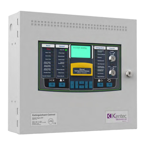
Kentec Electronics Sigma ZXT User manual

Man-1450EN Rev. 04
Sigma ZXT Quick Start Guide
Extinguishant Control Panel
Sigma ZXT
Quick Start Guide
*Man-1450EN*

Man-1450EN Rev. 04
Sigma ZXT Quick Start Guide
Safety
Suppliers of articles for use at work are required to ensure as reasonably as is practical that the article will be safe
and without risk to health when properly used. An article is not regarded as properly used if it is used 'without regard
to any relevant information or advice' relating to its use made available by the supplier.
This product should be installed, commissioned and maintained by trained service personnel in accordance with the
following:
(i) Regulations for electrical equipment in buildings specific to the country of use.
(ii) Codes of practice
(iii) Statutory requirements
(iv) Any instructions advised by the manufacturer.
Installers of this product are required to take such steps as necessary to ensure that all appropriate information and
training is provided to anyone concerned with its use.
This equipment is designed to operate at 230V AC 50/60Hz mains supplies, class 1 construction. As such it must
be connected to a protective earthing conductor in the fixed wiring of the installation, failure to ensure that all con-
ductive accessible parts of this equipment are adequately bonded to the protective earth will render the equipment
unsafe.
A readily accessible double pole disconnect device meeting the requirements of the relevant electrical safety regu-
lations specific to the country of use, which disconnects live and neutral simultaneously shall be incorporated in the
fixed wiring.
This equipment is certified as environmental class A and therefore designed for indoor use only at temperatures
between -10°C and +45°C with a maximum relative humidity of 95%. The IP rating for the enclosure is IP30.
Operation outside of these limits may render the equipment unsafe.

Sigma ZXT Quick Start Guide
Man-1450EN Rev. 04
Sigma ZXT Quick Start Guide
1
Sigma ZXT Quick Start Guide
This Quick Start Guide provides dedicatory information relating to standard and larger enclosure versions of the
Kentec Sigma ZXT Extinguishant Control Panel (ECP).
This Quick Start Guide covers:
• What’s in the box?
• QR Codes
• Panel at a Glance
• Connection Terminals
• Compliance
• Terms & Conditions
What’s in the box?
The Sigma ZXT includes the following components and hardware.
Figure A-1
Items in the box (NOT TO SCALE)
Important! Information in this Start Guide is supplementary.
The product Installation Manual and Operation Manual should read, understood and referred to throughout.
1x
Control
Panel
1x
Pre-mounted
Power Supply
2x
Enclosure
Lock Keys
4x
Key Switch
Keys
1x
Resistor,
Diode &
Capacitor Kit
1x
Power Supply
Accessory Pack
(Only supplied with
K195311XM3 and
K195312XM3)
1 x
Quick Start
Guide

Sigma ZXT Quick Start Guide
Man-1450EN Rev. 04
Sigma ZXT Quick Start Guide
2
QR Codes
The QR codes below provide links to the Sigma ZXT Installation and Operation Manuals. Using your Smartphone,
tablet or device (where necessary) install a third party QR Code Reader and scan the code to open the documents.
Figure A-2
Reading the QR Codes
Should you be unable to work with QR codes Manuals can be obtained by visiting the following website pages:
Installation Manual Operation Manual
Sigma ZXT Si Product Manual
Manual Variant Website
Installation Manual http://www.kentec.co.uk/manuals/man-1451EN.pdf
Operation Manual http://www.kentec.co.uk/manuals/man-1452EN.pdf
Sigma ZXT Si Product Manual http://www.kentec.co.uk/manuals/man-1453.pdf

Sigma ZXT Quick Start Guide
Man-1450EN Rev. 04
Sigma ZXT Quick Start Guide
3
Panel at a Glance
The diagrams below provide an overview of the panel main components and features:
Figure A-3
Sigma ZXT Front Fascia
1. Panel enclosure 9. Silence buzzer push button
2. Control Panel fascia 10. Alarm push button
3. Alarm Status LED indicators 11. Lamp test and menu exit push button
4. General Status LED Indicators 12. LCD navigation push buttons
5. Liquid Crystal Display (LCD) 13. Enter push button
6. Manual release push button with protective cover 14. Alarm Re-Sound push button
7. Extinguishant Status LED indicators 15. Reset push button
8. Control key-switches 16. Panel enclosure lock
15 7
16
2
910 11 13 15
3 4 8
12 14
6

Sigma ZXT Quick Start Guide
Man-1450EN Rev. 04
Sigma ZXT Quick Start Guide
4
Figure A-4
Sigma ZXT Standard Enclosure Internal Layout
1. Standby batteries (x2) 7. Enclosure fixing point (x3)
2. Controls Panel fascia fixings (x2) 8. Micro B USB connection
3. Enclosure hinge points (x2) 9. Memory lock toggle switch
4. Enclosure back-box 10. Reset micro-switches (x2)
5. Enclosure cable entry points (knock-outs) 11. Watchdog reset lamp
6. Control Panel wiring terminals 12. 2.6A Power supply (behind controls fascia)
E
24V DC
RELEASERELAY RELAY
MAN.S3FIRE
CNO
RELEASED
CNO
MODE
CNO
HOLD
CNO
ABORT
CNO
HOLD ABORT MODE
SWITCH
REL PRES.
SWITCH
LOW PRES. DIS EXTG EXTING. RS485 AUX24
FAULT
NOC
NC
PROG I/P
0VP2
P1
ZONE 3ZONE 1 ZONE 2 S2S1
Term.Exting.Processor ResetW/Dog Reset Memory Lock
OnO
1
2
3
4 5 6 7
8
9
10
12
11

Sigma ZXT Quick Start Guide
Man-1450EN Rev. 04
Sigma ZXT Quick Start Guide
5
Figure A-5
Sigma ZXT Large Enclosure Internal Layout
1. Standby batteries (x2) 7. Enclosure fixing point (x3)
2. Controls Panel fascia fixings (x2) 8. Micro B USB connection
3. Enclosure hinge points (x2) 9. Memory lock toggle switch
4. Enclosure back-box 10. Reset micro-switches (x2)
5. Enclosure cable entry points (knock-outs) 11. Watchdog reset lamp
6. Control Panel wiring terminals 12. 5.25A Power supply
8
9
10
12
11
E
24V DC
RELEASERELAY RELAY
MAN.S3FIRE
CNO
RELEASED
CNO
MODE
CNO
HOLD
CNO
ABORT
CNO
HOLD ABORT MODE
SWITCH
REL PRES.
SWITCH
LOW PRES. DIS EXTG EXTING. RS485 AUX24
FAULT
NOC
NC
PROG I/P
0VP2
P1
ZONE 3ZONE 1 ZONE 2 S2S1
Term.Exting.Processor ResetW/Dog Reset Memory Lock
OnO
1
2
3
4 5 6 7

Sigma ZXT Quick Start Guide
Man-1450EN Rev. 04
Sigma ZXT Quick Start Guide
6
Hanging the Enclosure
1. Make the central fixing.
2. Hang the enclosure on central fixing (ensuring the enclosure is level).
3. Mark the lower two fixing points.
4. Temporarily remove enclosure from centre fixing, make lower fixings.
5. Re-hang enclosure and tighten all three fixings.
The diagram below can be referred to for fixing centres/enclosure sizes. Refer to Sigma ZXT Installation Manual
throughout.
Important! Ensure the panel is installed on a suitable, clean, dry flat vertical surface.
Figure A-6
Enclosure Dimensions and Fixing Centres
366
316
262
29
375
Ø6.0
STANARD ENCLOSURE (320)
LARGER ENCLOSURE (429)
LEVEL

Sigma ZXT Quick Start Guide
Man-1450EN Rev. 04
Sigma ZXT Quick Start Guide
7
Connection Terminals
The diagram below shows panel connection terminals.
Note: Power connection is made directly to the Power Supply mains input terminals (L,N,E), located behind control fascia.
Figure A-7
Connection Terminals
6K8
6K8
6K8
DDD
D
DD
DD
10K
10K
10K
470R
6K8
470R
6K8
470R
6K8
470R
6K8
470R
6K8
470R
6K8
DIODE
SOL
EOL
S1 & S2
First
Stage
Sounders
Programmable
Inputs
Output
Signalling
Relays
(Programmable)
Releasing
Detectors
Peripheral
Detectors
S3
Second
Stage
Sounders
Remote Switch
Hold
Remote Switch
Abort
Remote Switch
Manual Release
Remote Switch
Mode Select
Extinguishant Released
Presure Switch
Extinguishant
Low Presure Switch
Extinguishant
Output
Disable Extinguishant
RS485/24V DC
To Status Indicators
& Ancilliary
RELEASE
RELAY RELAY
MAN.
S3
FIRE
CNO
RELEASED
CNO
MODE
CNO
HOLD
CNO
ABORT
CNO
HOLD ABORT MODE
SWITCH
REL PRES.
SWITCH
LOW PRES. DIS EXTG. EXTING. RS485 AUX24
FAULT
NO C NC
PROG I/P
0V
P2
P1
ZONE 3ZONE 1 ZONE 2 S2S1

Sigma ZXT Quick Start Guide
Man-1450EN Rev. 04
Sigma ZXT Quick Start Guide
8
Compliance
Sigma ZXT is compliant with the following standards:
EN54-2 and EN54-4 Fire Detection and Fire Alarm Systems - Control and Indicating Equipment
In addition to the standard EN54-2 requirements the following options with requirements have been includ-
ed in the Control Panel:
Output to alarm devices to enable an audible warning to be sounded throughout the premises upon the detection of
a fire condition or the operation of a manual call point. EN54-2 Section 7.8.
Test condition to allow the automatic resetting of zones in alarm for testing purposes. EN54-2 Section 10.
Delay of the actioning of fire alarm devices (sounders) so that an alarm may be verified before a premise is evacu-
ated. EN54-2 Section 7.11
In addition to the requirements of EN54-2, Sigma ZXT Control Panels have a voltage free relay contact for fire which
operates upon a fire condition. This is to be used for local control and signalling.
EN12094-1 Fixed fire-fighting systems - Components for gas extinguishing systems - Part 1: Requirements and test
methods for electrical automatic control and delay devices.
In addition to the standard EN12094-1 requirements the following options with requirements have been in-
cluded in the Control Panel:
EN12094-1 Section 4.17. Delay of extinguishing signal of up to 60 seconds.
EN12094-1 Section 4.18. Signal representing the flow of extinguishing agent to indicate the released condition.
EN12094-1 Section 4.19. Monitoring of the status of components by way of a low pressure switch input.
EN12094-1 Section 4.20. Emergency hold device to enable the extinguishant delay time to be extended.
EN12094-1 Section 4.21. Control of flooding time to deactivate the releasing output after a set period of time.
EN12094-1 Section 4.23. Manual only mode to disable the release of extinguishant via automatic detection devices.
EN12094-1 Section 4.25. Extinguishing signals to spare cylinders enables the switching to a spare set of cylinders
following a discharge to return the system to a functional state.
EN12094-1 Section 4.27. Emergency Abort device to inhibit the extinguishing signal until the emergency abort de-
vice has been de-activated and the Panel has been reset.
EN12094-1 Section 4.30. Activation of alarm devices with different signals to indicate pre-discharge and released
warnings using different sounds.
Default panel settings provide EN54-2 compliance:
BUZZER O/P: Enabled/Disabled This must be set to ENABLED.
MAINS FLT RLY DLY: OFF/30m This must be set to OFF.
FAULT RELAY: ENABLED/DISABLED This must be set to ENABLED.
FIRE RELAY: ENABLED/DISABLED. This must be set to ENABLED.
EARTH FAULT: ENABLED/DISABLED This must be set to ENABLED.
Important! Any deviation from these settings and compliance EN54-2 is void.
Sigma ZXT Quick Start Guide
Man-1450EN Rev. 04
Sigma ZXT Quick Start Guide
9
Rating Label
EN 54-2:1997 + A1: 2006
EN 54-4:1997 + A1: 2002 + A2: 2006
SIGMA ZXT - Control and indicating equipment for fire detection and fire
alarm systems for buildings
Provided options:
7.8 - Output to fire alarm devices.
7.11 - Delays to outputs.
10.00 - Test Conditions.
EN12094-1: 2003
Electrical automatic control and delay device. Environmental Class A.
1 Flooding Zone. High or low pressure CO2 and Halocarbon extinguishing systems.
Provided options:
4.17 - Delay of extinguishing signal.
4.18 - Signal representing the flow of extinguishing agent.
4.19 - Monitoring of the status of components.
4.20 - Emergency hold device.
4.21 - Control of flooding.
4.23 - Manual only mode.
4.25 - Extinguishing signals to spare cylinders
4.27 - Emergency abort devices.
4.30 - Activation of alarm devices with different signals.
Response delay activated condition maximum 3 sec.
Response delay triggering of outputs maximum 1 sec.
For other technical data see O & M Manual Doc ref: Man-1451
Power rating 115 / 230 VAC, 1A, 50Hz
Mains fuse - 250V, 3A SB - Replace only with similar type.
Kentec Electronics Ltd.
Dartford DA1 1JQ U.K.
2831-CPR-F4442
Tested
Works Order
No:
Lab-2231 V1.2
360d/01
Model
number:
Date of
manufacture:

Sigma ZXT Quick Start Guide
Man-1450EN Rev. 04
Sigma ZXT Quick Start Guide
10
Terms and Conditions
Details of Kentec Electronics Ltd. Terms and Conditions including Warranties and Returns & Repair Policies can be
found on our website at the following locations:
Address of Kentec Electronics Ltd.
Units 25-26 Fawkes Avenue,
Questor, Dartford,
Kent. DA1 1JQ
United Kingdom
Registered in England:FACP
No.1937570
Tel: +44 (0)1322 222121
http://www.kentec.co.uk
Disclaimer
In no event shall The Manufacturer be liable for any damages or injury of any nature or kind, no matter how caused, that arise from
the use of the equipment referred to in this manual. Strict compliance with the safety procedures set out and referred to in this
manual, and extreme care in the handling or use of the equipment, are essential to avoid or minimise the chance of personal injury
or damage to the equipment. The information, figures, illustrations, tables, specifications, and schematics contained in this manual
are believed to be correct and accurate as at the date of publication or revision. However, no representation or warranty with re-
spect to such correctness or accuracy is given or implied and The Manufacturer will not, under any circumstances, be liable to any
person or corporation for any loss or damages incurred in connection with the use of this manual.
The information, figures, illustrations, tables, specifications, and schematics contained in this manual are subject to change without
notice. Unauthorised modifications to the fire detection system or its installation are not permitted, as these may give rise to unac-
ceptable health and safety hazards. By installing this equipment on a computer network, the owner accepts full and unequivocal
responsibility for ensuring that it is protected against all cyber threats and illegal tampering during the lifetime of the equipment.
Any software forming part of this equipment should be used only for the purposes for which The Company supplied it. The user
shall undertake no changes, modifications, conversions, translations into another computer language, or copies (except for a nec-
essary backup copy). In no event shall The Manufacturer be liable for any equipment malfunction or damages whatsoever, includ-
ing (without limitation) incidental, direct, indirect, special, and consequential damages, damages for loss of business profits,
business interruption, loss of business information, or other pecuniary loss, resulting from any violation of the above prohibitions.
Terms, Conditions & Warranty https://kentec.co.uk/terms-and-conditions/
Returns & Repairs http://www.kentec.co.uk/returns-and-repairs/
Other manuals for Sigma ZXT
2
Table of contents
Other Kentec Electronics Control Panel manuals

Kentec Electronics
Kentec Electronics Taktis User manual

Kentec Electronics
Kentec Electronics Sigma ZXT User manual

Kentec Electronics
Kentec Electronics Sigma XT K11031F2 User manual

Kentec Electronics
Kentec Electronics Sigma CP K Series User manual

Kentec Electronics
Kentec Electronics Solo 2 Lite Guide

Kentec Electronics
Kentec Electronics Syncro ASM User manual

Kentec Electronics
Kentec Electronics Sigma XT Plus User manual

Kentec Electronics
Kentec Electronics Syncro Focus User manual

Kentec Electronics
Kentec Electronics Sigma ZXT User manual

Kentec Electronics
Kentec Electronics Sigma XT+ User manual