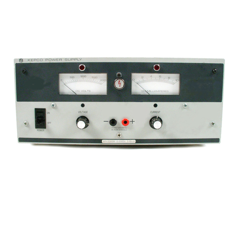
KEPCO BHK-MG Series User manual

IMPORTANT NOTES:
1) This manual is valid for the following Model and associated serial numbers:
MODEL SERIAL NO. REV. NO.
2) A Change Page may be included at the end of the manual. All applicable changes and
revision number changes are documented with reference to the equipment serial num-
bers. Before using this Instruction Manual, check your equipment serial number to identify
your model. If in doubt, contact your nearest Kepco Representative, or the Kepco Docu-
mentation Office in New York, (718) 461-7000, requesting the correct revision for your par-
ticular model and serial number.
3) The contents of this manual are protected by copyright. Reproduction of any part can be
made only with the specific written permission of Kepco, Inc.
Data subject to change without notice.
KEPCO®
THE POWER SUPPLIER™
MODEL
OPERATOR’S MANUAL
ORDER NO. REV. NO.
KEPCO, INC. 131-38 SANFORD AVENUE FLUSHING, NY. 11355 U.S.A. TEL (718) 461-7000 FAX (718) 767-1102
email: hq@kepcopower.com World Wide Web: http://www.kepcopower.com
KEPCO INC.
An ISO 9001 Company.
SERIES BHK-MG
40 WATT POWER SUPPLY
1/2 RACK VOLTAGE/CURRENT-STABILIZED DC SOURCE
BHK-MG 40 WATT
POWER SUPPLY
©2016, KEPCO, INC
P/N 243-0970-r6


A
228 1782 Dec of Conf BHK MG 40W (1/2 Rack) 200W (Full Rack)
Declaration of Conformity
Application of Council directives:
2006/95/EC (LVD)
2004/108/EC (EMC
Standard to which Conformity is declared:
IEC61010-1, 3rd Edition Safety requirements for electrical equipment for
measurement, control, and laboratory use
(designed to meet)
EN55011 (Class A, conducted and radiated)
(radiated is designed to meet)
Limits and Methods of Measurement of Radio
Disturbance Characteristics of Information
Technology Equipment (designed to meet)
EN61000-4-11, EN61000-4-4, EN61000-4-2,
EN61000-4-5, IEC61000-4-3, IEC61000-4-6,
IEC61000-4-8
Voltage Dips, Fast Transient_EFT,
ESD, Surge Immunity, Radiated Immunity
(designed to meet), Conducted Immunity,
Magnetic Field Immunity (designed to meet)
Manufacturer's Name:
Manufacturer's Address:
KEPCO, INC.
131-38 SANFORD AVENUE
FLUSHING NY 11355
USA
Importer's Name:
Importer's Address:
Type of Equipment:
Component Power Supply
Model Series
BHK-MG 40W (1/2 Rack), 200W
(Full Rack), all models, all
options
Model No.:
Year of Manufacture:
I, the undersigned, declare that the product specified above, when used in
conjunction with the conditions of conformance set forth in the product
instruction manual, complies with the requirements of the Low Voltage Directive
2006/95/EC, which forms the basis for application of the CE Mark to this
product.
Place: Kepco, Inc.
131-38 Sanford Ave.
Flushing NY 11355
USA
Date:
Mark Kupferberg
(Full Name)
Executive Vice President
(position)
REPRESENTATIVECOPY

B228-XXXX COND/CONFORM 030916
Conditions of Conformance
When this product is used in applications governed by the requirements of the EEC, the following restric-
tions and conditions apply:
1. For European applications, requiring compliance to the Low Voltage Directive, 73/23/EEC, this power
supply is considered a component product, designed for “built in“ applications. Because it is incom-
plete in construction, the end product enclosure must provide for compliance to any remaining electri-
cal safety requirements and act as a fire enclosure. (EN61010-1 Cl. 6, Cl. 7, Cl.8, Cl. 9 and EN61010-
1 annex F)
2. This power supply is designed for stationary installation, with mains power applied via a detachable
power supply cord or via direct wiring to the source power terminal block.
3. This power supply is considered a Class 1 (earthed) product, and as such depends upon proper con-
nection to protective earth for safety from electric shock. (EN61010-1 Cl. 6.5.4)
4. This power supply is intended for use as part of equipment meant for test, measurement and labora-
tory use, and is designed to operate from single phase, three wire power systems. This equipment
must be installed within a suitably wired equipment rack, utilizing a three wire (grounded) mains con-
nection. See wiring section of this manual for complete electrical wiring instructions. (EN61010-1 Cl.
6.5.4 and Cl.6.10.1)
5. This power supply has secondary output circuits that are considered hazardous, and which reach 40
VA at a potential of 300V or more.
6. The output wiring terminals of this power supply have not been evaluated for field wiring and, there-
fore, must be properly configured by the end product manufacturer prior to use.
7. This power supply employs a supplementary circuit protector in the form of a circuit breaker mounted
on the front panel. This circuit breaker protects the power supply itself from damage in the event of a
fault condition. For complete circuit protection of the end product, as well as the building wiring, it is
required that a primary circuit protection device be fitted to the branch circuit wiring. (EN61010-1 Cl.
9.6.2)
8. Hazardous voltages are present within this power supply during normal operation. All operator adjust-
ments to the product are made via externally accessible switches, controls and signal lines as speci-
fied within the product operating instructions. There are no user or operator serviceable parts within
the product enclosure. Refer all servicing to qualified and trained Kepco service technicians.

228-1353 SAFETY - (SWITCH) 030916 C/(D BLANK)
SAFETY INSTRUCTIONS
1. Installation, Operation and Service Precautions
This product is designed for use in accordance with EN 61010-1 and UL 3101 for Installation Category 2,
Pollution Degree 2. Hazardous voltages are present within this product during normal operation. The prod-
uct should never be operated with the cover removed unless equivalent protection of the operator from
accidental contact with hazardous internal voltages is provided:
2. Grounding
This product is a Class 1 device which utilizes protective earthing to ensure operator safety.
3. Electric Shock Hazards
This product outputs hazardous voltage and energy levels as a function of normal operation. Operators
must be trained in its use and exercise caution as well as common sense during use to prevent accidental
shock.
There are no operator serviceable parts or adjustments within the product enclosure.
Refer all servicing to trained service technician.
Source power must be removed from the product prior to performing any servicing.
This product is factory set for the nominal a-c mains voltage indicated by the Voltage
Range Selector switch located adjacent to the source power connection on the prod-
uct's rear panel. To reconfigure the product input for other nominal mains voltages as
listed herein, follow the applicable instructions shown in this manual.
NOTE: Source power must be removed from the product prior to changing the set-
ting of the Voltage Range Selector switch.
The PROTECTIVE EARTHING CONDUCTOR TERMINAL must properly con-
nected prior to application of source power to the product (see instructions on instal-
lation herein) in order to ensure safety from electric shock.
PROTECTIVE EARTHING CONDUCTOR TERMINAL - This symbol indicates the
point on the product to which the protective earthing conductor must be attached.
EARTH (GROUND) TERMINAL - This symbol is used to indicate a point which is
connected to the PROTECTIVE EARTHING TERMINAL. The component installer/
assembler must ensure that this point is connected to the PROTECTIVE EARTH-
ING TERMINAL.
CHASSIS TERMINAL -This symbol indicates frame (chassis) connection, which is
supplied as a point of convenience for performance purposes (see instructions on
grounding herein). This is not to be confused with the protective earthing point, and
may not be used in place of it.
This symbol appears adjacent to any external terminals at which hazardous voltage
levels as high as 500V d-c may exist in the course of normal or single fault condi-
tions.
This symbol appears adjacent to any external terminals at which hazardous voltage
levels in excess of 500V d-c may exist in the course of normal or single fault condi-
tions
!
!
!
!
!


BHK 1/2 RACK 020498 i
TABLE OF CONTENTS
SECTION PAGE
SECTION 1 - INTRODUCTION
1.1 Scope of Manual ..................................................................................................................................... 1-1
1.2 General Description................................................................................................................................. 1-1
1.3 Specifications.......................................................................................................................................... 1-2
1.4 Features.................................................................................................................................................. 1-9
1.4.1 Local Control...................................................................................................................................... 1-9
1.4.2 Remote Control.................................................................................................................................. 1-9
1.4.2.1 Digital Programming .................................................................................................................... 1-9
1.4.2.2 Analog Programming................................................................................................................... 1-9
1.4.2.3 Analog Readback......................................................................................................................... 1-9
1.4.3 Digital Calibration............................................................................................................................... 1-9
1.4.4 Overvoltage/Overcurrent Protection.................................................................................................. 1-10
1.4.5 User-defined Voltage/Current Limits.................................................................................................. 1-10
1.4.6 Nonvolatile Storage of Programmed Sequences or Active Settings.................................................. 1-10
1.4.7 Current Measurement Scale.............................................................................................................. 1-11
1.4.8 Fast Mode/Slow Mode Selection....................................................................................................... 1-11
1.4.9 Built-in Protection............................................................................................................................... 1-11
1.4.10 Analog Readback and Flag Signals Available for Customer Use...................................................... 1-12
1.4.11 External Trigger Port.......................................................................................................................... 1-12
1.4.12 Current Sink Capability...................................................................................................................... 1-13
1.5 Equipment Supplied................................................................................................................................ 1-13
1.6 Accessories............................................................................................................................................. 1-14
1.7 Safety...................................................................................................................................................... 1-14
SECTION 2 - INSTALLATION
2.1 Unpacking and Inspection....................................................................................................................... 2-1
2.2 Terminations and Controls ...................................................................................................................... 2-1
2.3 Source Power Requirements .................................................................................................................. 2-6
2.4 Cooling.................................................................................................................................................... 2-6
2.5 Preliminary Operational Check................................................................................................................ 2-7
2.6 Installation............................................................................................................................................... 2-8
2.6.1 Bench Top Use.................................................................................................................................. 2-8
2.6.2 Rack Mounting................................................................................................................................... 2-9
2.7 Wiring Instructions................................................................................................................................... 2-9
2.7.1 Safety Grounding............................................................................................................................... 2-9
2.7.2 Source Power Connections............................................................................................................... 2-9
2.7.3 D-C Output Grounding....................................................................................................................... 2-9
2.7.4 Power Supply/Load Interface............................................................................................................. 2-10
2.7.4.1 Cable Recommendations............................................................................................................. 2-11
2.7.5 Load Connection - General................................................................................................................ 2-11
2.7.5.1 Local Sensing/Remote Sensing Select........................................................................................ 2-12
2.7.5.2 Fast Mode/Slow Mode Select...................................................................................................... 2-12
2.7.5.3 Grounding Network Configuration................................................................................................ 2-12
2.7.5.4 Positive Output, Negative Terminal Grounded ............................................................................ 2-13
2.7.5.5 Negative Output, Positive Terminal Grounded ............................................................................ 2-13
2.8 Operating Configuration.......................................................................................................................... 2-13
2.9 Status Port............................................................................................................................................... 2-14
SECTION 3 - OPERATION
3.1 General.................................................................................................................................................... 3-1
3.2 Local Mode Operation............................................................................................................................. 3-1
3.2.1 Front Panel Keypad and LCD............................................................................................................ 3-1
3.2.1.1 Command Entry Status................................................................................................................ 3-1
3.2.1.2 Data Entry Status......................................................................................................................... 3-1
3.2.1.3 Display (LCD)............................................................................................................................... 3-1
3.2.1.4 Keypad Functions........................................................................................................................ 3-2

ii BHK 1/2 RACK 030916
TABLE OF CONTENTS
SECTION PAGE
3.2.2 Turning the Power Supply On........................................................................................................... 3-4
3.2.3 Error Conditions................................................................................................................................ 3-5
3.2.4 Setting Local Mode........................................................................................................................... 3-5
3.2.5 Adjusting LCD Contrast .................................................................................................................... 3-6
3.2.6 Enabling/Disabling Audible Beeps.................................................................................................... 3-6
3.2.7 Enabling/Disabling DC Output Power............................................................................................... 3-6
3.2.7.1 Disabling DC Output ................................................................................................................... 3-6
3.2.7.2 Disabling DC Output Using Remote On/Off Port ........................................................................ 3-6
3.2.7.3 Remote Shutdown using External Trigger Port........................................................................... 3-7
3.2.7.4 Power Up DC Output Control...................................................................................................... 3-7
3.2.8 Reset Operation................................................................................................................................ 3-7
3.2.8.1 Setting Power-Up & Reset Current............................................................................................. 3-7
3.2.9 Setting Output Voltage or Current..................................................................................................... 3-8
3.2.10 Setting Overvoltage or Overcurrent Protection................................................................................. 3-8
3.2.11 Changing Maximum Voltage or Current Value ................................................................................. 3-9
3.2.12 Storing Power Supply Output Settings.............................................................................................. 3-9
3.2.13 Recalling Stored Output Settings...................................................................................................... 3-10
3.2.14 Firmware Version.............................................................................................................................. 3-10
3.2.15 Local Mode Programming of the Power Supply................................................................................ 3-10
3.2.15.1 Creating or Modifying a Program (Program Edit Mode).............................................................. 3-10
3.2.15.1.1 Modifying Programmed Time Interval.....................................................................................3-12
3.2.15.1.2 Time Interval Accuracy...........................................................................................................3-12
3.2.15.2 Running a Program..................................................................................................................... 3-12
3.2.15.3 Stepping Through a Program...................................................................................................... 3-12
3.2.15.4 Cycling a Program....................................................................................................................... 3-13
3.2.15.5 Running a Program Once ........................................................................................................... 3-13
3.2.15.6 Stopping a Running Program...................................................................................................... 3-13
3.2.15.7 Sample Program......................................................................................................................... 3-13
3.2.16 Calibration......................................................................................................................................... 3-13
3.3 Remote Mode Programming Using SCPI commands via IEEE 488 (GPIB). Bus .................................. 3-14
3.3.1 IEEE 488 (GPIB) Bus Protocol ......................................................................................................... 3-14
3.3.2 DCL Control...................................................................................................................................... 3-15
3.3.3 Changing the GPIB Address............................................................................................................. 3-16
3.3.4 External Trigger ................................................................................................................................ 3-16
3.3.5 Programming Techniques to Optimize performance ........................................................................ 3-16
3.3.5.1 Programming Voltage/Current Limit and Current/Voltage Limit.................................................. 3-16
3.3.5.2 Making Sure the Previous Command is Complete ..................................................................... 3-17
3.4 BHK-MG VISA Instrument driver............................................................................................................ 3-18
3.5 RS232-C Operation................................................................................................................................ 3-19
3.5.1 Setting RS 232 Baud Rate................................................................................................................ 3-19
3.5.2 Serial INterface................................................................................................................................. 3-19
3.5.3 RS 232 Implementation .................................................................................................................... 3-19
3.5.3.1 Echo Mode.................................................................................................................................. 3-20
3.5.3.2 Prompt Method............................................................................................................................ 3-21
3.5.3.3 XON XOFF Method..................................................................................................................... 3-21
3.5.4 Isolating RS 232 Communication Problems ..................................................................................... 3-21
3.6 Programming Techniques to Optimize performance.............................................................................. 3-22
3.6.1 Example of Proper Programming...................................................................................................... 3-22
3.6.2 Explanation of Programming Techniques......................................................................................... 3-22
3.7 SCPI Programming................................................................................................................................. 3-22
3.7.1 SCPI Messages................................................................................................................................ 3-23
3.7.2 Common Commands/Queries .......................................................................................................... 3-23
3.7.3 SCPI Subsystem Command/Query Structure................................................................................... 3-23
3.7.3.1 ABORt Subsystem...................................................................................................................... 3-23
3.7.3.2 INITiate Subsystem..................................................................................................................... 3-23
3.7.3.3 LIST Subsystem.......................................................................................................................... 3-23
3.7.3.4 MEASure Subsystem.................................................................................................................. 3-23
3.7.3.5 OUTPut Subsystem .................................................................................................................... 3-23

BHK 1/2 RACK 020498 iii
TABLE OF CONTENTS
SECTION PAGE
3.7.3.6 Instrument Subsystem................................................................................................................. 3-24
3.7.3.7 STATus Subsystem..................................................................................................................... 3-24
3.7.3.8 System Subsystem...................................................................................................................... 3-24
3.7.3.9 TRIGger subsystem..................................................................................................................... 3-24
3.7.3.10 [SOURce:]VOLTage and [SOURce:]CURRent Subsystems....................................................... 3-24
3.7.3.11 CALibrate Subsystem.................................................................................................................. 3-24
3.7.4 Program Message Structure.............................................................................................................. 3-26
3.7.4.1 Keyword....................................................................................................................................... 3-26
3.7.4.2 Keyword Separator...................................................................................................................... 3-27
3.7.4.3 Query Indicator ............................................................................................................................ 3-27
3.7.4.4 Data ............................................................................................................................................. 3-27
3.7.4.5 Data Separator............................................................................................................................. 3-27
3.7.4.6 Message Unit Separator.............................................................................................................. 3-27
3.7.4.7 Root Specifier .............................................................................................................................. 3-27
3.7.4.8 Message Terminator.................................................................................................................... 3-28
3.7.5 Understanding The Command Structure........................................................................................... 3-28
3.7.6 Program Message Syntax Summary................................................................................................. 3-29
3.7.7 SCPI Program Examples................................................................................................................... 3-29
3.8 Remote Programming Using Analog Programming Terminals................................................................ 3-30
3.8.1 Analog Programming Warnings and Cautions................................................................................... 3-33
3.8.2 Programming with external resistance............................................................................................... 3-34
3.8.2.1 Voltage Mode............................................................................................................................... 3-36
3.8.2.2 Current Mode............................................................................................................................... 3-37
3.8.3 Programming with external voltage using a low impedance Voltage source..................................... 3-37
3.8.3.1 Voltage Mode............................................................................................................................... 3-41
3.8.3.2 Current Mode............................................................................................................................... 3-42
3.8.4 Programming with external voltage using a high impedance, low level (1V) Voltage source............ 3-42
3.8.4.1 Voltage Mode............................................................................................................................... 3-45
3.8.4.2 Current Mode............................................................................................................................... 3-45
3.8.5 Programming with external current source (1 mA)............................................................................ 3-46
3.8.5.1 Voltage Mode............................................................................................................................... 3-48
3.8.5.2 Current Mode............................................................................................................................... 3-48
3.9 Operating Modes..................................................................................................................................... 3-49
3.9.1 Slow/Fast mode of operation............................................................................................................. 3-49
3.9.2 Series operation................................................................................................................................. 3-51
3.9.2.1 Automatic series operation .......................................................................................................... 3-52
3.9.2.2 Master-slave series operation (Automatic Tracking).................................................................... 3-55
3.9.2.2.1 Voltage Mode Operation.........................................................................................................3-55
3.9.2.2.2 Current Mode Operation .........................................................................................................3-58
3.9.3 Parallel operation............................................................................................................................... 3-60
3.9.3.1 Automatic parallel operation ........................................................................................................ 3-61
3.9.3.2 Master-slave parallel operation.................................................................................................... 3-63
3.9.3.2.1 Voltage Mode Operation.........................................................................................................3-64
3.9.3.2.2 Current Mode Operation .........................................................................................................3-66
SECTION 4 - CALIBRATION
4.1 General.................................................................................................................................................... 4-1
4.2 Equipment Required................................................................................................................................ 4-1
4.3 Calibration Description............................................................................................................................ 4-1
4.4 Calibration Using Front Panel Keys ........................................................................................................ 4-2
4.4.1 Voltage Calibration ............................................................................................................................ 4-2
4.4.2 Current Calibration............................................................................................................................. 4-3
4.5 Calibration Using IVI Driver..................................................................................................................... 4-4
4.5.1 Setup ................................................................................................................................................. 4-4
4.5.2 Main Control Panel............................................................................................................................ 4-5
4.5.3 Calibration Controls........................................................................................................................... 4-6

iv BHK 1/2 RACK 030916
TABLE OF CONTENTS
SECTION PAGE
4.5.4 Calibration Procedure....................................................................................................................... 4-7
4.6 Changing the Calibration Password ....................................................................................................... 4-9
4.7 Restoring Previous Calibration Values................................................................................................... 4-9
4.8 Restoring Factory Calibration Values..................................................................................................... 4-9
4.9 Calibration Storage................................................................................................................................. 4-10
APPENDIX A - IEEE 488.2 COMMAND/QUERY DEFINITIONS
A.1 Introduction............................................................................................................................................. A-1
A.2 *CLS — Clear Status Command ............................................................................................................ A-1
A.3 *ESE — Standard Event Status Enable Command................................................................................ A-1
A.4 *ESE? — Standard Event Status Enable Query..................................................................................... A-1
A.5 *ESR? — Event Status Register Query.................................................................................................. A-2
A.6 *IDN? — Identification Query.................................................................................................................. A-2
A.7 *OPC — Operation Complete Command............................................................................................... A-2
A.8 *OPC? — Operation Complete Query.................................................................................................... A-2
A.9 *RCL — Recall Command...................................................................................................................... A-2
A.10 *RST — Reset Command....................................................................................................................... A-3
A.11 * SAV — Save Command....................................................................................................................... A-3
A.12 *SRE — Service Request Enable Command......................................................................................... A-4
A.13 *SRE? — Service Request Enable Query.............................................................................................. A-4
A.14 *STB? — Status Byte Register Query.................................................................................................... A-4
A.15 *TRG — Trigger Command.................................................................................................................... A-4
A.16 *TST? — Self Test Query....................................................................................................................... A-4
APPENDIX B - SCPI COMMAND/QUERY DEFINITIONS
B.1 Introduction............................................................................................................................................. B-1
B.2 Numerical Values.................................................................................................................................... B-2
B.3 ABORt Command................................................................................................................................... B-2
B.4 CAL Commands and Queries................................................................................................................. B-2
B.5 DISPlay:CONTrast Command................................................................................................................ B-2
B.6 DISPlay:CONTrast? Query..................................................................................................................... B-2
B.7 DISPlay:MODE Command ..................................................................................................................... B-4
B.8 DISPlay:MODE? Query.......................................................................................................................... B-4
B.9 DISPlay:TEXT Command....................................................................................................................... B-4
B.10 DISPlay:TEXT? Query............................................................................................................................ B-4
B.11 INITiate[:IMMediate] Command.............................................................................................................. B-4
B.12 INITiate:CONTinuous Command............................................................................................................ B-4
B.13 INITiate:CONTinuous? Query................................................................................................................. B-5
B.14 INSTrument:STATe Command............................................................................................................... B-5
B.15 INSTrument:STATe? Query.................................................................................................................... B-5
B.16 [SOURce:]LIST:CLEar Command.......................................................................................................... B-5
B.17 [SOURce:]LIST:COUNt Command......................................................................................................... B-5
B.18 [SOURce:]LIST:COUNt? Query.............................................................................................................. B-5
B.19 [SOURce:]LIST:COUNt:SKIP Command................................................................................................ B-5
B.20 [SOURce:]LIST:COUNt:SKIP? Query .................................................................................................... B-6
B.21 [SOURce:]LIST:CURRent Command..................................................................................................... B-6
B.22 [SOURce:]LIST:CURRent? Query.......................................................................................................... B-6
B.23 [SOURce:]LIST:CURRent:POINts? Query............................................................................................. B-6
B.24 [SOURce:]LIST:DIRection Command..................................................................................................... B-6
B.25 [SOURce:]LIST:DIRection? Query ......................................................................................................... B-6
B.26 [SOURce:]LIST:DWELl Command......................................................................................................... B-6
B.27 [SOURce:]LIST:DWELl? Query.............................................................................................................. B-7
B.28 [SOURce:]LIST:DWELl:POINts? Query ................................................................................................. B-7
B.29 [SOURce:]LIST:QUERy Command........................................................................................................ B-7
B.30 [SOURce:]LIST:QUERy? Query............................................................................................................. B-7

BHK 1/2 RACK 020498 v
TABLE OF CONTENTS
SECTION PAGE
B.31 [SOURce:]LIST:VOLTage Command..................................................................................................... B-7
B.32 [SOURce:]LIST:VOLTage? Query.......................................................................................................... B-7
B.33 [SOURce:]LIST:VOLTage:POINts? Query ............................................................................................. B-7
B.34 MEASure[:SCALar]:CURRent[:DC]? Query........................................................................................... B-9
B.35 MEASure:VOLTage[:SCALar][:DC]? Query ........................................................................................... B-9
B.36 OUTPut[:STATe] Command................................................................................................................... B-9
B.37 OUTPut[:STATe]? Query........................................................................................................................ B-10
B.38 [SOURce:]CURRent[:LEVel][:IMMediate][:AMPlitude] Command.......................................................... B-10
B.39 [SOURce:]CURRent[:LEVel][:IMMediate][:AMPlitude]? Query............................................................... B-10
B.40 [SOURce:]CURRent:LIMit[:HIGH] Command......................................................................................... B-10
B.41 [SOURce:]CURRent:LIMit[:HIGH]? Query ............................................................................................. B-10
B.42 [SOURce:]CURRent:MODE Command.................................................................................................. B-11
B.43 [SOURce:]CURRent:MODE? Query ...................................................................................................... B-11
B.44 [SOURce:]CURRent:PROTection[:LEVel] Command............................................................................. B-11
B.45 [SOURce:]CURRent:PROTection[:LEVel]? Query.................................................................................. B-11
B.46 [SOURce:]CURRent:[:LEVel]TRIGgered[:AMPlitude] Command........................................................... B-11
B.47 [SOURce:]CURRent:[:LEVel]TRIGgered[:AMPlitude] ? Query............................................................... B-11
B.48 [SOURce:]VOLTage[:LEVel][:IMMediate][:AMPlitude] Command.......................................................... B-12
B.49 [SOURce:]VOLTage[:LEVel][:IMMediate][:AMPlitude]? Query............................................................... B-12
B.50 [SOURce:]VOLTage:LIMit[:HIGH] Command......................................................................................... B-12
B.51 [SOURce:]VOLTage:LIMit[:HIGH]? Query.............................................................................................. B-12
B.52 [SOURce:]VOLTage:MODE Command.................................................................................................. B-13
B.53 [SOURce:]VOLTage:MODE? Query....................................................................................................... B-13
B.54 [SOURce:]VOLTage:PROTection[:LEVel] Command............................................................................. B-13
B.55 [SOURce:]VOLTage:PROTection[:LEVel]? Query.................................................................................. B-13
B.56 [SOURce:]VOLTage:[:LEVel]TRIGgered[:AMPlitude] Command........................................................... B-13
B.57 [SOURce:]VOLTage:[:LEVel]TRIGgered[:AMPlitude]? Query................................................................ B-13
B.58 [SOURce:]FUNCtion:MODE? Query...................................................................................................... B-14
B.59 STATus:OPERation:CONDition? Query................................................................................................. B-14
B.60 STATus:OPERation:ENABle Command ................................................................................................ B-14
B.61 STATus:OPERation:ENABle? Query..................................................................................................... B-15
B.62 STATus:OPERation[:EVENt] Query....................................................................................................... B-15
B.63 STATus:PRESet Command................................................................................................................... B-15
B.64 STATus:QUEStionable[:EVENt]? Query ................................................................................................ B-16
B.65 STATus:QUEStionable:CONDition? Query............................................................................................ B-16
B.66 STATus:QUEStionable:ENABle Command............................................................................................ B-16
B.67 STATus:QUEStionable:ENABle? Query................................................................................................. B-16
B.68 SYSTem:BEEP Command..................................................................................................................... B-16
B.69 SYSTem:COMMunication:GPIB:ADDRess Command ......................................................................... B-17
B.70 SYSTem:COMMunication:GPIB:ADDRess? Query................................................................................ B-17
B.71 SYSTem:COMMunication:SERial:BAUD Command.............................................................................. B-17
B.72 SYSTem:COMMunication:SERial:BAUD? Query................................................................................... B-17
B.73 SYSTem:COMMunication:SERial:ECHO Command ............................................................................ B-17
B.74 SYSTem:COMMunication:SERial:ECHO? Query................................................................................... B-17
B.75 SYSTem:COMMunication:SERial:PACE Command .............................................................................. B-17
B.76 SYSTem:COMMunication:SERial:PACE? Query................................................................................... B-17
B.77 SYSTem:COMMunication:SERial:PROMpt Command......................................................................... B-18
B.78 SYSTem:COMMunication:SERial:PROMpt? QUERY........................................................................... B-18
B.79 SYSTem:ERRor? Query......................................................................................................................... B-18
B.80 SYSTem:ERRor:CODE? Query ............................................................................................................. B-18

vi BHK 1/2 RACK 030916
TABLE OF CONTENTS
SECTION PAGE
B.81 SYSTem:ERRor:CODE:ALL? Query ...................................................................................................... B-18
B.82 SYSTem:KLOCk Command.................................................................................................................... B-18
B.83 SYSTem:KLOCk? Query ........................................................................................................................ B-19
B.84 SYSTem:PASSword:CENable Command .............................................................................................. B-19
B.85 SYSTem:PASSword:CDISable Command ............................................................................................. B-19
B.86 SYSTem:PASSword:NEW Command .................................................................................................... B-19
B.87 SYSTem:PASSword:STATe? Query....................................................................................................... B-19
B.88 SYSTem:SECurity:IMMediate Command............................................................................................... B-19
B.89 SYSTem:VERSion? Query ..................................................................................................................... B-20
B.90 TRIGger:SOURce Command................................................................................................................. B-20

LIST OF FIGURES
FIGURE TITLE PAGE
BHK 1/2 RACK 030916 vii
1-1 BHK-MG 40W Series Programmable Power Supply.................................................................................... xii
1-2 BHK 40W Series Power Supply, Mechanical Outline Drawing .................................................................. 1-6
1-3 RA 24 Rack Adapter with two 1/2 Rack BHK-MG 40W Units .................................................................... 1-8
1-4 Connector A2J5 Location........................................................................................................................... 1-10
2-1 BHK-MG Series, Front Panel Controls, Indicators and Connectors........................................................... 2-1
2-2 BHK-MG Series, Rear Panel Controls and Connections ........................................................................... 2-3
2-3 LCD Power On Defaults............................................................................................................................. 2-7
2-4 Local Sensing, Slow Mode Selected, Grounding Network Connected,
Floating Output (Factory Default Configuration)...................................................................................... 2-12
2-5 Remote Sensing, Fast Mode Selected, Positive Output Grounded ........................................................... 2-13
2-6 Status Port Opto-coupler Active “LOW” Configuration............................................................................... 2-14
2-7 Status Port Opto-coupler Active “HIGH” Configuration.............................................................................. 2-14
3-1 LCD Power On States................................................................................................................................ 3-5
3-2 Programming Example to Verify Previous Command has Completed....................................................... 3-18
3-3 RS 232 Implementation.............................................................................................................................. 3-20
3-4 Tree Diagram of SCPI Commands Used with BHK-MG 40W Power Supply............................................. 3-25
3-5 Message Structure..................................................................................................................................... 3-26
3-6 Typical Example Of BHK-MG 40W Power Supply Program Using SCPI Commands ............................... 3-30
3-7 Analog Voltage Programming, Simplified Diagram .................................................................................... 3-31
3-8 Analog Current Programming, Simplified Diagram .................................................................................... 3-31
3-9 Analog Programming of Output Voltage (Voltage Mode)
or Voltage Limit (Current Mode) using Resistance.................................................................................. 3-35
3-10 Analog Programming of Output Current (Current Mode)
or Current Limit (Voltage Mode) using Resistance................................................................................. 3-36
3-11 Analog Programming of Output Voltage (Voltage Mode) or Voltage Limit
(Current Mode) using Isolated (floating) Low Impedance Voltage Source (VS)..................................... 3-38
3-12 Analog Programming of Output Voltage (Voltage Mode) or Voltage
Limit (Current Mode) using Grounded Low Impedance Voltage Source (VS)........................................ 3-39
3-13 Analog Programming of Output Current (Current Mode) or Current Limit
(Voltage Mode) using Isolated (Floating) Low Impedance Voltage Source (VS) ................................... 3-40
3-14 Analog Programming of Output Current (Current Mode) or Current
Limit (Voltage Mode) using Grounded Low Impedance Voltage Source (VS)........................................ 3-41
3-15 Analog Programming of Output Voltage (Voltage Mode) or Voltage
Limit (Current Mode) using High Impedance, Low Level (1V) Voltage Source (VS).............................. 3-43
3-16 Analog Programming of Output Current (Current Mode) or Current
Limit (Voltage Mode) using High Impedance, Low Level (1V) Voltage Source (VS).............................. 3-44
3-17 Analog Programming of Output Voltage (Voltage Mode) or Voltage
Limit (Current Mode) using Current Source (1mA) (CS) ........................................................................ 3-46
3-18 Analog Programming of Output Current (Current Mode) or Current
Limit (Voltage Mode) using Current Source (1mA) (CS) ........................................................................ 3-47
3-19 Slow Mode/Fast Mode Operation............................................................................................................... 3-50
3-20 Series Automatic Configuration.................................................................................................................. 3-54
3-21 Series Master-Slave (Voltage Mode) Configuration................................................................................... 3-57
3-22 Series Master-Slave (Current Mode) Configuration ................................................................................... 3-58
3-23 Parallel Automatic Configuration................................................................................................................ 3-62
3-24 Parallel Master-Slave (Voltage Mode) Configuration................................................................................. 3-64
3-25 Parallel Master-Slave (Current Mode) Configuration ................................................................................. 3-67
4-1 Input VISA Resource Descriptor ................................................................................................................ 4-5
4-2 Main Control Panel, Typical ....................................................................................................................... 4-5
4-3 Calibration Controls.................................................................................................................................... 4-6
4-4 Password Entry.......................................................................................................................................... 4-7
4-5 Voltage Calibration..................................................................................................................................... 4-7
4-6 Current Magnifier Window.......................................................................................................................... 4-8
A-1 GPIB Commands ....................................................................................................................................... A-3
B-1 Programming the Output............................................................................................................................ B-3
B-2 Using Display Commands.......................................................................................................................... B-3
B-3 Using LIST Commands and Queries.......................................................................................................... B-8
B-4 Programming Current................................................................................................................................. B-12

LIST OF FIGURES
FIGURE TITLE PAGE
viii BHK 1/2 RACK 030916
B-5 Programming Voltage................................................................................................................................. B-14
B-6 Using Status Commands and Queries....................................................................................................... B-15
B-7 Using System Commands and Queries..................................................................................................... B-19

BHK 1/2 RACK 03916 ix/(viii Blank)
LIST OF TABLES
TABLE TITLE PAGE
1-1 Model Parameters .......................................................................................................................................1-2
1-2 BHK-MG 40W Specifications ......................................................................................................................1-2
1-3 Connector A2J5 Signal Descriptions ..........................................................................................................1-12
1-4 Equipment Supplied ....................................................................................................................................1-13
1-5 Accessories .................................................................................................................................................1-14
1-6 Safety Symbols ...........................................................................................................................................1-14
2-1 Controls, Indicators, and Connectors ..........................................................................................................2-2
2-2 IEEE 488 Port Connector Pin Assignments ................................................................................................2-4
2-3 Status and Remote On/Off Port Connector Pin Assignments .....................................................................2-4
2-4 RS 232C PORT Input/Output Pin Assignments ..........................................................................................2-5
2-5 External Trigger Port Pin Assignments .......................................................................................................2-5
2-6 Rear Output Terminal Strip A6TB1, Terminal Assignments ........................................................................2-5
2-7 Voltage Programming Terminal Strip A6TB2, Terminal Assignments ........................................................2-5
2-8 Current Programming Terminal Strip A6TB3, Terminal Assignments .........................................................2-6
2-9 Internal Jumper Configuration .....................................................................................................................2-14
3-1 LCD Messages ...........................................................................................................................................3-2
3-2 Key Functions .............................................................................................................................................3-2
3-3 Error Conditions ..........................................................................................................................................3-5
3-4 Memory Location Worksheet ......................................................................................................................3-11
3-5 Sample Program (Model BHK-MG 500-80MG) ...........................................................................................3-13
3-6 IEEE 488 (GPIB) Bus Interface Functions ..................................................................................................3-14
3-7 IEEE 488 (GPIB) Bus Command Mode Messages .....................................................................................3-15
3-8 IEEE 488 (GPIB) Bus Data Mode Messages ..............................................................................................3-15
3-9 Rules Governing Shortform Keywords ........................................................................................................3-27
3-10 Feedback Resistor and Current Sensing Resistor Values ..........................................................................3-35
4-1 VISA Resource String Corresponding to Interface .....................................................................................4-4
4-2 Calibration Panel Functions ........................................................................................................................4-6
4-3 Factory Default Calibration Passwords .......................................................................................................4-9
4-4 Calibration Storage .....................................................................................................................................4-10
A-1 IEEE 488.2 Command/query Index ...........................................................................................................A-1
A-2 Standard Event Status Enable Register and Standard Event Status Register Bits ...................................A-1
A-3 Service Request Enable and Status Byte Register Bits .............................................................................A-4
B-1 SCPI Subsystem Command/query Index ..................................................................................................B-1
B-2 Operation Condition Register, Operation Enable Register,
and Operation Event Register Bits ..........................................................................................................B-14
B-3 Questionable Event Register, Questionable Condition Register,
and Questionable Condition Enable Register Bits ..................................................................................B-16
B-4 Error Messages ..........................................................................................................................................B-20


BHK-MG 030916 xi
SERVICE
SAFETY INSTRUCTIONS
Read these safety instructions, as well as the applicable installation, operating and servicing instructions
contained in this manual before using the power supply.
Do not touch the output terminals. The high voltage output is dangerous. Electric shock can cause injury or
death.
Do not remove the cover or disassemble the unit. There are no operator serviceable components or
adjustments inside the unit. High voltage components inside the unit can cause serious injury even with
input power disconnected.
CAUTION
If this power supply is used in OEM equipment, the OEM equipment manufacturer is responsible for
attaching appropriate warning labels on the OEM equipment.
Operating the power supply outside the specified limits for input voltage, temperature, or other environ-
mental conditions noted in this manual can damage the power supply and void the warranty.
Safety Messages
The BHK-MG can be controlled by digital and/or analog inputs. When the output is disabled, whether by
the OUTPUT ON/OFF key, SCPI command via GPIB or RS 232 interface, or via the Status and Remote
On/Off Port, an internal solid-state switch sets the voltage/current references to zero, resulting in zero out-
put from the power supply. In the case of the OUTPUT ON/OFF key or SCPI command, if the solid state
switch fails, and the output is higher than 8V, and the current is higher than two LSBs, a shutdown
sequence begins: the unit beeps and flashes the message Power Down in XX sec for 10 seconds as
XX counts down from 10 to 0. After 10 seconds the input circuit breaker trips OFF. If the circuit breaker
does not trip OFF, BHK Failure is displayed on the LCD.
There are no operator serviceable parts inside the case. Service must be referred to authorized personnel.
Using the power supply in a manner not specified by Kepco. Inc. may impair the protection provided by the
power supply. Observe all safety precautions noted throughout this manual. The following table lists sym-
bols used on the power supply or in this manual where applicable.
SAFETY SYMBOLS
SYMBOL Meaning SYMBOL Meaning
WARNING: RISK OF ELECTRIC
SHOCK. WARNING INDICATES THE POSSIBILITY
OF BODILY INJURY OR DEATH.
CAUTION: REFER TO REFER-
ENCED PROCEDURE. CAUTION INDICATES THE POSSIBILITY
OF EQUIPMENT DAMAGE.
WARNING
!

xii BHK-MG030916
FIGURE 1-1. BHK-MG 40W SERIES PROGRAMMABLE POWER SUPPLY

BHK-1/2-MG (OPR) 030916 1-1
SECTION 1 - INTRODUCTION
1.1 SCOPE OF MANUAL
This manual contains instructions for the installation, operation and service of the Half Rack
BHK-MG 40W series of output power stabilized voltage or current, d-c power supplies manufac-
tured by KEPCO, Inc., Flushing, New York, U.S.A.
DANGEROUS AND LETHAL POTENTIALS ARE PRESENT,
BOTH WITHIN THIS POWER SUPPLY, AND AT THE OUTPUT!
Before proceeding to use the power supply, read this manual very care-
fully. Caution must be used when working with, and making connections
to, this power supply. Use only wires with the proper voltage rating for
high voltage connections. Use the designated plugs for the front panel
output. Be extremely careful when analog programming inputs are used,
especially with the negative output of the power supply grounded.
Unless otherwise specified, always connect the test and measuring
equipment to the input power source using an isolating transformer hav-
ing a suitable isolating voltage rating. Follow all instructions regarding the
grounding of the test set-up. Refer all servicing to qualified service per-
sonnel only.
1.2 GENERAL DESCRIPTION
The BHK-MG 40W Power Supply Series (Figure 1-1) are full-range, automatic crossover, linear
voltage/current stabilizers with a full rectangular output characteristic. Four single-output models
are available as listed in Table1-1.
Although designed as a stand-alone bench top unit, the half-rack cross section permits mount-
ing two units side by side in a standard 19-inch wide rack using Kepco’s RA 24 Rack Adapter
(see Figure 1-3). Connections can be made at both rear output terminals (recommended for
rack mounted configurations) and front output terminals (recommended for bench applications).
Rear connections are made from a drawer-type access panel that is pulled out for installation of
connections, and then inserted and secured during operation. Sensing output terminals are
available at the rear terminals only. These power supplies operate from either 115V or 230V a-c
(nominal - switch selectable), 50 or 60 Hz (nominal) input source power. Since there are no
internal adjustments, BHK-MG 40W Power Supplies offer excellent output voltage/current stabil-
ity and easy calibration.
Output voltage and current are displayed on an alphanumeric Liquid Crystal Display (LCD).
Control of the BHK-MG 40W can be either local, via the front panel keypad and display, or
remote - using either analog signals (applied to Analog Programming Terminals), or digital pro-
gramming via the IEEE 488.2 (GPIB) communication bus. Both digital control (either local or
remote) and analog control can be used simultaneously. Digital control is done with 12 bits of
resolution over the entire voltage/current range.
WARNING

1-2 BHK-1/2-MG (OPR) 030916
1.3 SPECIFICATIONS
Table 1-1 lists the parameters applicable to individual models. Table 1-2 lists general specifica-
tions applicable to all models except where otherwise noted.
TABLE 1-1. MODEL PARAMETERS
MODEL
NUMBER
OUTPUT
VOLTAGE
RANGE
(VOLTS)
OUTPUT
CURRENT
RANGE
(mA)
MAXIMUM
OUTPUT
POWER
(WATTS)
OUTPUT EQUIVALENT IMPEDANCE (FAST MODE)
VOLTAGE MODE
(SERIES R–L) CURRENT MODE
(PARALLEL R–C)
Rd-c (Ohms) L (mH) Rd-c (MOhms) C (F)
BHK 300-130MG 0 - 300 0 - 130 39 0.115 See Note 15.4 See Note
BHK 500-80MG 0 - 500 0 - 80 40 0.313 See Note 41.7 See Note
BHK 1000-40MG 0 - 1000 0 - 40 40 4.25 See Note 166.7 See Note
BHK 2000-20MG 0 - 2000 0 - 20 40 5.0 See Note 666.7 See Note
NOTE: Contact Kepco for assistance.
TABLE 1-2. BHK-MG 40W SPECIFICATIONS
SPECIFICATION RATING/DESCRIPTION CONDITION
INPUT CHARACTERISTICS
a-c Voltage nominal (switch select-
able) 115/230V a-c Single phase
range (switch selectable) 105-125/210-250V a-c
Frequency nominal 50/60Hz
range 47-63Hz
Current 115V a-c 1.1A a-c Nominal power at output
230V a-c 0.6A a-c
OUTPUT CHARACTERISTICS
NOTE: Current specifications contained in this table refer to source current (delivered by the unit to the load). Sink current (absorbed
by the unit from the load) occurs when the output voltage is programmed to a lower value. The sink current is constant, toler-
ance 80% to 100% of rating; it flows until the output reaches the lower voltage.
Type of Stabilizer Linear with automatic cross-
over Voltage/Current
Adjustment range
(Adjustment is either continu-
ous using analog program-
ming, or stepped using digital
programming)
Voltage 0 to 100% of rating See PAR. 1.4.2.2 and 1.4.2.3 for details
about analog programming and read-
back.
Current 0-100% of rating
Digital Programming resolu-
tion Voltage and Current 0.025% of rating Current measurement requires calibrated
shunt
Digital Programming accuracy Voltage 0.025% of rating
Current 0.05% of rating Current measurement requires calibrated
shunt
Digital Data Readback
accuracy Voltage 0.05% of rating
Current 0.05% of rating 10-100% of rating
0.01% of rating <10% of rating (automatic 10X magnifier)
Source effect Voltage 0.001% EOmax Input voltage
105-125/210-250V a-c
Current 0.002% IOmax
Table of contents
Other KEPCO Power Supply manuals

KEPCO
KEPCO ATE 6-5 User manual

KEPCO
KEPCO TBC 12-50M User manual

KEPCO
KEPCO HSF 5-60M User manual

KEPCO
KEPCO EFX 150-T User manual

KEPCO
KEPCO PAT 40-0.5 User manual

KEPCO
KEPCO FPD 15-6.6-24 User manual

KEPCO
KEPCO HSP-A Series User manual

KEPCO
KEPCO BOP-2KW MG User manual

KEPCO
KEPCO KLP 10-150-(2) User manual

KEPCO
KEPCO BOP 400W User manual

KEPCO
KEPCO PAT 7-2 User manual

KEPCO
KEPCO BOP 1KW-MG Series User manual

KEPCO
KEPCO BOP 100W User manual

KEPCO
KEPCO TBC Series User manual

KEPCO
KEPCO MTW 60W User manual

KEPCO
KEPCO HSF A User manual

KEPCO
KEPCO BOP 1KW-G User manual

KEPCO
KEPCO EFX 100-T User manual

KEPCO
KEPCO RAX 3.3-10K User manual

KEPCO
KEPCO BOP 1000W User manual