Sony SIU-80 User manual

SYSTEM INTERFACE UNIT
SIU-80
BACKUP POWER SUPPLY
BKSI-PS80
1st Edition (Revised 1)
OPERATION MANUAL Japanese/English
電気製品は、安全のための注意事項を守らないと、火災
や人身事故になることがあり、危険です。
このオペレーションマニュアルには、事故を防ぐための重要な注意事項と製
品の取り扱いかたを示してあります。このオペレーションマニュアルをよく
お読みのうえ、製品を安全にお使いください。お読みになったあとは、いつ
でも見られるところに必ず保管してください。
警告
Serial No. 10001 and Higher (SIU-80)
Serial No. 10001 and Higher (BKSI-PS80)

2 (J)
電気製品はまちがった使い方をすると、火災や感電などにより死亡や大けが
など人身事故につながることがあり、危険です。
事故を防ぐために次のことを必ずお守りください。
安全のための注意事項を守る
2 (J) 〜3 (J) ページの注意事項をよくお読みください。
オプションユニットの装着について
危険を避けるため、オプションユニットの装着はサービストレーニングを受
けた技術者、もしくは本機を購入された販売会社またはソニー株式会社にご
依頼ください。
定期点検を実施する
長期間安全に使用していただくために、定期点検を実施することをおすすめ
します。点検の内容や費用については、本機を購入された販売会社またはソ
ニー株式会社にご相談ください。
故障したら使用を中止する
本機を購入された販売会社またはソニー株式会社にご連絡ください。
万一、異常が起きたら
安全のために
警告表示の意味
このオペレーションマニュアル
および製品では、次のような表
示をしています。表示の内容を
よく理解してから本文をお読み
ください。
警告
この表示の注意事項を守らない
と、火災や感電などにより死亡
や大けがなど人身事故につなが
ることがあります。
注意
この表示の注意事項を守らない
と、感電やその他の事故により
けがをしたり周辺の物品に損害
を与えたりすることがあります。
注意を促す記号
行為を禁止する記号
行為を指示する記号
火災 感電
注意
禁止
分解禁止
強制
アース線を
接続せよ
•異常な音、
におい、煙
が出たら
•内部に水、
異物が入っ
たら
•製品を落と
したり、
キャビネッ
トを破損さ
せたときは
/1電源を切る。
2電源コードや接続コードを抜く。
3本機を購入された販売会社またはソニー株式会
社に修理を依頼する。
すぐに電源を切り、消火する。
炎が出たら /

1 (J)
目次
警告 ......................................................................................................................2 (J)
注意 ......................................................................................................................3 (J)
概要 ...........................................................................................................................4 (J)
各部の名称と働き ....................................................................................................5 (J)
前面......................................................................................................................5 (J)
後面......................................................................................................................6 (J)
仕様 ...........................................................................................................................7 (J)
日
本
語

2 (J)
外装を外さない、改造しない
外装を外したり、改造したりすると、感電の原因となります。
内部の点検等の整備を行う必要がある場合は、必ずサービストレーニングを
受けた技術者にご依頼ください。
内部に水や異物を入れない
水や異物が入ると火災の原因となります。
万一、水や異物が入ったときは、すぐに電源を切り、電源コードや接続コー
ドを抜いて、本機を購入された販売会社またはソニー株式会社にご相談くだ
さい。
指定された電源コードを使用する
指定以外の電源コードを使用すると、火災や感電の原因となります。
電源コードを傷つけない
電源コードを傷つけると、火災や感電の原因となります。
・電源コードを加工したり、傷つけたりしない。
・重いものをのせたり、引っ張ったりしない。
・熱器具に近づけたり、加熱したりしない。
・電源コードを抜くときは、必ずプラグを持って抜く。
万一、電源コードが傷んだら、本機を購入された販売会社またはソニー株式
会社にご相談ください。
油煙、湯気、湿気、ほこりの多い場所では設置 •使用しない
上記のような場所で設置・使用すると、火災や感電の原因となります。
表示された電源電圧で使用する
製品に表示されたものと異なる電源電圧で使用すると、火災や感電の原因と
なります。
下記の注意を守らないと、
火災や感電により死亡や大けがにつながることがあります。
感電火災
警告
分解禁止
禁止
強制
禁止
禁止
強制

3 (J)
下記の注意を守らないと、
けがをしたり周辺の物品に損害を与えることがあります。
注意
通気孔をふさがない
通風孔をふさぐと内部に熱がこもり、火災や故障の原因となることがありま
す。風通しをよくするために次の項目をお守りください。
・壁から 10cm 以上離して設置する。
・密閉された狭い場所に押し込めない。
・毛足の長い敷物(じゅうたん・布団など)の上に設置しない。
・布などで包まない。
・あお向けや横倒し、逆さまにしない。
安定した場所に設置する
ぐらついた台の上や傾いたところなどに設置すると、製品が落下してけがの
原因となることがあります。
安全アースを接続する
安全アースを接続しないと、感電の原因となることがあります。次の方法で
アースを接続してください。
•電源コンセントが3極の場合
別売りの電源コードセット (1-575-181-11) を使用することで安全アースが
接続されます。
•電源コンセントが2極の場合
別売りの3極→2極変換プラグ (1-506-411-21) を使用し、変換プラグから
出ている緑色のアース線を建物に備えられているアース端子に接続してく
ださい。
禁止
強制
アース線を
接続せよ
安全アースを取り付けることができない場合は、本機を購入された販売会社
またはソニー株式会社にご連絡ください。
ファンが止まったままの状態で使用しない
ファンが止まると、ステータス表示ランプが赤または赤、緑交互に点灯しま
す。そのまま使用し続けると、内部に熱がこもり火災の原因となることがあ
ります。本機を購入された販売会社またはソニー株式会社にご連絡くださ
い。
禁止
変換プラグ
アース線

4 (J)
SIU-80は、A/Vサーバーシステムの構築に必要な各種の信号処理基板を設置するための
システムインターフェースユニットです。本機には以下のような特長があります。
8個のオプション基板スロット
ディスクドライブユニットの制御や、各種信号処理に必要な下記の基板を組み合わせて(一
部に制限あり) 装着することができます。
•ディスクコントロールボードBKSI-2010
•ビットレートリダクションエンコーダーボードBKSI-2020
•ビットレートリダクションデコーダーボードBKSI-2030
•IDCCPUボードBKSI-2040
•アナログNTSC-4:2:2コンバーターボードBKSI-2050
•4:2:2-アナログNTSCコンバーターボードBKSI-2060
•オーディオADコンバーターボードBKSI-2070
•オーディオDAコンバーターボードBKSI-2080
BKSI-2040による本機内の基板制御
本機にBKSI-2040と他の基板を装着した場合、BKSI-2040によりVS-BUSを介して他の基
板を制御することができます。
高力率の電源ユニットを採用
力率改善回路により98%(最大負荷時)の力率を実現し、電源高調波電流の抑制を図って
います。
バックアップ電源装着可能
別売りのバックアップパワーサプライBKSI-PS80を装着して、主電源故障時のシステムダ
ウンを回避することができます。
同期信号発生器を内蔵
外部基準ビデオ信号に同期した各種クロック信号をオーディオ、ビデオ信号用に発生し、
本機に装着した各基板に供給することができます。
外部基準ビデオ信号が入力されない場合は、内部基準周波数に同期した基本クロック信
号を発生します。
タイムコードリーダー内蔵
外部のタイムコード信号を、本機に装着した各基板に供給することができます。
ISR (Interactive Status Reporting) に対応
本機および本機に装着した基板(BKSI-2070/2080を除く)の状態を、1本のRS-232Cケー
ブルを介してパーソナルコンピューターからモニターすることができます。
19インチ幅ラックに取り付け可能
EIA規格の19インチ 幅ラックに 取り付けることが できます 。
概要

5 (J)
各部の名称と働き
ここでは本機前面と後面のスイッチや端子などの名称と働きについて説明します。
◆ 本機にオプション基板やバックアップパワーサプライBKSI-PS80を装着する方法についてはインス
トレーションマニュアルをご覧ください。
前面
BA
1POWER A (主電源)スイッチ
本機の電源を入/切します。スイッチが「1」側 のとき電 源 が 入り、
「¬」側 のとき切 れます。
2POWER B (バックアップ電源)スイッチ
本機に別売りのバックアップパワーサプライBKSI-PS80を装着して
バックアップ電源として使用する場合に装着される電源スイッチで
す。POWERAスイッチと同様に、使用するときは「1」側にしてお
きます。
3ステータス表示ランプA
POWERAスイッチを「1」側に すると点 灯します。
通常は緑で点灯していますが、本機に異常が発生した場合、右表
のように表示します。
4ステータス表示ランプB
POWERBスイッチを「1」側に すると点 灯します。
通常は緑で点灯していますが、本機に異常が発生した場合、右表
のように表示します。
表示
3ステータス表示ランプA
4ステータス表示ランプB
a)別売りのBKSI-PS80を装着し
たSIU-80にのみ装着されてい
ます。
1POWER Aスイッチ
2POWER Bスイッチa)
異常
電源ユニットが
1台のとき 電源ユニットが
2台のとき
赤く点 灯。 電 源ファンが 停 止した。 •電源ファンが停止した。
•−5.2V電源の出力がな
い。
赤(長く)、緑
(短く) と交互
に色を変えな
がら点灯。
•2 個のシャーシファンの
いずれかが停止した。
•−5.2V電源の出力がな
い。
2 個 のシャーシファンの い
ずれかが停止した。
基準ビデオ信号の入力が
ない。
•+5V電源の出力がな
い。
•POWERスイッチが「¬」
側になっている。
消灯。 •+5V電源の出力がな
い。
•POWERスイッチが「¬」
側になっている。
•基準ビデオ信号の入力
がない。
•−5.2V電源の出力がな
い。
緑(長く)、赤
(短く) と交互
に色を変えな
がら点灯。

6 (J)
後面
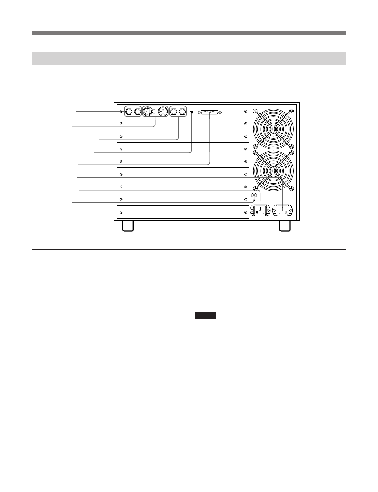
1REF IN (基準ビデオ信号入力)端子 (BNC型)
基準ビデオ信号を入力します。いずれか一方をループスルー出力
用に使用できます。ループスルー出力を使用しないときは、使用し
ない端子に市販の75Ω終端器を接続して終端してください。
2TC IN (タイムコード入力)端子 (XLR 3ピン)
タイムコード信号を入力します。いずれか一方をループスルー出力
に使用できます。
3VS BUS IN/OUT (VS-BUS入力/出力)端子 (BNC型)
VS-BUS用入力端子 (IN) とループスルー出力用端子 (OUT) で
す。ループスルー出力を使用しないときは、出力用端子に市販の
75Ω終端器を接続して終端してください。
4ADDRESS (アドレス)スイッチ (4連DIP)
システムに複数のSIU-80ユニットが存在する場合、本機のIDアド
レス (0〜15) を設定します。設定したアドレスは、主としてBKSI-
2040シリーズの通信アドレスとして使用されます。出荷時は0に設
定してあります。
◆ 設定のしかたなど詳しくは、BKSI-2040用ソフトウェア(BSS-100)のイン
ストレーションマニュアルをご覧ください。
2TC IN端子
8アース端子
1REF IN端子
3VS BUS IN/OUT端子
4ADDRESSスイッチ
5RS232C端子
6AC IN A端子
7AC IN B端子
5RS232C (データ通信用)端子 (D-sub 25ピン)
通信用入出力端子です。ソニーのISRソフトウェアをインストールし
たパーソナルコンピューターに接続して、本機および本機に装着し
た基板(BKSI-2070/2080を除く)の状態をモニターすることができ
ます。
ご注意
電源の故障をモニターするためには、電源ユニットが2台必要で
す。
6AC IN A (主電源用AC入力)端子 (3ピン)
別売りの電源コードセット(1-575-181-11) を接続します。
7AC IN B (バックアップ電源用AC入力)端子 (3ピン)
本機に別売りのバックアップパワーサプライBKSI-PS80を装着して
バックアップ電源として使用する場合、別売りの電源コードセット
(1-575-181-11) を接続します。
8信号アース端子
信号用のアース端子です。必要に応じて接地してください。
各部の名称と働き

7 (J)
一般
電源 AC100〜240V、50/60Hz
消費電流 5〜2A (最大負荷時)
供給可能最大電流 1.+5VDC:47A
2.−5.2VDC:20A
ただし、1と2の総和が52A以下のこと。
力率 98% (最大負荷時)
使用温度 5℃〜40℃
保存温度 −20℃〜+60℃
使用湿度 10%〜90% (ただし、結露しないこと)
質量 約18.5kg (オプションユニット含まず )
外形寸法 424×266×470mm
(幅/高さ/奥行き、最大突起部含まず)
入出力端子
REFIN BNC型 (×2、ループスルー出力付き)、
コンポジットビデオ信号:1.0Vp-p、75Ω
または
ブラックバースト信号
シンク、バースト:0.3Vp-p、75Ω
TCIN XLR3ピン、(メス×1、オス×1、ループス
ルー出力付き)、0.5〜18Vp-p、
10kΩ、平衡
VSBUSIN/OUT BNC型 (×2、ループスルー出力付き)、
1.3±0.3Vp-p、75Ω
RS232C D-sub25ピン、メス
付属品
ラックマウントアング ル ( 一 式 )
インストレーションマニュアル (1)
オペレーションマニュアル (1)
仕様および外観は、改良のため予告なく変更することがあります
が、ご了承ください。
別売アクセサリー
電源コードセット(1-575-181-11)
3極→2極変換プラグ(1-506-411-21)
バックアップパワーサプライBKSI-PS80
バックアップパワーサプライBKSI-PS80の仕様
電源 AC100〜240V、50/60Hz
消費電流 5〜2A (最大負荷時)
供給可能最大電流 1.+5VDC:47A
2.−5.2VDC:20A
ただし、1と2の総和が52A以下のこと。
力率 98% (最大負荷時)
使用温度 5℃〜40℃
保存温度 −20℃〜+60℃
使用湿度 10%〜90% (ただし、結露しないこと)
質量 約4kg
外形寸法 50×240×330mm
(幅/高さ/奥行き、最大突起部含まず。)
本機に装着可能な基板
ディスクコントロールボードBKSI-2010
ディスクコントローラーメモリーボードBKSI-2011
ビットレートリダクションエンコーダーボードBKSI-2020
オーディオエンコーダー8CHエクスパンジョンボードBKSI-2021
ビットレートリダクションデコーダーボードBKSI-2030
BRRデコーダージョグキットBKSI-2031
IDCCPUボードBKSI-2040
IDCシリアルリンクボードBKSI-2041
IDCシリアルI/FコネクターボードBKSI-2042
IDCパラレルI/FコネクターボードBKSI-2043
IDCS-BUSI/FコネクターボードBKSI-2044
アナログNTSC−4:2:2コンバーターボードBKSI-2050
4:2:2−アナログNTSCコンバーターボードBKSI-2060
オーディオ AD コンバーターボードBKSI-2070
オーディオ DA コンバーターボードBKSI-2080
仕様


1(E)
WARNING
To prevent fire or shock hazard, do not
expose the unit to rain or moisture.
To avoid electrical shock, do not open the
cabinet. Refer servicing to qualified
personnel only.
VORSICHT
Um Feuergefahr und die Gefahr eines elektrischen
Schlages zu vermeiden, darf das Gerät weder Regen noch
Feuchtigkeit ausgesetzt werden.
Um einen elektrischen Schlag zu vermeiden, darf das
Gehäuse nicht geöffnet werden. Überlassen Sie
Wartungsarbeiten stets nur einem Fachmann.
For the customers in USA
This equipment has been tested and found to comply with
the limits for a Class A digital device, pursuant to Part 15
of the FCC Rules. These limits are designed to provide
reasonable protection against harmful interference when
the equipment is operated in a commercial environment.
This equipment generates, uses, and can radiate radio
frequency energy and, if not installed and used in
accordance with the instruction manual, may cause
harmful interference to radio communications. Operation
of this equipment in a residential area is likely to cause
harmful interference in which case the user will be
required to correct the interference at his own expense.
You are cautioned that any changes or modifications not
expressly approved in this manual could void your
authority to operate this equipment.
The shielded interface cable recommended in this manual
must be used with this equipment in order to comply with
the limits for a digital device pursuant to Subpart B of Part
15 of FCC Rules.
This symbol is intended to alert the user to
the presence of important operating and
maintenance (servicing) instructions in the
literature accompanying the appliance.
WARNING: THIS WARNING IS APPLICABLE FOR USA
ONLY.
If used in USA, use the UL LISTED power cord specified
below.
DO NOT USE ANY OTHER POWER CORD.
Plug Cap Parallel blade with ground pin
(NEMA 5-15P Configuration)
Cord Type SJT, three 16 or 18 AWG wires
Length Less than 2.5 m (8 ft 3 in)
Rating Minimum 10 A, 125 V
WARNING: Using this unit at a voltage other than 120V
may require the use of a different line cord or
attachment plug, or both. To reduce the risk
of fire or electric shock, refer servicing to
qualified service personnel.
For the customers in the United Kingdom
WARNING
THIS APPARATUS MUST BE EARTHED.
IMPORTANT
The wires in this mains lead are coloured in accordance
with the following code:
Green-and-yellow: Earth
Blue: Neutral
Brown: Live
As the colours of the wires in the mains lead of this
apparatus may not correspond with the coloured markings
identifying the terminals in your plug proceed as follows:
The wire which is coloured green-and-yellow must be
connected to the terminal in the plug which is marked by
the letter E or by the safety earth symbol Yor coloured
green or green-and-yellow.
The wire which is coloured blue must be connected to the
terminal which is marked with the letter N or coloured
black.
The wire which is coloured brown must be connected to
the terminal which is marked with the letter L or coloured
red.
English

2(E)
For the customers in Europe
WARNING
This is a Class A product. In a domestic environment, this
product may cause radio interference in which case the
user may be required to take adequate measures.
Pour les utilisateurs en Europe
AVERTISSEMENT
Il s’agit d’un produit de Classe A. Dans un environnement
domestique, cet appareil peut provoquer des
interférences radio, dans ce cas l’utilisateur peut être
amené à prendre des mesures appropriées.
Per gli acquirenti in Europa
ATTENZIONE
Questo è un apparecchio di classe A e come tale, in un
ambiente domestico, può causare interferenze radio.
É necessario quindi che l’utilizzatore adotti gli
accorgimenti adeguati.
Para los clientes de Europa
ADVERTENCIA
Éste es un producto de clase A. En un ambiente
doméstico, este producto puede causar interferencias
radioeléctricas, en cuyo caso el usuario puede tener que
tomar las medidas adecuadas.
Für Kunden in Europa
Warnung
Dies ist eine Einrichtung, welche die Funk-Entstörung
nach Klasse A besitzt. Diese Einrichtung kann im
Wohnbereich Funkstörungen verursachen; in diesem Fall
kann vom Betreiber verlangt werden, angemessene
Maßnahmen durchzuführen und dafür aufzukommen.
Für Kunden in Deutschland
Dieses Gerät ist nur für den Gebrauch in Gewerbe und
Leichtindustrie bestimmt. Es entspricht der Klasse A, es
erfüllt nicht die Grenzwerte der Klasse B. In Deutschland
muß der Erwerber eine spezielle Betriebserlaubnis bei der
zuständigen Außenstelle des BAPT beantragen, um
dieses Gerät betreiben zu dürfen.
Attention – when the product is installed in rack:
1. Prevention against overloading of branch circuit
When this product is installed in a rack and is supplied
power from an outlet on the rack, please make sure
that the rack does not overload the supply circuit.
2. Providing protective earth
When this product is installed in a rack and is supplied
power from an outlet on the rack, please confirm that
the outlet is provided with a suitable protective earth
connection.
3. Internal air ambient temperature of the rack
When this product is installed in a rack, please make
sure that the internal air ambient temperature of the
rack is within the specified limit of this product.
4. Prevention against achieving hazardous condition
due to uneven mechanical loading
When this product is installed in a rack, please make
sure that the rack does not achieve hazardous
condition due to uneven mechanical loading.

3(E)
Table of Contents
Precautions ........................................................................................... 4(E)
Overview............................................................................................... 5(E)
Location and Function of Parts.......................................................... 6(E)
Front Panel ......................................................................................6(E)
Rear Panel........................................................................................7(E)
Specifictations ...................................................................................... 9(E)

4(E)
Precautions
Do not remove cover or attempt
to modify unit
Removing the cover of the unit or attempting to
modify the unit can cause electrical shock. Always
contact qualified service personnel for maintenance
and repairs.
Keep water and foreign objects
out of the unit
Water or foreign objects entering the unit can cause a
fire.
If water or foreign objects get inside the unit, turn the
unit off immediately. Disconnect the power cord and
contact a Sony representative or the dealer where you
purchased the unit.
Use the specified power cord
only
Use of another power cord can result in a fire or
electrical shock.
Do not damage the power cord
A damaged power cord can cause a fire or electrical
shock.
•Do not modify or damage the power cord.
•Do not place or drop heavy objects on the power
cord.
•Keep the power cord away from heat and heaters.
•When unplugging the power cord, always grasp by
the plug. Do not grasp the cord itself.
If the power cord should be damaged, contact qualified
service personnel for a replacement.
Do not install or use the unit in
humid or dusty locations
Dust, soot, and oil particles in the ambient atmosphere
can result in a fire or electrical shock.
Supply power of the specified
voltage
The specified voltages are indicated on the unit. Use
with other voltages can result in a fire or electrical
shock.
Do not block ventilation
If the ventilation slots are blocked, overheating inside
the unit can cause a fire. Observe the following points
for proper ventilation.
•Install at least 10 cm away from walls.
•Do not install in narrow or sealed locations.
•Do not install over carpets or other shaggy fabrics.
•Do not wrap with fabrics or other materials.
•Do not install the unit vertically, upside down, or on
its side.
Install in stable location
Installation on unstable or tilting surfaces can cause
the unit to fall off, resulting in injury.
Ground the unit safely
Failure to ground the unit can result in electrical shock.
If the unit cannot be grounded safely, contact a Sony
representative or the dealer where you purchased the
unit.
Discontinue use if a fan stops
If a fan stops, the status indicators either light red or
light alternating in color between red and green. If you
continue to use the unit in this state, overheating inside
the unit can cause a fire. If a fan has stopped, contact a
Sony representative or the dealer where you purchased
the unit.

5(E)
Overview
The SIU-80 is a system interface unit in which you can install various
signal processing boards needed to configure an A/V server system. The
unit has the following features.
Eight slots for installing optional boards
The units has eight slots for installing optional boards. They allow you to
install an appropriate combination of the following boards for controlling
disk drive units or for processing various signals.
•BKSI-2010 Disk Control Board
•BKSI-2020 Bit Rate Reduction Encoder Board
•BKSI-2030 Bit Rate Reduction Decoder Board
•BKSI-2040 IDC CPU Board
•BKSI-2050 Analog NTSC-4:2:2 Converter Board
•BKSI-2050P Analog PAL-4:2:2 Converter Board
•BKSI-2060 4:2:2-Analog NTSC Converter Board
•BKSI-2060P 4:2:2-Analog PAL Converter Board
•BKSI-2070 Audio AD Converter Board
•BKSI-2080 Audio DA Converter Board
Board control by BKSI-2040
When the BKSI-2040 is installed in the unit, it can control other boards
installed in the unit via a VS-BUS.
Power supply with high power factor
A power factor improvement circuit is employed, realizing a power factor
of 98% (at maximum load) and reducing the generation of harmonic
currents in the power supply.
Backup power supply
You can install the BKSI-PS80 Backup Power Supply in the unit to enable
the unit to continue operation even when the main power supply fails.
Built-in sync signal generator
A built-in sync signal generator provides various clock signals locked to an
external reference video signal for audio and video signals to be input to
the boards installed in the unit. When no external reference video signal is
input, the built-in sync generator generates the clock signals.
Built-in time code reader
A built-in time code reader allows an external time code to be provided for
the boards installed in the unit.
ISR (Interactive Status Reporting) support
The state of the unit as well as the boards (excluding the BKSI-2070/2080)
installed in the unit can be monitored from a personal computer via an RS-
232C cable.
Mountable in standard 19-inch rack
The unit can be mounted in an EIA standard 19-inch rack.

6(E)
Location and Function of Parts
This section describes the functions of the parts on the front and rear
panels of the unit.
For how to install optional boards and the optional BKSI-PS80 Backup Power
Supply in the unit, refer to the Installation Manual supplied with the unit.
Front Panel
Indication
1POWER A (main power) switch
Press the side of the switch marked “1” to turn the unit
on, and press the side marked “¬” to turn the unit off.
2POWER B (backup power) switch
This switch is provided on units with the optional
BKSI-PS80 Backup Power Supply installed. Turn it on
or off in the same way as the POWER A switch. When
using a BKSI-PS80, keep this switch on.
3Status indicator A
This indicator lights when the POWER A switch is
turned on. When the unit is in normal condition, it
stays lit green. If the unit develops a fault, it indicates
the fault as described in the table at the right.
BA
3Status indicator A
4Status indicator B
1POWER A switch
2POWER B switcha)
a) Provided only for the SIU-80 with the
optional BKSI-PS80 installed.
Lights red.
Lights, alternating in
color between red
(longer duration)
and green (shorter
duration).
For SIU-80 with
one power
supply unit
Fault
Power supply
cooling fan
stopped.
• Either of the two
chassis fans
stopped.
• No –5.2V power
supply
For SIU-80 with
two power
supply units
• Power supply
cooling fan
stopped.
• No –5.2V power
supply
Either of the two
chassis fans
stopped.
Lights, alternating in
color between green
(longer duration)
and red (shorter
duration).
• There is no
reference video
signal input.
• No –5.2V power
supply
There is no
reference video
signal input.
Goes off. • No +5V power
supply
• The POWER
switch is off.
• No +5V power
supply
• The POWER
switch is off.

7(E)
4Status indicator B
This indicator lights when the POWER B switch is
turned on. When the unit is in normal condition, it
stays lit green. If the unit develops a fault, it indicates
the fault as described in the table on the previous page.
Rear Panel
1REF IN (reference video signal input)
connectors (BNC type)
Connect a reference video signal to one of these
connectors. You can use the other one for loop-through
output. When not using the loop-through output,
terminate the unused connector with a 75-ohm
terminator (not supplied).
2TC IN (time code input) connectors (XLR 3-pin)
Connect a time code signal to one of these connectors.
You can use the other one for loop-through output.
3VS BUS IN/OUT (VS-BUS input/output)
connectors (BNC type)
Connect a VS-BUS to these connectors. The IN
connector is for signal input and the OUT connector is
for loop-through output.When not using the loop-
through output, terminate the OUT connector with a
75-ohm terminator (not supplied).
4ADDRESS switch (4-switch DIP)
When the system incorporates more than one SIU-80
unit, use this switch to set the unit’s ID address (0 to
15). The ID address is used mainly when BKSI-2040
series boards installed in the unit engage in data
communications with other units. When the unit is
shipped, this switch is set to 0.
For more information about setting the ID address, refer to
the installation manual supplied with the software (BSS-
100) to be installed in the BKSI-2040.
1REF IN connectors
2TC IN connectors
3VS BUS IN/OUT connectors
4ADDRESS switch
5RS232C connector
6AC IN A connector
7AC IN B connector
8Ground terminal

8(E)
5RS232C (data communication) connector (D-sub
25-pin)
Use this connector for data communications. When a
personal computer in which Sony ISR software is
installed is connected to this connector, you can use
the software to monitor the state of the unit as well as
the boards (excluding the BKSI-2070/2080) installed
in the unit.
Note
Monitoring power supply faults requires the unit to be
provided with two power supply units.
6AC IN A (AC input for main power supply)
connector (3-pin)
Connect to an AC power outlet using an appropriate
power cord.
7AC IN B (AC input for backup power supply)
connector (3-pin)
When using the unit with the optional BKSI-PS80
Backup Power Supply installed, connect this connector
to an AC power outlet using an appropriate power
cord.
8Signal grounding terminal
Connect this terminal to the ground as necessary.
Location and Function of Parts

9(E)
Specifications
General
Power requirements
100 to 240 V AC, 50/60 Hz
Current consumption
5 A to 2 A (at maximum load)
Supplied current 1. +5 V DC: 47A
2. –5.2 V DC: 20A
The sum of 1 and 2 must not
exceed 52 A.
Power factor 98% (at maximum load)
Operating temperature
5˚C to 40˚C (41˚F to 104˚F)
Storage temperature
–20˚C to +60˚C (–4˚F to +140˚F)
Operating humidity10% to 90% (Condensation not
allowed)
Mass About 18.5 kg (40 lb 12 oz)
(excluding optional boards and
units)
Dimensions 424 ×266 ×470 mm
(16 3/4×10 1/2×18 5/8inches)
(w/h/d, excluding protruding
parts)
Input/Output connectors
REF IN BNC type (2, loop-through)
Composite video signal: 1.0 Vp-p,
75 ohms
or
Black burst signal
Sync, Burst: 0.3 Vp-p, 75 ohms
TC IN XLR 3-pin (2, female and male,
loop-through)
0.5 to 18 Vp-p, 10 kilohms,
balanced
VS BUS IN/OUT BNC type (2, loop-through)
1.3 ±0.3 Vp-p, 75 ohms
RS232C D-sub 25-pin, female
Supplied accessories
Rack mount angles (1 set)
Installation Manual (1)
Operation Manual (1)
Design and specifications are subject to change
without notice.
Optional accessory
BKSI-PS80 Backup Power Supply
specifications
Power requirements
100 to 240 V AC, 50/60 Hz
Current consumption
5 A to 2 A (at maximum load)
Supplied current 1. +5 V DC: 47A
2. –5.2 V DC: 20A
The sum of 1 and 2 must not
exceed 52 A.
Power factor 98% (at maximum load)
Operating temperature
5˚C to 40˚C (41˚F to 104˚F)
Storage temperature
–20˚C to +60˚C (–4˚F to +140˚F)
Operating humidity10% to 90% (Condensation not
allowed)
Mass About 4 kg (8 lb 13 oz)
Dimensions 50 ×240 ×330 mm
(2 ×9 1/2×13 inches)
(w/h/d, excluding protruding
parts)
Optional boards
BKSI-2010 Disk Control Board
BKSI-2011 Disk Controller Memory Board
BKSI-2020 Bit Rate Reduction Encoder Board
BKSI-2021 Audio Encoder 8ch Expansion Board
BKSI-2030 Bit Rate Reduction Decoder Board
BKSI-2031 BRR Decoder Jog Kit
BKSI-2040 IDC CPU Board
BKSI-2041 IDC Serial Link Board
BKSI-2042 IDC Serial I/F Connector Board
BKSI-2043 IDC Parallel I/F Connector Board
BKSI-2044 IDC S-BUS I/F Connector Board
BKSI-2050 Analog NTSC-4:2:2 Converter Board
BKSI-2050P Analog PAL-4:2:2 Converter Board
BKSI-2060 4:2:2-Analog NTSC Converter Board
BKSI-2060P 4:2:2-Analog PAL Converter Board
BKSI-2070 Audio AD Converter Board
BKSI-2080 Audio DA Converter Board

This manual suits for next models
1
Table of contents
Other Sony Power Supply manuals