Sungrow IDC30E User manual

IDC30EDC
ChargerUser ManualIDC30E-UEN-
Ver13-202307
User Manual
DC Charger
IDC30E
IDC30E-UEN-Ver13-202307


I
All Rights Reserved
All Rights Reserved
No part of this document can be reproduced in any form or by any means without the prior
written permission of Sungrow Power Supply Co., Ltd (hereinafter "SUNGROW").
Trademarks
and other Sungrow trademarks used in this manual are owned by
SUNGROW.
All other trademarks or registered trademarks mentioned in this manual are owned by their
respective owners.
Software Licenses
• It is prohibited to use data contained in firmware or software developed by SUNGROW,
in part or in full, for commercial purposes by any means.
• It is prohibited to perform reverse engineering, cracking, or any other operations that
compromise the original program design of the software developed by SUNGROW.
Privacy Protection
• Information contained in this manual is the private property of Sungrow Power Supply
Co., Ltd. Internal reproduction is allowed only for product evaluation or other appropriate
purposes.
• We declare that the network account and password data stored in the equipment system
are only used for remote control and monitoring of the equipment and will not be trans-
mitted to any third-party data platform without your permission.
Disposal
After the service life of the charger ends, please dispose of it in accordance with the applica-
ble electrical waste disposal act at the installation location. It can also be returned to Sun-
grow, but the relevant expenses shall be borne by your party.

II
About This Manual
The manual mainly contains product information, as well as guidelines for installation, opera-
tion, and maintenance.
Target Group
This manual is intended for professional technicians who are responsible for installation, op-
eration, and maintenance of the charger, and users who need to check charger parameters.
A professional technician is required to meet the following requirements:
• Know electronic, electrical wiring, and mechanical expertise, and be familiar with electri-
cal and mechanical circuit diagrams.
• Have received professional training related to installation and commissioning of electrical
equipment.
• Be able to quickly respond to hazards or emergencies that occur during installation and
commissioning.
• Be familiar with local standards and relevant safety regulations of electrical systems.
• Read this manual thoroughly and understand the safety instructions related to
operations.
EMC
In some cases, even if the equipment is in accordance with the standard emission limits, it
can have an impact in certain application areas (some sensitive equipment is placed in the
same location; the equipment is installed close to a radio or TV receiver), and the operator
shall take appropriate action to correct this situation.
How to Use This Manual
Please read this manual carefully before using the product and keep it properly at a place
for easy access.
All contents, pictures, marks, and symbols in this manual are owned by SUNGROW. No part
of this document may be reprinted by the non-internal staff of SUNGROW without written
authorization.
Contents of this manual may be periodically updated or revised, and the actual product pur-
chased shall prevail. Users can obtain the latest manual from support.sungrowpower.com
or sales channels.

III
Contents
All Rights Reserved .....................................................................................................I
About This Manual......................................................................................................II
1 Safe Instructions ...............................................................................................1
1.1 Symbols ........................................................................................................1
1.2 Packaging, Shipping and Storage ....................................................................2
1.3 Operations.....................................................................................................3
1.4 Maintenance and Replacement .......................................................................4
2 Product Introduction .........................................................................................5
2.1 Introduction....................................................................................................5
2.2 Production Introduction ...................................................................................6
2.2.1 Appearance and Dimensions .................................................................6
2.2.2 Internal Structure ..................................................................................6
2.2.3 External Port.........................................................................................7
2.2.4 LED Indicator Signals ............................................................................8
2.3 Unpacking and Storage...................................................................................8
2.3.1 Unpacking and Inspection......................................................................8
2.3.2 Packing list ...........................................................................................9
2.3.3 Storage ..............................................................................................10
2.4 Installation ................................................................................................... 11
2.4.1 Safety ................................................................................................ 11
2.4.2 Installation Tools .................................................................................12
2.4.3 Installation Clearance..........................................................................13
2.4.4 Pre-installation Preparation..................................................................14
2.4.4.1 RCD Requirements....................................................................14
2.4.4.2 AC Input Cable..........................................................................15
2.4.4.3 OT terminal ...............................................................................15
2.4.4.4 Ethernet Cable Requirements.....................................................15
2.4.4.5 SIM Card Requirements.............................................................15
2.4.5 Wall-Mounted Installation.....................................................................15
2.4.5.1 Install the Wall-Mounting Bracket ................................................15
2.4.5.2 Install Charger Brackets .............................................................16

IV
2.4.5.3 Install the Handles .....................................................................16
2.4.5.4 Charger Installation....................................................................17
2.4.5.5 Remove the Handles .................................................................17
2.4.5.6 Secure the Charger ...................................................................18
2.4.5.7 Install the Charging Connector Socket.........................................18
2.4.5.8 Connect the Cable Connection Terminal......................................19
2.4.5.9 Ethernet Cable Connection.........................................................22
2.4.5.10 SIM Card Installation................................................................23
2.4.6 Pole-mounted Installation (Optional).....................................................23
2.4.6.1 Pole Components ......................................................................24
2.4.6.2 Recommended Construction Scheme for Charger
Foundation .............................................................................25
2.4.6.3 Remove the Cover Plate ............................................................25
2.4.6.4 Install the Mounting Pole ............................................................26
2.4.6.5 Install the Handles .....................................................................27
2.4.6.6 Charger Installation....................................................................27
2.4.6.7 Detach the Handles ...................................................................28
2.4.6.8 Install the Charger Connector Socket .........................................28
2.4.6.9 Connect the AC Cable ...............................................................29
2.4.6.10 Install the Cover Plate ..............................................................30
2.4.6.11 Charger Connector Installation..................................................30
2.4.7 Movable Charger Installation (Optional) ................................................31
3 Interface Function Description .....................................................................34
3.1 Page Introduction .........................................................................................34
3.1.1 System Check ....................................................................................34
3.1.2 Start Page ..........................................................................................34
3.1.3 Other Pages .......................................................................................35
3.1.3.1 Unavailable..............................................................................36
3.1.3.2 Emergency Stop........................................................................37
3.1.3.3 Firmware Update.......................................................................39
3.1.3.4 Offline.......................................................................................40
3.1.3.5 Abnormal ..................................................................................40
3.1.3.6 Language Settings.....................................................................41
3.2 Charging .....................................................................................................42
3.2.1 Plug the Charging Connector ...............................................................42
3.2.2 Charging Method ................................................................................43
3.2.2.1 Charging via RFID Card .............................................................43
V
3.2.2.2 Plug&Play .................................................................................48
4 Operation and Maintenance Mode ..............................................................50
4.1 Login and Logout..........................................................................................51
4.1.1 Login..................................................................................................51
4.1.2 Logout................................................................................................52
4.2 Function Description .....................................................................................52
4.2.1 CCU Info ............................................................................................52
4.2.2 Version...............................................................................................56
4.2.3 Config_1 ............................................................................................57
5 Faults and Troubleshooting ..........................................................................61
5.1 TCU ............................................................................................................61
5.2 CCU ............................................................................................................65
5.3 LLC .............................................................................................................67
5.4 PFC.............................................................................................................71
5.5 Charging Stop Code .....................................................................................75
6 Maintenance Instructions ..............................................................................82
7 Appendix ..........................................................................................................84
7.1 System Parameters ......................................................................................84
7.2 Quality Assurance ........................................................................................85
7.3 Contact Information ......................................................................................86


1
1 Safe Instructions
1.1 Symbols
This manual contains important safety instructions, which are highlighted with the following
symbols, to ensure personal and property safety during usage, or to help optimize the prod-
uct performance efficiently.
Indicates high-risk potential hazards that, if not avoided, may lead to death or seri-
ous injury.
Indicates potential moderate-risk potential hazards that, if not avoided, may lead to
death or serious injury.
Indicates potential low-risk potential hazards that, if not avoided, may lead to minor
or moderate injury.
Indicates potential risks that, if not avoided, may lead to device malfunction or fi-
nancial losses.
“NOTE” indicates additional information, emphasized content, or tips that may
help you solve problems or save time.
Please pay attention to the danger warning signs on the machine body at all times. The
signs include:

2
table 1-1 Symbols description
Symbols Description
Operation by qualified personnel only.
The temperature here is higher than the acceptable range for the
human body. Do not touch it without protection.
Please read the manual before any operation.
Hazardous voltage still exists after the device stops. Do not con-
duct any operation on the device immediately. Wait for at least 10
minutes.
1.2 Packaging, Shipping and Storage
Packaging
The charger is wrapped tightly with wire drawing film and protected by foam
blocks. It is packed in cardboard and underpinned by a wooden bottom base.
Shipping
During shipping, the charger shall be packed firmly and intact with cardboard and
wooden bottom support, the loading and unloading directions are clearly marked,
and the charger shall not be stored and shipped upside down.
During transport, make sure that the equipment is firmly fixed in order to avoid vio-
lent shaking and bumps that damage the packaging and its content.
After arrival of goods, check for transport damage and, if any, contact the shipping
company or SUNGROW.
Check if the content inside the package matches the delivery list.
Non-professional personnel shall not disassemble the components.
1 Safe Instructions User Manual

3
Storage
The device shall be stored in a dry, clean, and well-ventilated place, free from harm-
ful gases.
Storage temperature: -40℃~+70℃
Ambient temperature at startup: -35℃~+55℃
Ambient temperature at full power: -25℃~+50℃
Relative humidity: 5%~95% non-condensing
Do not store it near corrosive articles.
1.3 Operations
High voltages are present during operation and could cause electrical shock, re-
sulting in death, serious personal injury, or serious property damage. Follow the
safety instructions listed in this manual and other relevant documentation.
When the device is working, the temperature around the heat dissipation air outlet
is high and there is a risk of burns. Please do not touch it.
When operating the device, local regulations and specifications shall be observed.
No extension cables shall be used when connecting an electric vehicle to an elec-
tric vehicle power supply device.
Only connect electric vehicles and their charging equipment. Do not connect any
other loads (electric tools, etc.).
After charging, please put the charging connector back into the connector socket
to prevent unnecessary exposure to contamination or moisture.
Do not bend, squeeze or roll the charging connector to avoid mechanical damage.
Do not expose the surfaces of the charger to heat, dirt, or water.
It is strictly prohibited to use the charger when the charging connector or the
charging cable is defective, appears cracked, frayed, broken, or otherwise dam-
aged. If any anomaly is found, please, refer to the seller or SUNGROW
If there is any abnormality during use, please press the emergency stop button im-
mediately to cut off the power supply.
In case of a thunderstorm, please charge carefully.
Children shall not approach or use the charger during the charging process to
avoid injury.
During a thunderstorm, please, charge carefully and be aware of the potential risks.
When charging an electric vehicle with a charger, read carefully the relevant tips
and instructions of the vehicle.
User Manual 1 Safe Instructions

4
1.4 Maintenance and Replacement
High voltages are present during operation and could cause electrical shocks, re-
sulting in death, serious personal injury, or serious property damage. Before any
maintenance work, the device must be powered off and operated in strict accord-
ance with the safety precautions listed in this manual and other relevant
documentation.
Maintain the equipment, only once you have familiarized yourself with the contents
of this manual and with suitable tools and test equipment.
Before performing maintenance work, power down the device and wait at least 10
minutes before operating the device.
During maintenance, avoid the presence of unrelated persons at the maintenance
site, and place temporary to warn signs or barriers to isolate them.
Do not power the device until you have confirmed that any faults affecting the safe
performance of the device have been removed.
Observe the ESD protection specifications during maintenance.
Keep the charging connector clean and dry, and wipe it with a clean, dry cloth if it
is dirty. Do not touch the charging connector’s pins with your hands while it is on.
It is necessary to regularly check whether there is damage to the connector, and
check whether the enclosure and surrounding components have visible signs of
damage. (Visual inspection)
1 Safe Instructions User Manual

5
2Product Introduction
2.1 Introduction
The 30kW DC charger (hereinafter “Charger”) is used for DC charging of electric vehicles
(EVs) and can be wall-mounted, pole-mounted, or cart-mounted, with the following
advantages:
Technology leadership
Adopting the world's leading power supply technology and design concept, the charger is
designed to provide safe, reliable, and controllable DC power for electric vehicles.
Enhanced features
It is featured active power correction, high efficiency, high power density, high reliability, ul-
tra-low standby power consumption, intelligent control, and excellent human-computer inter-
action experience.
Future-proofed
With ultra-wide constant power output voltage, it can support all electric vehicles in the mar-
ket and meets their charging needs.

6
2.2 Production Introduction
2.2.1 Appearance and Dimensions
figure 2-1 Product Dimensions (in mm)
2.2.2 Internal Structure
figure 2-2 Diagram of the Internal Structure
table 2-1 Internal Structure Description
No. Name
A Door sensor
B Axial flow fan
C Insulation Monitor
D CCU(Charge Control Unit) module
2 Product Introduction User Manual

7
No. Name
E DC Meter
F AC input connection terminal
G Charging connector
H TCU(Tariff and Control Unit) module
I Display
J Card Reader
K Lamp panel
2.2.3 External Port
figure 2-3 Diagram of Bottom Terminals
table 2-2 Description of Bottom Terminals
No. Name
A DC charger cable outlet
B Air outlet
C RSVD port
D LAN port
E AC cable inlet
F 4G & WiFi antenna
User Manual 2 Product Introduction

8
2.2.4 LED Indicator Signals
table 2-3 Indicator status
The indi-
cator
color
Indicator Effect Re-
marks Meaning
Blue
indicator
Blue indicator is constantly on Normal
Fully charged(include the
charging connector is con-
nected to but not charge
the vehicle)
Blue indicator flashes, on for 1s
and off for 1s; circulating Normal Charging
Red
indicator Red indicator is constantly on Abnor-
mal Fault
Green
indicator Green indicator is constantly on Normal Standby
2.3 Unpacking and Storage
2.3.1 Unpacking and Inspection
Each device is thoroughly tested and carefully inspected before delivery. Nonetheless, dam-
age may still occur during shipping. For this reason, please conduct a thorough inspection of
the device.
• Check the packaging case for any visible damage.
• Check to make sure that the scope of delivery matches the packing list.
• Check the inner contents for damage after unpacking.
Contact SUNGROW or the transport company in case of any damage or mismatches and
provide photos to facilitate services.
Do not dispose of the original packing case. It is recommended to store the device in original
packing case when the device is decommissioned.
After receiving the product, check whether the appearance and structural parts of
the device are damaged, and check whether the packing list is consistent with the
actual ordered product.
If there are problems with the above inspection items, do not install the device and
contact SUNGROW as soon as possible.
If cutters is uses for unpacking, be careful not to damage the charger.
2 Product Introduction User Manual

10
No. Name Unit No.
E IDC30E socket-outlet trim PCS 1
F IDC30E socket-outlet trim B PCS 1
GExpansion bolt PCS 6
H M1 card PCS 2
IWall-mounted components-upper left PCS 1
JWall-mounted components-upper right PCS 1
KWall-mounted components-lower left PCS 1
LWall-mounted components-lower right PCS 1
M Montmorillonite desiccant PCS 1
NHexalobular socket pan head tamper proof screws
M5X12, SUS304 PCS 20
OHexalobular socket countersunk head tamper proof
screws M4X12, SUS304 PCS 1
PModular RJ45 plug PCS 2
QKeys PCS 2
RCertificate of Conformity PCS 1
STest report PCS 1
2.3.3 Storage
Proper storage is required if the charger is not to be installed immediately.
• Store the charger in the original packing case with the desiccant inside.
• The storage temperature must be always between -40℃and﹢70℃, and the storage rela-
tive humidity must be always between 5% and 95%, non-condensing.
• In case of stacking storage, the number of stacking layers should never exceed the limit
marked on the outer side of the packing case.
• The packing case should be upright.
• If the charger needs to be transported again, pack it tightly before loading and transport-
ing it.
• Do not store the charger in places with items that may affect or damage the charger.
• Store the charger in a clean and dry place to prevent dust and water vapor exposure.
• Do not store the charger in places with corrosive substances or susceptible to rodents
and insects.
• Carry out periodic inspections. If any insect or rodent bites are found, replace the pack-
aging materials in due time.
2 Product Introduction User Manual

11
• If the charger has been stored for more than a year, inspection and testing by professio-
nals are required before it can be put into operation.
Please store the charger according to the storage requirements. Product damage
caused by failure to meet the storage requirements is not covered by the warranty.
2.4 Installation
Respect all local standards and requirements during mechanical installation.
2.4.1 Safety
Make sure there is no electrical connection before installation.
In order to avoid electric shock or other injury, make sure that holes will not be
drilled through and interrupting any electricity or plumbing installations.
Poor installation environment will affect system performance!
Install the charger in a well-ventilated place.
Ensure that the heat dissipation system or vents are not blocked.
Do not install the charger in an environment with smoke, flammable and explosive
objects.
Improper handling may cause personal injury!
When moving the charger, be aware of its weight and keep the balance to prevent it
from tilting or falling.
Wear proper protective equipment before performing operations on the charger.
User Manual 2 Product Introduction
Other manuals for IDC30E
1
Table of contents
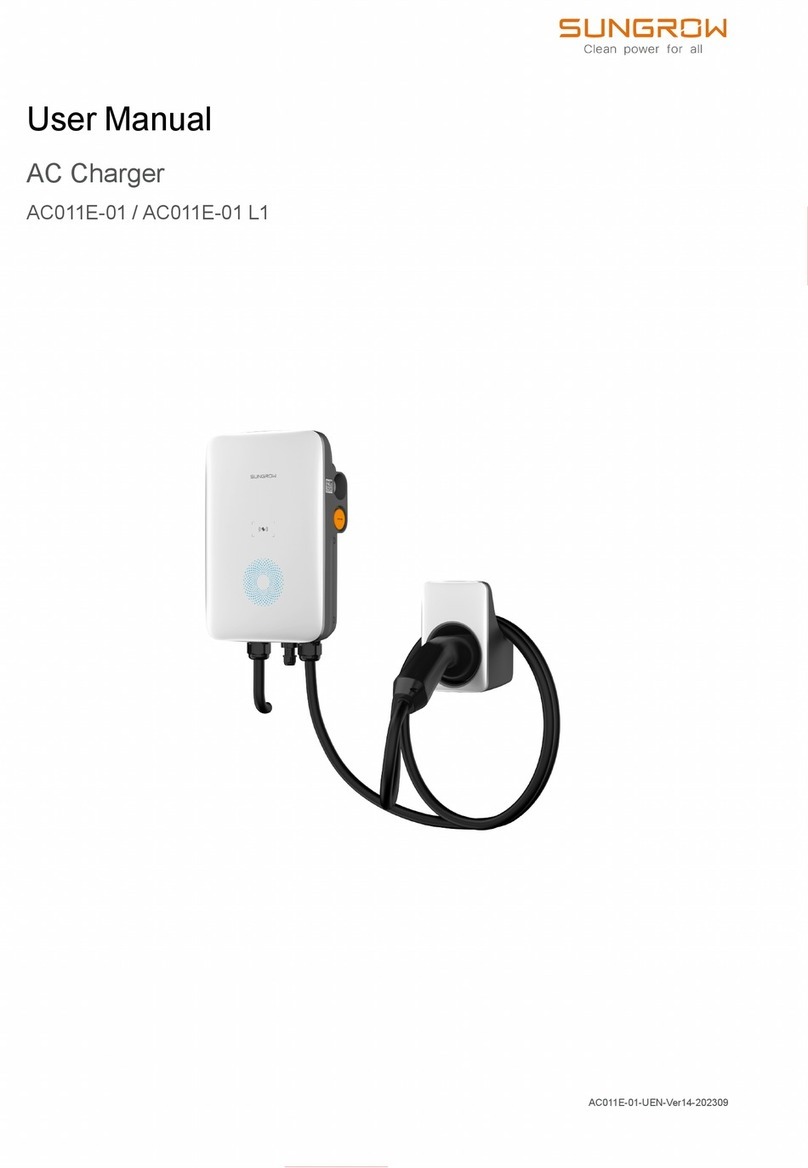
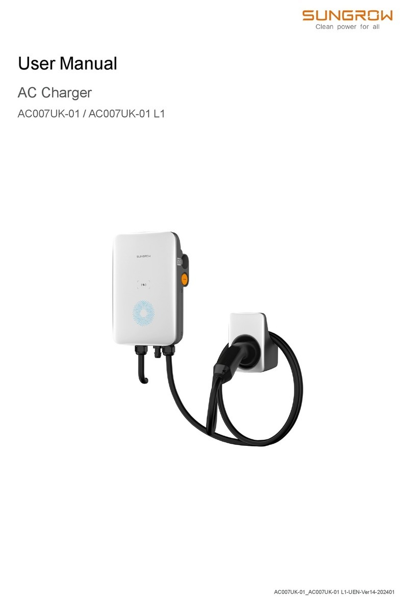
Other Sungrow Batteries Charger manuals

Sungrow
Sungrow AC011E-01 User manual

Sungrow
Sungrow AC011E-01 User manual

Sungrow
Sungrow AC011E-01 User manual

Sungrow
Sungrow AC011E-01 User manual

Sungrow
Sungrow AC011E-01 User manual

Sungrow
Sungrow AC007UK-01 User manual

Sungrow
Sungrow IDC30E User manual

Sungrow
Sungrow AC007E-01 User manual

Sungrow
Sungrow AC007UK-01 L1 User manual

Sungrow
Sungrow AC011E-01 User manual