r.fK/CKER{fK/CKER{fK/CKER{fK/CKER{fK/CKER{fK/CKER{fK/CKER{fK/CKER(fKJCKER(fK/CKER(fK/CICER{f~
Sal
UMrrED
WARRANTY
rs
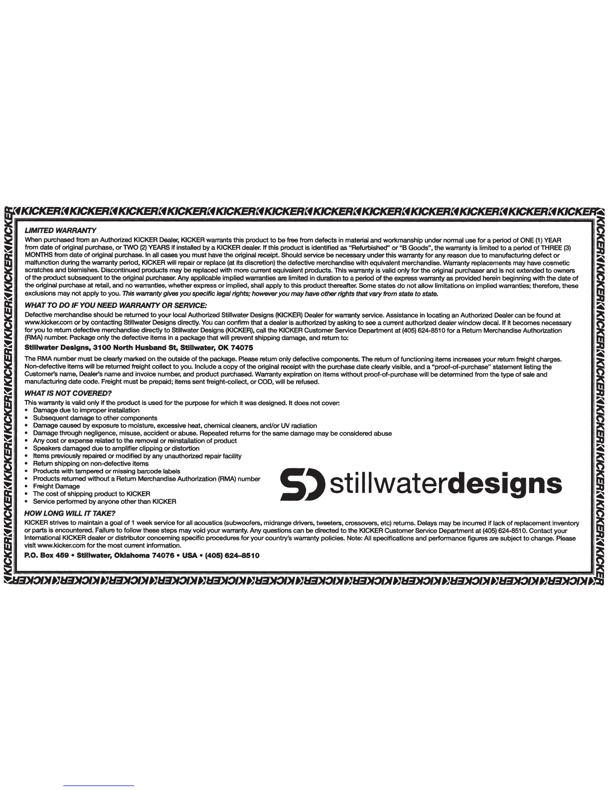
5( When purchased from an Authorized KICKER Dealer, KICKER warrants
this
product
to
be
free
from
defects
in material and
workmanship
under
nonnal
use
for
a period
of
ONE
(1)
YEAR
~
~
from
date
of
original purchase,
or
lWO
(2)
YEARS
if
installed
by
a KICKER dealer.
If
this
product
is identified
as
"Refurbished"
or
"B
Goods",
the
warranty
is
limited
to
a period
of
THREE
(3)
!il
mMONTHS
from
date
of
original purchase. In all cases
you
must
have
the
original receipt. Should service
be
necessary
under
this
warranty
for
any
reason
due
to
manufacturing
defect
or
II":~
malfunction during
the
warranty
period, KICKER will repair
or
replace (at its discretion)
the
defective
merchandise
with
equivalent merchandise. Warrantyreplacements
may
have
cosmetic
;
scratches
and
blemishes. Discontinued
products
may
be
replaced
with
morecurrent equivalent products. Thiswarranty
is
valid
only
for
the
original purchaser
and
is
not
extended
to
owners
~
g
of
the
product
subsequent
to
the
original purchaser.
Any
applicable implied warranties are limited in duration
to
a
period
of
the
express
warranty
as
provided herein beginning
with
the
date
of
~--,
5C
the
original purchase
at
retail,
and
no
warranties,
whether
express
or
implied,shall
apply
to
this
product
thereafter.
Some
states
do
not
allow
limitations
on
implied warranties; therefore.
these
m
~
exclusions
may
not
apply
to
you. This
wananty
gives
you
specificlegal rights; however
you
may
have
other
rights that
vaty
from state
to
state.
~
~
WHATTO
DO
IF
YOUNEED WARRANTYOR SERVICE:
41
J11
Defectivemerchandise
should
be
retumed
to
your
local
Authorized StiUwaterDesigns(KICKER)
Dealerfor
warrantyservice.
Assistance
in
locating
an Authorized Dealer
can
be
found at
~
K www.kicker.com
or
by
contacting
StillwaterDesigns directly. You
can
confinn
that
a dealeris authorized
by
asking
to
see
a current authorized
dealer
window
decal.
If
it
becomes
necessary n
ll5
for
you
to
return defectivemerchandise directly
to
StillwaterDesigns (KICKER), call
the
KICKER
Customer
Service Department
at
(405) 624-8510
for
a Return MerchandiseAuthorization ;
~
(RMA) number. Package
only
the
defective
items
in a
package
that
will prevent
shipping
damage,
and
return
to:
~
~
Stillwater
Designs,
3100
North
Husband
St,
Stillwater,
OK
74075
~
Jli
The
RMA
number
must
be
clearly marked
on
the
outside
of
the
package. Please return
only
defective
components.
The
return
of
functioning
items
increases
your
return freight charges.
...
5(
Non-defectiveitemswill
be
returned freight
collect
to
you.
Include
a
copy
of
the
original receipt
with
the
purchase
date
clearly visible,
and
a
"proof-of-purchase"
statement listing
the
Customer's name, Dealer's
name
and invoice number,
and
product
purchased. Warrantyexpiration
on
items
without
proof-of-purchase will
be
detennined
from
the
type
of
sale
and
manufacturing
date
code. Freight
must
be
prepaid;
items
sent
freight-collect,
or
COD, will
be
refused.
WHAT IS
NOT
COVERED?
This warranty is valid
only
if
the
product
is
used
for
the
purpose
for
which
it
was
designed.
It
does
not
cover:
• Damage
due
to
improper
installation
a
I
•
Subsequent
damage
to
other
components
• Damagecaused
by
exposure
to
moisture, excessive
heat,
chemical cleaners,
and/or
UVradiation
~
• Damagethrough negligence, misuse,
accident
or
abuse. Repeated returns
for
the
same
damage
may
be
considered
abuse
~..
· •
Any
cost
or
expense related
to
the
removal
or
reinstallation
of
product
• Speakers
damaged
due
to
amplifier
clipping
or
distortion .
• Items previously repaired
or
modified
by
any
unauthorized repairfacility
~
t\
• Return shipping
on
non-defective
items
~
• Products
with
tampered
or
missing
barcode
labels • •
~
:
~:~without
a
Retum
Men:handiseAuthorization
(RMA)
number
S''
stIllwaterd
es
Igns
It:
•
The
cost
of
sh1pp1ng
product
to
KICKER
~
~
I•
Service
perfonned
by
anyone
other
than KICKER
~
HOW
LONG WILL
ff
TAKE?
r5
KICKER strives
to
maintain a goal
of
1
week
service
for
all
acoustics
(subwoofers, midrangedrivers, tweeters, crossovers, etc) returns. Delays
may
be
incurred
if
lack
of
replacement inventory
~
~
or
parts is encountered. Failure
to
follow
these
steps
may
void
your
warranty. Any questions
can
be
directed
to
the
KICKER
Customer
Service
Department
at
(405) 624-8510.
Contact
your
S:t
~lfj
International KICKER dealer
or
distributor
concerning
specific
procedures
for
your
country'swarranty policies. Note: All specifications
and
perfonnance
figures are
subject
to
change. Please
41
visit www.kicker.com
for
the
most
current infonnation.
~
~
P.O.
Box
459
•
Stillwater,
Oklahoma
74076
• USA • (405)
624-8510
(IS
~~JJIEDKJDIJJIEDKJDIJJIEDI:JDIJJIEDKJDIJJIEDKJDIJ}IEDKJDIJ}IGDKJOIJJIEDKJDIJJlEDI:JDIJJIEDKJDIJJI:EDI:JD/Jij