Kicker QS60.2 User manual

QS
QSCOMPONENTSYSTEM
QS65.2
QS60.2
English Version
Versión Español
Sistema de altavoces componentes QS
Manual del Propietario
Deutsche Version
QS-Komponentensystem
Benutzerhandbuch
Version Française
Système à composants QS
Manuel d’utilisation
2009 QS Multilingual h01.indd 12009 QS Multilingual h01.indd 1 11/21/2008 10:54:11 AM11/21/2008 10:54:11 AM

2QSCOMPONENTSYSTEM
QSCOMPONENTSYSTEMOwner’sManual
QS COMPONENTS
The KICKER QS-series component systems offer unmatched audio fidelity for vehicle applications.
Whether you’re configuring the ultimate multi-speaker and subwoofer surround system or simply
upgrading from dull, lifeless factory speakers, the QS component systems deliver the most pleasing full-
range sound on the market today!
PERFORMANCE
Authorized KICKER Dealer:
Purchase Date:
Speaker Model Number:
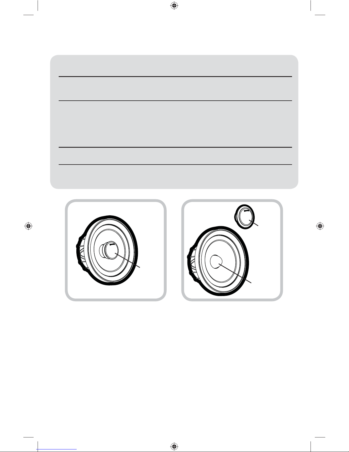
Model: QS60.2 QS65.2
Woofer Size 6” (160mm) 6.5” (165mm)
Tweeter Size 1-3/16” (30mm) 1-3/16” (30mm)
Dome Material Tetoron®Tetoron®
Impedance, (DC Resistance) 4Ω, (3.5Ω)4Ω, (3.5Ω)
Power Handling Peak, (RMS) 180W, (90W) 200W, (100W)
Sensitivity @ 1W, 1m 86dB 87dB
Effective Frequency Range 50Hz–22kHz 40Hz–22kHz
Woofer Mounting Hole Diameter 5-1/16” (129mm) 5-7/16” (138mm)
Woofer Mounting Depth ≤2.5” (63.5mm) ≤2.5” (63.5mm)
Tweeter Hole Diameter 1-13/16” (46mm) 1-13/16” (46mm)
Flush-mount Tweeter Depth 1-1/8” (29mm) 1-1/8” (29mm)
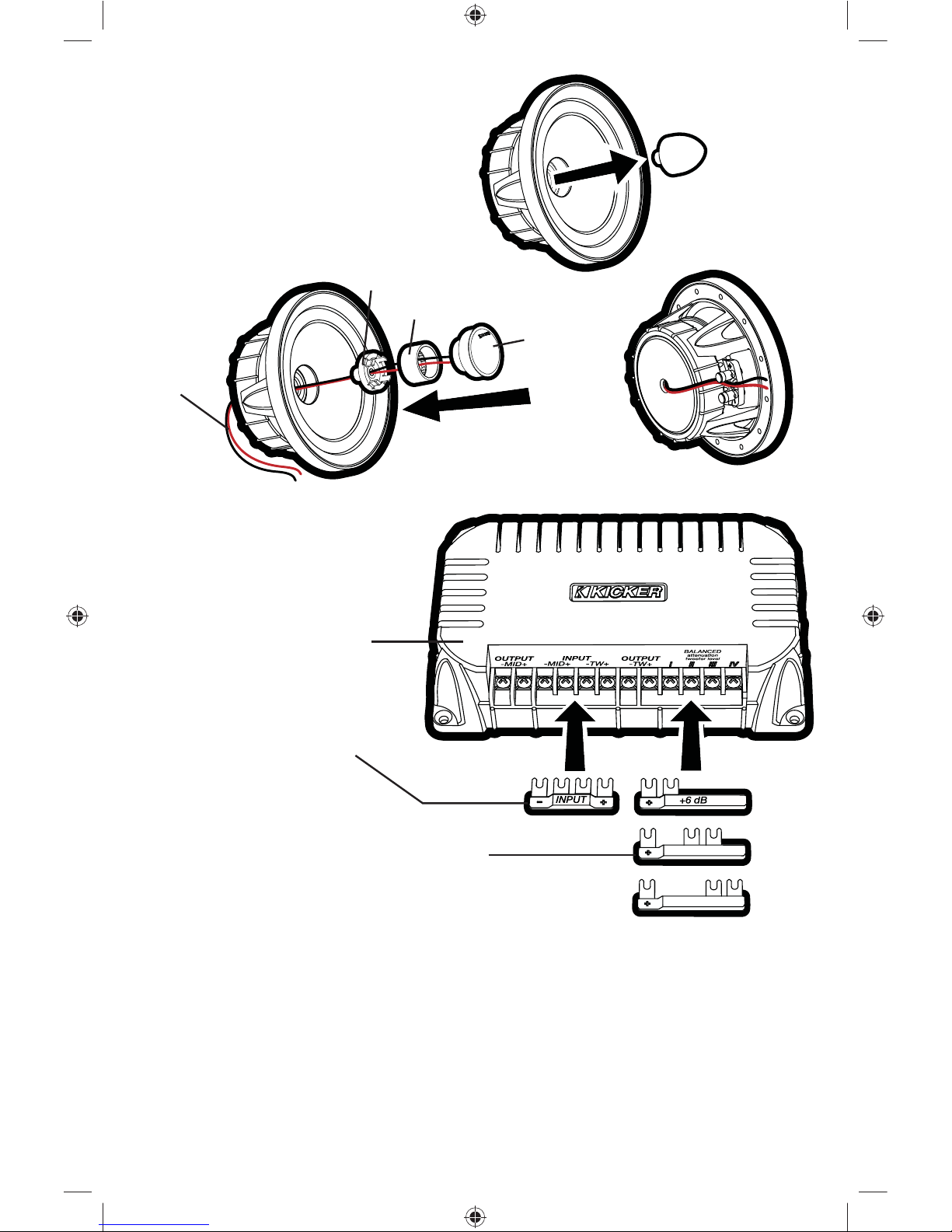
Crossover High Pass Filter 24dB/octave @ 2.8kHz 24dB/octave @ 2.8kHz
Crossover Low Pass Filter 12dB/octave @ 2.8kHz 12dB/octave @ 2.8kHz
High Frequency Output Level 0dB, +3dB, +6dB 0dB, +3dB, +6dB
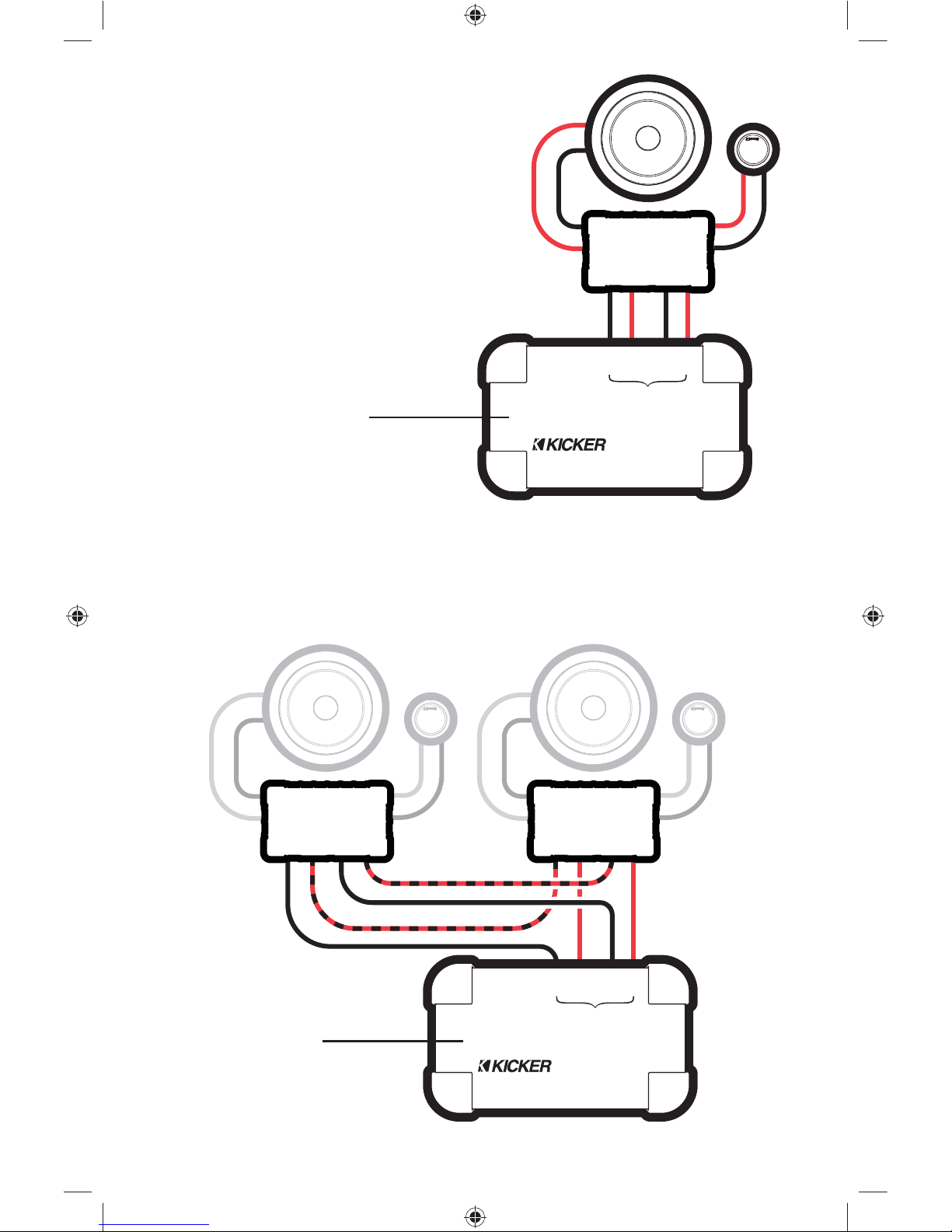
Pro Tip: Looking for the next step in audio performance from your QS components? Upgrade to a
KICKER IX or ZX 4-channel amplifier for each QS component system you have installed to take full
advantage of the QS’s bi-amping capabilities. With a dedicated amplifier channel for each tweeter and
each midrange driver, you’ll have a more efficient system that will deliver a clearer soundstage and
an increasingly dramatic dynamic response. In other words, your music will be more expansive and
captivating.
MODEL: QS65.2 / QS60.2
2009 QS Multilingual h01.indd 22009 QS Multilingual h01.indd 2 11/21/2008 10:54:27 AM11/21/2008 10:54:27 AM

3
CONFIGURATION
Before mounting and wiring the QS component system, determine which configuration you will use for the
speakers and crossover.
QS Speaker
Configurations ADVANTAGES CONSIDERATIONS
Coaxial great for space-limited applications
or when separate tweeter mounting
is not possible
high frequencies may not be as
prominent | tweeter output may
need to be increased at crossover
Separates optimal sound quality and improved
sonic imaging (with proper tweeter
mounting)
trickier install | vehicle must have a
good tweeter mounting location
QS Crossover
Configurations ADVANTAGES CONSIDERATIONS
Conventional 2-way easy install | ideal when available
amplifier channels are limited
audio fidelity not quite as high as
bi-amplified configuration
Bi-amplified optimal sound quality; more efficient
usage of amplifer power
requires at least 4 amplifier
channels | slightly trickier install
SPEAKER CONFIGURATION
The QS component system comes packaged in a separates configuration.
To use a coaxial configuration, see Fig. 1 and follow these steps:
Unscrew and remove the aluminum phase plug from the center of the woofer.1.
Screw the coaxial mounting adapter into the woofer in place of the phase plug.2.
Screw the tweeter into the tweeter post.3.
Thread the tweeter’s lead wires through the center of the woofer.4.
Snap the tweeter post onto the coaxial mounting adapter.5.
Rotate the tweeter clockwise for the most appealing position.6.
Secure the tweeter’s lead wires using the clip on the underside of the woofer.7.
Coaxial Configuration Separates Configuration
tweeter
tweeter
phase plug
2009 QS Multilingual h01.indd 32009 QS Multilingual h01.indd 3 11/21/2008 10:54:27 AM11/21/2008 10:54:27 AM

4QSCOMPONENTSYSTEM
CROSSOVER CONFIGURATION
The KICKER QS crossover can be configured as a conventional 2-way crossover by installing the
included INPUT jumper into the - MID + -TW + input terminals as shown in Fig. 2. In this configuration,
the amplified signal from your source unit or amplifier should be wired to the + and - terminals indicated on
the INPUT jumper.
The QS crossover can also be configured for bi-amp wiring by removing (or simply not installing) the
INPUT jumper. To use the bi-amp configuration, you must connect two amplified signals to each
crossover (you will need at least four amplifier channels). Install one of the included tweeter output-
level jumpers (0 dB, +3 dB, or +6 dB) to adjust the tweeter output level. Installing jumpers with higher
numbers will result in more volume from the tweeter.
Step 1
Steps 2–6 Step 7
tweeter
tweeter post
coaxial mounting adapter
tweeter lead
wires
QS crossover
0 dB
+3 dB
INPUT jumper.
Install only for 2-way configurations;
do not install if bi-amping.
tweeter output-level jumpers.
One of these jumpers MUST be installed. Higher
numbers mean more volume from the tweeter.
Fig. 2
Fig. 1
Configuring the QS for
Coaxial Operation
2009 QS Multilingual h01.indd 42009 QS Multilingual h01.indd 4 11/21/2008 10:54:27 AM11/21/2008 10:54:27 AM

5
WIRING
We recommend using 16 gauge (or larger) wire. The QS components are rated at 4 ohms and work
with any source unit or amplifier designed to operate at a 4 ohm load. Make sure your source unit or
amplifier is rated for 4 ohm operation.
Crossover in 2-way configuration | One component set per channel
At least two amplifier channels are needed for stereo operation (only one channel is shown)•
- IN +
OUT
-MID+
OUT
-TW+
-OUT+
+-
+-
+
-
+
-
+
-
+
-
- OUT +
- IN +
OUT
-MID+
OUT
-TW+- IN +
OUT
-MID+
OUT
-TW+
Crossover in 2-way configuration | Two component sets per channel
Requires two complete QS systems (four woofers, four tweeters, four crossovers)•
At least two amplifier channels are needed for stereo operation (only one channel is shown)•
Crossovers wired in series•
tweeter
crossover
woofer
source unit / amplifier
2009 QS Multilingual h01.indd 52009 QS Multilingual h01.indd 5 11/21/2008 10:54:28 AM11/21/2008 10:54:28 AM

6QSCOMPONENTSYSTEM
+
-
+
-
+
-
+
-
IN
-MID+
IN
-TW+
-OUT
+MID
OUT +
TW -
IN
-MID+
-MID+
CH2
LEFT OUTPUT
IN
-TW+
-TW+
CH1
-OUT
+MID
OUT +
TW -
Crossover in bi-amp configuration | One channel per component set
Requires two complete QS systems (four woofers, four tweeters, four crossovers)•
At least four amplifier channels are needed for stereo operation (only two channels are shown)•
Crossovers wired in series•
+
-
+
-
IN
-MID+
IN
-TW+
-OUT
+MID
OUT +
TW -
-MID+
CH2
LEFT OUTPUT
-TW+
CH1
Crossover in bi-amp configuration
Two channels per component set
At least four amplifier channels are needed•
for stereo operation (only two channels are
shown)
amplifier / source unit
(must have at least four channels)
amplifier / source unit
(must have at least four channels)
2009 QS Multilingual h01.indd 62009 QS Multilingual h01.indd 6 11/21/2008 10:54:29 AM11/21/2008 10:54:29 AM

7
WOOFER MOUNTING
The KICKER QS components are designed for free-air applications and do not require a sealed enclosure
for optimum performance. It is important to isolate the sound coming from the front of the speaker from
the sound radiating from the back of the speaker. This is most easily accomplished by mounting the
speakers in a vehicle’s factory locations or in a location with a semi-isolated rear chamber (like the rear
deck of a car behind the rear seats).
If you are replacing factory speakers in their original locations, you may have to enlarge the speaker
cut-outs and pre-drill new screw holes using a 7/64” (2.5mm) bit. Custom mounting locations will require
more preparation and work. Make sure that the speaker will not interfere with trunk and door opening and
closing mechanisms and that the enclosed screws will not puncture the fuel tank, puncture wiring, or
interfere with any other mechanical parts on the underside of the mounting surface. Cycle the windows all
the way down and up.
If the speaker cut-out locations require you to cut metal, avoid structural metal and braces. If the door
body and panel cannot support the weight of the speaker, an optional reinforcing ring (thin piece of wood
or Medium Density Fiberboard) may be fastened or adhered to the door body. Mount the speaker to the
vehicle as outlined in Fig. 3.
door body
door panel
speaker cut-out
QS woofer
speaker grille
screws
reinforcing ring (optional)
Fig. 3
2009 QS Multilingual h01.indd 72009 QS Multilingual h01.indd 7 11/21/2008 10:54:30 AM11/21/2008 10:54:30 AM

8QSCOMPONENTSYSTEM
Fig. 4
Flush Mounting the Tweeter
TWEETER MOUNTING
The tweeter can be mounted one of three ways: flush, angled, and coaxial mounting. For flush mounting
applications, see Fig. 4. Choose a flat location on the panel with space behind the panel to allow room
for the mounting nut, motor structure, and tweeter post. After checking the clearances, cut a 1-13/16”
(46mm) diameter mounting hole in the panel. Position the mounting nut behind the panel. Feed the
wire through the optional flush ring, the hole in the panel, and the mounting nut. Mount the tweeter by
screwing the mounting nut onto the tweeter.
For angled mounting applications choose a flat location on the panel with space behind the panel to
allow room for the mounting nut, motor structure, tweeter post, and back angle ring. After checking the
clearances, cut a 1-13/16” (46mm) diameter mounting hole in the panel. Place the front angle ring in front
of the panel. Then place the wire and tweeter through the front angle ring and into the panel. Next, place
the wire through the back angle ring, place the back angle ring over the rear of the tweeter, and line-up
the narrow part of the front angle ring for the preferred angle of operation. Place the wire through the
mounting nut and loosely tighten the mounting nut around the tweeter. Rotate all the parts in unison until
the tweeter is angled in the desired direction. Secure the assembly by tightening the mounting nut. See
Fig. 5.
mounting nut
Trim the mounting nut legs at the score
lines to accommodate thicker panels.
mounting nut
back angle ring
Fig. 5
Angle Mounting the Tweeter
front angle ring
rounded surface
inset surface
panel
panel
flush ring
tweeter
tweeter
2009 QS Multilingual h01.indd 82009 QS Multilingual h01.indd 8 11/21/2008 10:54:30 AM11/21/2008 10:54:30 AM

9
CROSSOVER MOUNTING
Mount the crossover in a location that is easy to access for wiring and tweeter output level adjustment.
Make sure that the crossover will not be exposed to water. The bottom of the car door is not a good
location. If you must mount the crossover in the car door, exercise caution as water can accumulate in the
bottom of the door. Keep the crossover high in the door and shielded from water.
door jamb
QS crossover.
(mounted inside
door panel)
rubber
grommets
from amplifier or
source unit
woofer mounting hole
tweeter mounting hole
to woofer
terminals
to tweeter
lead wires
If factory speaker wiring is not available in your desired location, it may be necessary to run speaker wire
through the door jamb. The speaker wire should be kept away from sharp edges and avoid the possibility
of getting pinched by the door. An existing grommet in the door jamb is the ideal place to run the speaker
wire. If the factory hole and grommet do not exist or are inaccessible, you must drill a hole to run the
speaker wire through the door jamb. Be careful not to drill into other wiring or existing door mechanisms.
Any time a wire is run through a hole, it is necessary to insert a rubber or plastic grommet to protect the
wire from damage.
2009 QS Multilingual h01.indd 92009 QS Multilingual h01.indd 9 11/21/2008 10:54:30 AM11/21/2008 10:54:30 AM

10 QSCOMPONENTSYSTEM
GRILLE MOUNTING
2009 QS Multilingual h01.indd 102009 QS Multilingual h01.indd 10 11/21/2008 10:54:31 AM11/21/2008 10:54:31 AM

11
ACOUSTICS LIMITED WARRANTY
KICKER warrants this product to be free from defects in material and workmanship under normal use for a period of
THREE (3) MONTHS from date of original purchase with receipt. When purchased from an Authorized KICKER Dealer it
is warranted for ONE (1) YEAR from date of original purchase with receipt. In all cases you must have the original receipt.
Should service be necessary under this warranty for any reason due to manufacturing defect or
malfunction during the warranty period, KICKER will repair or replace (at its discretion) the defective merchandise
with equivalent merchandise at no charge. Warranty replacements may have cosmetic scratches and blemishes.
Discontinued products may be replaced with more current equivalent products. This warranty is valid only for the original
purchaser and is not extended to owners of the product subsequent to the original purchaser. Any applicable implied
warranties are limited in duration to a period of the express warranty as provided herein beginning with the date of the
original purchase at retail, and no warranties, whether express or implied, shall apply to this product thereafter. Some
states do not allow limitations on implied warranties; therefore, these exclusions may not apply to you. This warranty
gives you specific legal rights; however you may have other rights that vary from state to state.
WHAT TO DO IF YOU NEED WARRANTY OR SERVICE:
Defective merchandise should be returned to your local Authorized Stillwater Designs (KICKER) Dealer for warranty
service. Assistance in locating an Authorized Dealer can be found at www.kicker.com or by contacting Stillwater Designs
directly. You can confirm that a dealer is authorized by asking to see a current authorized dealer window decal.
If it becomes necessary for you to return defective merchandise directly to Stillwater Designs (KICKER), call the KICKER
Customer Service Department at (405) 624-8510 for a Return Merchandise Authorization (RMA) number. Package only
the defective items in a package that will prevent shipping damage, and return to:
Stillwater Designs, 3100 North Husband St, Stillwater, OK 74075
The RMA number must be clearly marked on the outside of the package. Please return only defective components. The
return of functioning items increases your return freight charges. Non-defective items will be returned freightcollect to you.
For example, if a subwoofer is defective, only return the defective subwoofer, not the entire enclosure. Include a copy
of the original receipt with the purchase date clearly visible, and a “proof-of-purchase” statement listing the Customer’s
name, Dealer’s name and invoice number, and product purchased. Warranty expiration on items without proof-of-
purchase will be determined from the type of sale and manufacturing date code. Freight must be prepaid; items sent
freight-collect, or COD, will be refused.
WHAT IS NOT COVERED?
This warranty is valid only if the product is used for the purpose for which it was designed. It does not cover:
o Damage due to improper installation
o Subsequent damage to other components
o Damage caused by exposure to moisture, excessive heat, chemical cleaners, and/or UV radiation
o Damage through negligence, misuse, accident or abuse. Repeated returns for the same damage may be
considered abuse
o Any cost or expense related to the removal or reinstallation of product
o Speakers damaged due to amplifier clipping or distortion
o Items previously repaired or modified by any unauthorized repair facility
o Return shipping on non-defective items
o Products with tampered or missing barcode labels
o Products returned without a Return Merchandise Authorization (RMA) number
o Freight Damage
o The cost of shipping product to KICKER
o Service performed by anyone other than KICKER
HOW LONG WILL IT TAKE?
KICKER strives to maintain a goal of 48-hour service for all acoustics (subwoofers, midrange drivers, tweeters,
crossovers, etc) returns. Delays may be incurred if lack of replacement inventory or parts is encountered. Failure to
follow these steps may void your warranty. Any questions can be directed to the KICKER Customer Service Department
at (405) 624-8510. Contact your International KICKER dealer or distributor concerning specific procedures for your
country’s warranty policies.
P.O. Box 459 • Stillwater, Oklahoma 74076 • USA • (405) 624–8510
Note: All specifications and performance figures are subject to change. Please visit www.kicker.com for the
most current information. To get the best performance from your new KICKER speakers, we recommend using
genuine KICKER accessories and wiring. Please allow two weeks of break-in time for the speakers to reach optimum
performance.
20081107+G-09QS
stillwaterdesigns
2009 QS Multilingual h01.indd 112009 QS Multilingual h01.indd 11 11/21/2008 10:54:31 AM11/21/2008 10:54:31 AM

12 SISTEMADE COMPONENTESQS
Manual del propietario del SISTEMA DE
COMPONENTES QS
COMPONENTES QS
Los sistemas de componentes de la serie QS de KICKER ofrecen una fidelidad de audio inigualable para
aplicaciones para vehículos. Ya sea para configurar el último sistema de sonido envolvente con altavoces
múltiples y subwoofer o simplemente para mejorar la versión de parlantes aburridos y sin vida de fábrica,
los sistemas de componentes QS brindan el sonido de gama completa más placentero del mercado en
la actualidad!
RENDIMIENTO
Distribuidor autorizado de KICKER:
Fecha de compra
Número de modelo del altavoz:
Modelo: QS60.2 QS65.2
Tamaño del woofer 6” (160 mm) 6,5” (165 mm)
Tamaño del tweeter 1-3/16” (30 mm) 1-3/16” (30 mm)
Material del domo Tetoron®Tetoron®
Impedancia, (Resistencia CC) 4Ω, (3.5Ω)4Ω, (3.5Ω)
Procesamiento de potencia máxima,
(valor eficaz, root mean square, RMS)
180 W, (90 W) 200 W, (100 W)
Sensibilidad a 1 W/1 m 86 dB 87 dB
Gama eficaz de frecuencias 50 Hz–22 kHz 40 Hz–22 kHz
Diámetro del orificio de montaje del woofer
5-1/16” (129 mm) 5-7/16” (138 mm)
Profundidad de montaje del woofer ≤2,5” (63,5 mm) ≤2,5” (63,5 mm)
Diámetro del orificio del tweeter 1-13/16” (46 mm) 1-13/16” (46 mm)
Profundidad de montaje al ras del tweeter
1-1/8” (29 mm) 1-1/8” (29 mm)
Filtro de paso alto crossover 24 dB/octava a 2,8 kHz 24 dB/octava a 2,8 kHz
Filtro de paso bajo crossover 12 dB/octava a 2,8 kHz 12 dB/octava a 2,8 kHz
Nivel de salida de alta frecuencia 0 dB, +3 dB, + 6 dB 0 dB, +3 dB, + 6 dB
Consejo profesional: ¿Busca mejorar el rendimiento de audio de sus componentes QS? Actualice
cada sistema de componentes QS que tenga instalado en un amplificador de 4 canales KICKER IX o ZX
para aprovechar al máximo la capacidad de biamplificación de QS. Con un canal amplificador dedicado
para cada tweeter y cada excitador de alcance medio, tendrá un sistema más eficaz que producirá un
campo acústico más claro y una respuesta dinámica cada vez más espectacular. En otras palabras, su
música será más expansiva y cautivadora.
MODELO: QS65.2 / QS60.2
2009 QS Multilingual h01.indd 122009 QS Multilingual h01.indd 12 11/21/2008 10:54:32 AM11/21/2008 10:54:32 AM

13
Configuración coaxial Configuración por separado
tweeter
tweeter
corrector
de fase
CONFIGURACIÓN
Antes de montar y realizar el cableado del sistema de componentes QS, determine qué configuración
utilizará para los altavoces y el crossover.
Configuraciones de
los altavoces QS
VENTAJAS CONSIDERACIONES
Coaxial
Excelente para aplicaciones con
espacio limitado o cuando no es posible
el montaje del tweeter por separado
Es posible que las frecuencias altas
no sean tan prominentes | Es posible
que se necesite aumentar la salida
del tweeter en el crossover
Por separado Óptima calidad de sonido y mejor
imagen acústica (con el montaje
adecuado del tweeter)
Instalación más difícil | El vehículo
debe tener una buena ubicación
de montaje del tweeter
Configuraciones
del crossover QS VENTAJAS CONSIDERACIONES
Convencional de
2 vías
Fácil de instalar/Ideal cuando los canales
para amplificadores son limitados
Fidelidad de audio no tan buena como
en la configuración biamplificada
Biamplificada Óptima calidad de sonido;
uso más eficiente de la potencia
del amplificador
Requiere al menos 4 canales para
amplificadores | Instalación un
poco más difícil
CONFIGURACIÓN DE LOS ALTAVOCES
El sistema de componentes QS viene empaquetado en una configuración por separado.
Para utilizar una configuración coaxial, vea la Fig. 1 y siga los pasos a continuación:
Desatornille y retire el corrector de fase de aluminio del centro del woofer.1.
Atornille el adaptador de montaje coaxial en el woofer en el lugar del corrector de fase.2.
Atornille el tweeter a la base del tweeter.3.
Pase los cables conductores del tweeter por el centro del woofer.4.
Enganche el tweeter en la base de montaje coaxial.5.
Rote el tweeter para lograr la posición más llamativa.6.
Asegure los cables de alimentación del tweeter con la pinza en la parte inferior del woofer.7.
2009 QS Multilingual h01.indd 132009 QS Multilingual h01.indd 13 11/21/2008 10:54:32 AM11/21/2008 10:54:32 AM

14 SISTEMADE COMPONENTESQS
0 dB
+3 dB
CONFIGURACIÓN DEL CROSSOVER
El crossover QS de KICKER se puede configurar como un crossover convencional de 2 vías si se instala el
puente INPUT (entrada) en las terminales de entrada - MID + - TW + como se muestra en la Fig. 2.
En esta configuración, la señal amplificada de su unidad fuente o amplificador se deben conectar a las
terminales + y - que se indican en el puente INPUT (entrada).
El crossover QS también se puede configurar para un cableado con dos amplificadores si se saca
(o simplemente no se instala) el puente INPUT (entrada). Para utilizar la configuración de dos
amplificadores, debe conectar dos señales amplificadas a cada crossover (necesitará al menos cuatro
canales para amplificadores). Instale uno de los puentes de nivel de salida del tweeter (0 dB, +3 dB
o +6 dB) incluidos para ajustar el nivel de salida del tweeter. Si se instalan los puentes con números más
altos, el tweeter producirá más volumen.
Paso 1
Pasos 2 a 6 Paso 7
tweeter
base del tweeter
adaptador de montaje coaxial
cables de
alimentación
del tweeter
crossover QS
puente INPUT (entrada)
Instalar sólo para configuraciones
de 2 vías; No instalar si es
biamplificada.
puentes de nivel de salida del tweeter.
Se DEBE instalar uno de estos puentes. Si se usan
números más altos, el tweeter produce más volumen.
Fig. 2
Fig. 1
Configuración de QS para
el funcionamiento coaxial
2009 QS Multilingual h01.indd 142009 QS Multilingual h01.indd 14 11/21/2008 10:54:32 AM11/21/2008 10:54:32 AM

15
- IN +
OUT
-MID+
OUT
-TW+
-OUT+
+-
+-
+
-
+
-
+
-
+
-
- OUT +
- IN +
OUT
-MID+
OUT
-TW+- IN +
OUT
-MID+
OUT
-TW+
CABLEADO
Se recomienda utilizar un cable calibre 16 (o más). Los componentes QS están clasificados para 4 ohms y
funcionan con cualquier unidad fuente o amplificador diseñado para operar a una carga de 4 ohms.
Asegúrese de que la unidad fuente o el amplificador estén clasificados para funcionar con 4 ohms.
Crossover en configuración de 2 vías | Un conjunto de componentes por canal
Se necesitan al menos dos canales para amplificadores para el funcionamiento en estéreo•
(se muestra un solo canal).
Crossover en configuración de 2 vías | Dos conjuntos de componentes por canal
Requiere dos sistemas QS completos (cuatro woofer, cuatro tweeter y cuatro crossover).•
Se necesitan al menos dos canales para amplificadores para el funcionamiento en estéreo•
(se muestra un solo canal).
Crossover conectados en serie.•
tweeter
filtre passif
woofer
unidad fuente /
amplificador
unidad fuente / amplificador
-SALIDA+
-SALIDA+
2009 QS Multilingual h01.indd 152009 QS Multilingual h01.indd 15 11/21/2008 10:54:33 AM11/21/2008 10:54:33 AM

16 SISTEMADE COMPONENTESQS
+
-
+
-
+
-
+
-
IN
-MID+
IN
-TW+
-OUT
+MID
OUT +
TW -
IN
-MID+
-MID+
CH2
LEFT OUTPUT
IN
-TW+
-TW+
CH1
-OUT
+MID
OUT +
TW -
+
-
+
-
IN
-MID+
IN
-TW+
-OUT
+MID
OUT +
TW -
-MID+
CH2
LEFT OUTPUT
-TW+
CH1
Crossover en configuración biamplificada | Un canal por conjunto de componentes
Requiere dos sistemas QS completos (cuatro woofer, cuatro tweeter y cuatro crossover).•
Se necesitan al menos cuatro canales para amplificadores para el funcionamiento en estéreo•
(solo se muestran dos canales).
Crossover conectados en serie.•
Crossover en configuración
biamplificada Dos canales por
conjunto de componentes
Se necesitan al menos cuatro canales para•
amplificadores para el funcionamiento en
estéreo (solo se muestran dos canales).
Amplificador / unidad fuente
(debe tener al menos cuatro canales)
amplificador/unidad fuente
(debe tener al menos cuatro canales)
SALIDA
SALIDA
2009 QS Multilingual h01.indd 162009 QS Multilingual h01.indd 16 11/21/2008 10:54:34 AM11/21/2008 10:54:34 AM

17
MONTAJE DEL WOOFER
Los altavoces componentes Kicker QS han sido diseñados específicamente para montarlos en
aplicaciones al aire libre. Estos altavoces no necesitan caja sellada para dar un rendimiento óptimo.
Es importante separar el sonido radiado por delante del sonido radiado por detrás del excitador. Esta
separación se logra normalmente instalando el excitador en una ubicación de altavoz preestablecida de
fábrica o provista de una cámara trasera semiaislada.
Si va a cambiar los altavoces de fábrica sin cambiar su ubicación original, puede ser necesario agrandar
los cortes para altavoz y hacer nuevos agujeros piloto con una broca de 7/64 de plg. (2.5 mm).
Las ubicaciones de montaje personalizado requieren más preparación y trabajo. En cualquier caso,
asegúrese de que el altavoz no interfiera con los mecanismos de apertura y cierre de la puerta y de
la cajuela, y de que los tornillos incluidos no perforen el tanque de gasolina ni rompan el cableado ni
interfieran con ninguna otra pieza mecánica debajo o detrás de la superficie de montaje. Suba y baje
completamente los vidrios de las ventanas.
Si la ubicación de los cortes para altavoz exige cortar metal, evite cortar los refuerzos o el metal
estructural. Si el panel y la estructura de la puerta no soportan el peso del altavoz, se puede fijar o adherir
un anillo de refuerzo opcional (pieza delgada de madera o de Plancha de Fibra de Densidad Media
{Medium Density Fiberboard, MDF}) a la estructura de la puerta. Monte el altavoz en el vehículo como se
indica en la Figura 3.
estructura de la puerta
panel de la puerta
orificio del altavoz
woofer QS
rejilla del altavoz
tornillos
anillo de refuerzo (opcional)
Fig. 3
2009 QS Multilingual h01.indd 172009 QS Multilingual h01.indd 17 11/21/2008 10:54:35 AM11/21/2008 10:54:35 AM

18 SISTEMADE COMPONENTESQS
Fig. 4
Montaje al ras del tweeter
MONTAJE DEL TWEETER
El tweeter se puede montar de tres maneras: montaje al ras, en ángulo y coaxial. Para aplicaciones de
montaje al ras, vea la Fig. 4. Elija una ubicación plana en el panel con espacio suficiente detrás para la
tuerca de montaje, la estructura del motor y la base del tweeter. Después de controlar los espacios libres,
corte un orificio de montaje de 1-13/16” (46 mm) de diámetro en el panel. Coloque la tuerca de montaje
detrás del panel. Introduzca el cable a través del anillo al ras opcional, el orificio del panel y la tuerca de
montaje. Atornille la tuerca de montaje en el tweeter para montarlo.
Para aplicaciones de montaje en ángulo, elija una ubicación plana en el panel con espacio suficiente
detrás para la tuerca de montaje, la estructura del motor, la base del tweeter y el anillo angular trasero.
Después de controlar los espacios libres, corte un orificio de montaje de 1-13/16” (46 mm) de diámetro
en el panel. Coloque el anillo angular delantero frente al panel. Luego, coloque el cable y el tweeter a
través del anillo angular trasero y en el panel. A continuación, coloque el cable a través del anillo angular
trasero, coloque el anillo angular trasero sobre la parte trasera del tweeter y alinee la parte angosta del
anillo angular delantero para lograr el ángulo de funcionamiento deseado. Coloque el cable a través de la
tuerca de montaje y apriete suavemente la tuerca de montaje alrededor del tweeter. Gire todas las piezas
juntas hasta que el ángulo del tweeter quede en la dirección que desee. Para asegurar el conjunto,
apriete la tuerca de montaje. Vea la Fig. 5.
tuerca de montaje
Recorte los tramos de la tuerca de
montaje por las líneas de las ranuras
para adaptarlo a paneles más gruesos.
tuerca de montaje
anillo angular trasero
Fig. 5
Montaje en ángulo del tweeter
anillo angular delantero
superficie redondeada
superficie de inserción
panel
panel
anillo al ras
tweeter
tweeter
2009 QS Multilingual h01.indd 182009 QS Multilingual h01.indd 18 11/21/2008 10:54:35 AM11/21/2008 10:54:35 AM

19
MONTAJE DEL CROSSOVER
Monte el crossover en una ubicación que sea de fácil acceso para realizar el cableado y ajustar el nivel
de salida del tweeter. Asegúrese de que el crossover no quede en un lugar que se pueda mojar. La
parte inferior de la puerta del automóvil no es una buena ubicación. Si tiene que montar el crossover en
la puerta del automóvil, tenga cuidado ya que se puede acumular agua en la parte inferior de la puerta.
Mantenga el crossover en un lugar alto de la puerta y protegido del agua.
batiente de
la puerta
crossover QS
(montado dentro del
panel de la puerta)
arandelas
de goma
desde el
amplificador o
unidad fuente
orificio de montaje del
woofer
orificio de montaje del tweeter
hacia las
terminales
del woofer
hacia las terminales
del tweeter
Si no hay cableado de fábrica para altavoz en el lugar deseado, puede ser necesario encaminar el cable
que se incluye a través de la jamba de la puerta. Este cable debe mantenerse alejado de los bordes
afilados para que la puerta no pueda aplastarlo por accidente. La arandela de goma que pueda haber
en la jamba de la puerta es el lugar ideal para hacer pasar los cables de altavoz. Si no hay agujero con
arandela de goma de fábrica, o el que hay es inaccesible, es necesario hacer un agujero para pasar los
cables de altavoz por la jamba de la puerta. Tenga cuidado de no dañar otros cables o mecanismos de la
puerta. Cada vez que se hace pasar un cable a través de un agujero, es necesario insertar una arandela
de plástico o de goma para proteger el cable.
2009 QS Multilingual h01.indd 192009 QS Multilingual h01.indd 19 11/21/2008 10:54:35 AM11/21/2008 10:54:35 AM

20 SISTEMADE COMPONENTESQS
MONTAJE DE LA REJILLA
2009 QS Multilingual h01.indd 202009 QS Multilingual h01.indd 20 11/21/2008 10:54:36 AM11/21/2008 10:54:36 AM
This manual suits for next models
1
Table of contents
Languages:
Other Kicker Speakers System manuals

Kicker
Kicker KMT67 User manual

Kicker
Kicker KM60 User manual

Kicker
Kicker KM620.2 User manual

Kicker
Kicker PowerBar KPB1 User manual

Kicker
Kicker KMT6 User manual

Kicker
Kicker KS5.2 User manual

Kicker
Kicker I350 User manual

Kicker
Kicker PS692 User manual

Kicker
Kicker 1350 User manual

Kicker
Kicker QS65.2 User manual