Kilews KFA-0850H User manual

AUTOMATIC SCREW FEEDER
KFA-0850H (PICK UP TYPE)
Instruction Manual
(ENGLISH)
Please read this manual thoroughly, before operating the unit and retain it for future
reference.
Patented in China, Taiwan, Japan & Korea.
Imitation of product will be caused prosecution.
Y2F152-5-003

SAFETY INSTRUCTIONS
PLEASE NOTE FOLLOWING CONDITIONS BEFORE USING KILEWS KFA-0850
◎For a normal performance, please install this machine on a flat and stable
working
table, do not slant or pad, otherwise machine function might be
affected.
◎Turn off the power switch and unplug the AC adaptor when this machine is not
being used for a period of time.
◎To avoid damage and malfunction, use the AC adaptor supplied with this
machine only.
◎Keep the surface of the rail groove clean and free from dust and oil. Failure to
keep the rail groove clean could result in damage to the machine.
◎The applied screws must be clean without grease or dust, and screw size is
within specified range as machine rail.
◎Handle screws on rails with care, do not use excess force to remove them or the
rails may be damaged.
◎When scooping chamber is turning, do not put fingers or objects other than
screws into the chamber.
◎Do not turn ON the power switch before the rails are set properly for operation.
◎In case of malfunction during operation, please turn off the power and unplug
the AC adaptor. Contact your supplier at once.
Whenever this machine requires service, please contact your supplier for
assistance, or go to our website & e-mail us your contact detail and
requirement, we will respond ASAP.

CONTENTS
CHECK BEFORE OPERATION…………………………..………………………1
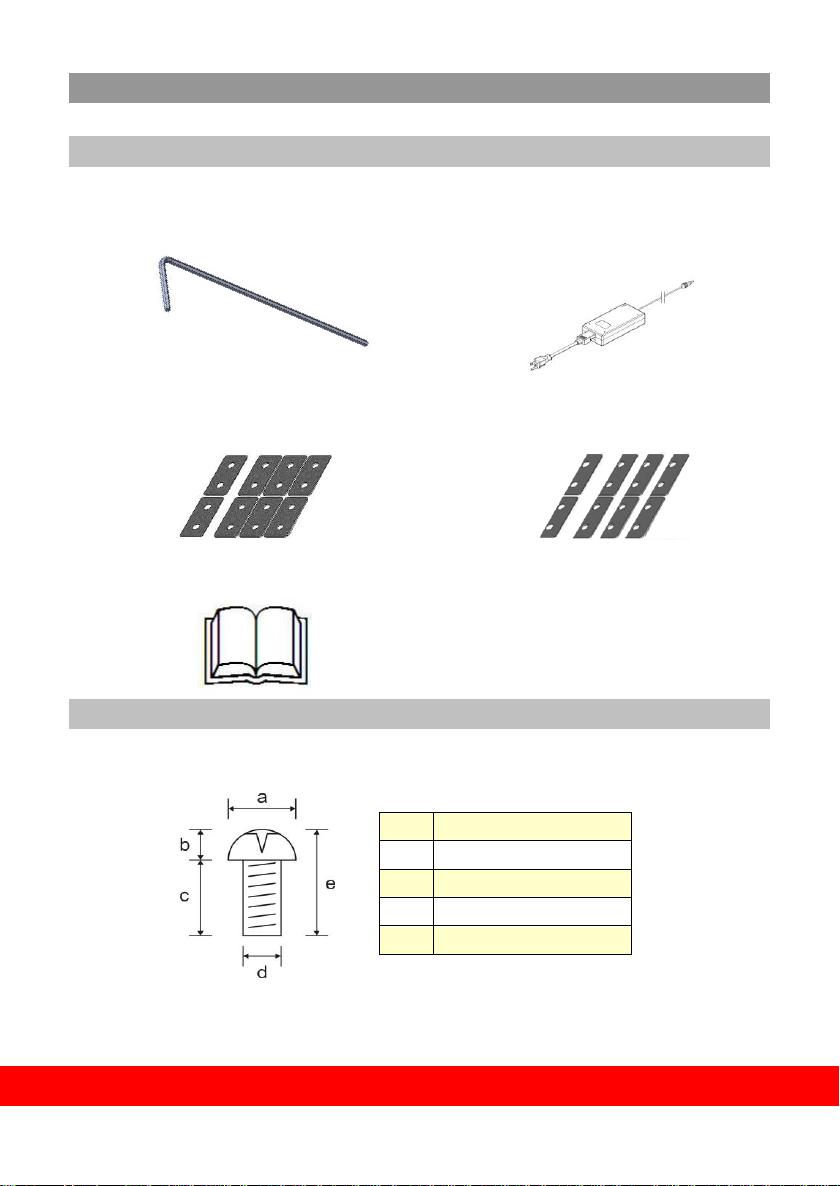
ACCESSORIES INCLUDED…………………………………………………….1
CHECK THE SCREW SIZE………………………..……………………..…1
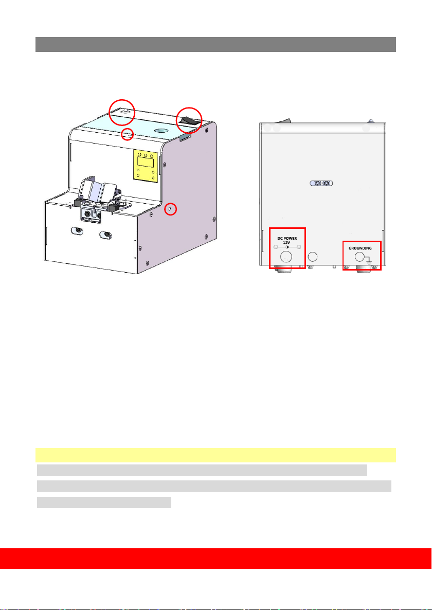
FUNCTIONS WITH ADJUSTING HOLES ON HOUSING AND PCB ……... .2
ADJUSTMENT………………………………………………………………………3
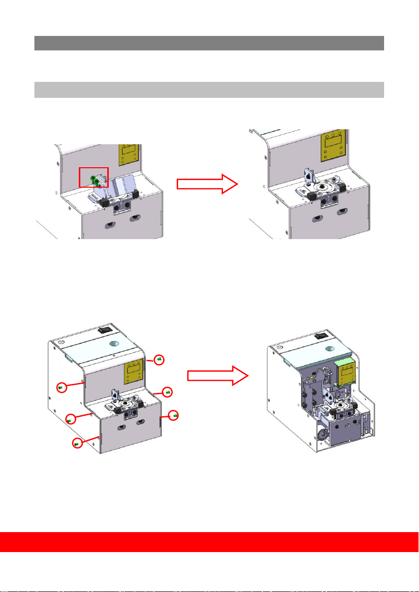
ADJUST THE RAIL ASSEMBLY…………………………………………………3
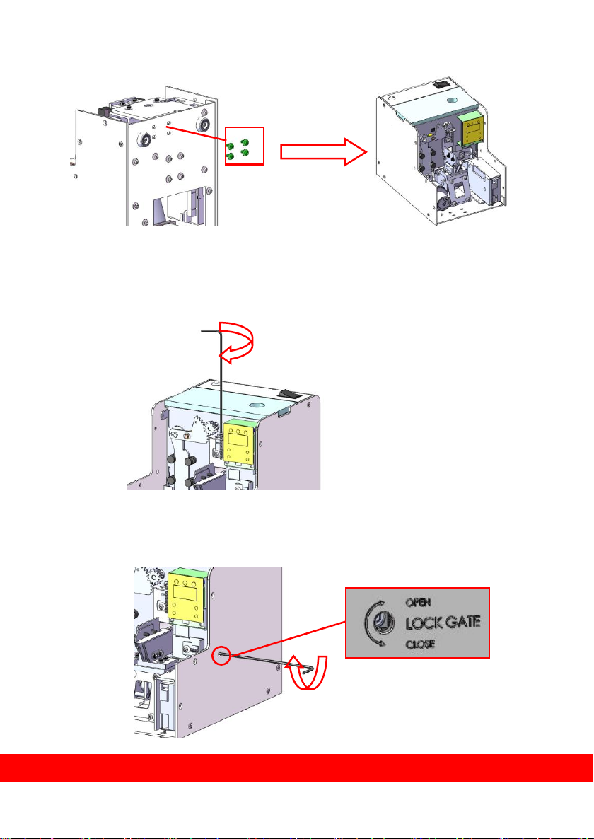
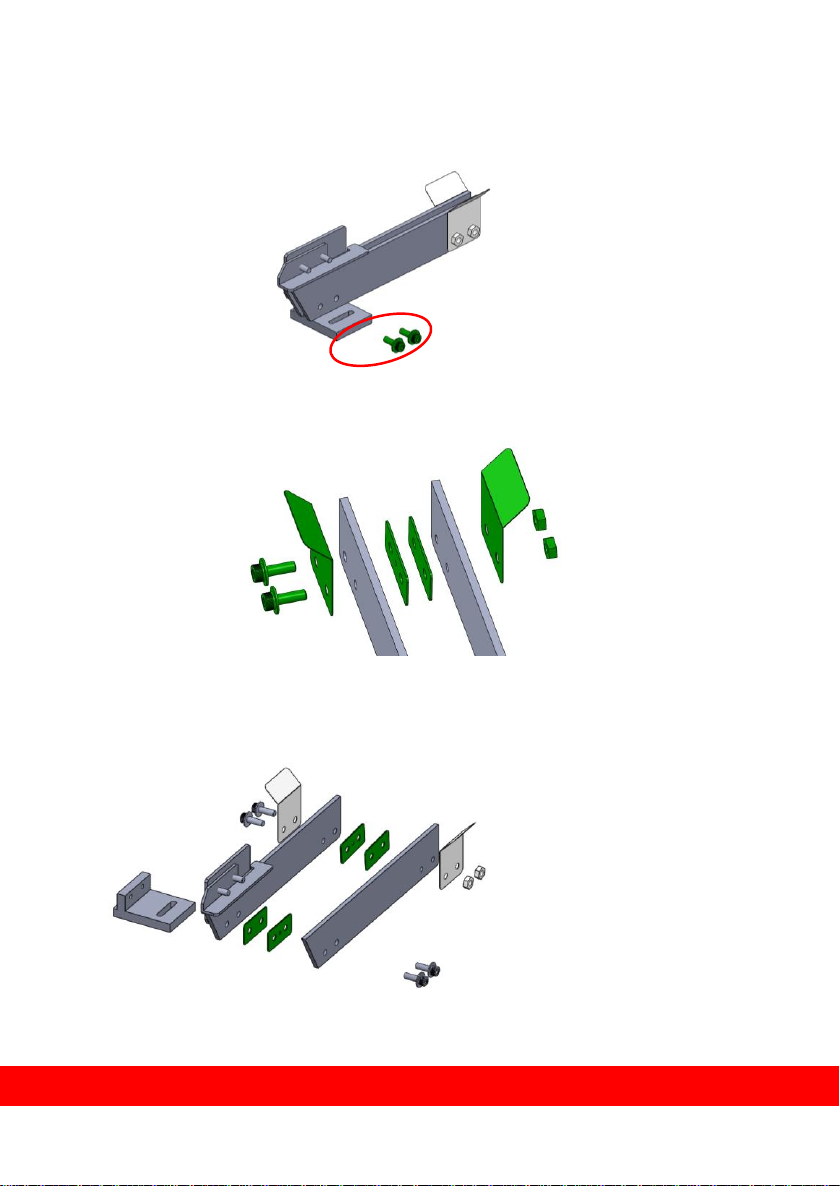
DISMANTLE THE RAIL ASSEMBLY………………………………………….3
ADJUST THE WIDTH OF RAIL ASSMEBLY…………………………………6
INSERT THE RAIL ASSEMBLY……………………………………………….8
ADJUST THE HOLDING PLATE……………………………………………….10
ADJUST THE FEEDING STRUCTURE……………………………………….11
ADJSUT THE SENSOR FUNCTION…………………………………………..13
ADJUST THE V CHASE ON ROLLER......……………………………………14
ADJUST THE BRUSH…………………………………………………………..15
OPERATION METHOD……………………………………………………………16
LOAD SCREWS INTO CHAMBER…………………………………………….16
PICKING UP SCREW…………………………………………………………...17
COUNTER INTERFACE OPERATION………………………………………18~20.
MAINTENANCE & TROUBLE SHOOTING……………………………….……21
MAINTENANCE & CLEANING…………………………………………………..22
INTERNATIONAL WARRANTY CONDITIONS………………………………...23~24

1
CHECK BEFORE OPERATION
ACCESSORIES INCLUDED
Please check if there are complete accessories included with your KFA-0820H:
CHECK THE SCREW SISE
Measure the size precisely on each part of applied screw with a caliper.
Table A
HEX Wrench 2.0*107mmL Type*1
Power Controller AC 100~240V/DC12V*1
Orbit Back-End Chip Rule
20*10*0.2mm*2pcs&0.5mm*6pcs
Orbit Front-End Chip Rule
20*10*0.2mm*2pcs&0.5mm*6pcs
Instruction Manual*1
a
Dia. of screw head
b
Height of screw head
c
Length of screw body
d
Dia. of screw bolt
e
Total length of screw

2
FUNCTION WITH ADJUSTING HOLES ON HOUSING AND PCB
A. Lock Gate Plate
B. Power S.W.
C. Indication Light
D. DC Power Hole
E. Grounding Hole
※Attention ※
a. Part F, G, H are installed and set properly by Kilews, please do not adjust by your own.
b. Part F、G、H are installed in the inside of PCB, please do not use any tools and adjust it by
your own to avoid damage the VR.
A.
B.
C.
D.
E.
.
A.

3
ADJUSTMENT
After checking the screw size, it needs to adjust all related parts according to
the screw size for the first use.
ADJUST THE RAIL ASSEMBLY
1.Remove the fixing screws of guide assembly, dismantle the guide assembly.
2. Remove the fixing screws (6pcs) of front housing, and take off the front
housing.

4
3. Dismantle the fixing screws (4pcs) of feeding structure, and take it off.
4. Facing the machine, use Hex wrench to loose the screw clockwise to open
the lock gate upward.
5. Facing the machine, use Hex wrench to loose the screw clockwise to open
the lock gate rightward.

5
6. Remove the fixing screws of rail assembly
7. Draw out the rail assembly from the machine.
※NOTE THE FOLLOWING WHEN MAKING ABOVE ADJUSTMENT※
a. Before dismantle the rail assembly, please confirm the lock gate status is
open.
The fixing
screws of
rail
assembly

6
ADJUST THE WIDTH OF RAIL ASSEMBLY
1. Remove the fixing screws on the front end of rail assembly.
2. Remove the fixing screw on the rear end of side of rail assembly, take off
the tooling plate
3. According to Table b, insert the suitable tooling plate into the rail groove
for the width required and tighten the screw
of step 1.2.

7
※COMBINATION OF THE THICKNESS FOR REFERENCE ※Table b
Dia. of Screw Bolt
(d) mm
Accessory-Tooling
Plate (Rear) mm
Dia. of Screw
Bolt (d) mm
Accessory-Tooling
Plate (Rear) mm
1.2
0.5*2+0.2*2=1.4
2.5
0.2 + 0.5 * 5 = 2.7
1.4
0.2*3+0.5 *2 = 1.6
3.0
0.2 + 0.5 * 6 = 3.2
1.7
0.2 * 2 + 0.5 * 3 = 1.9
3.5
0.2 + 0.5 * 7 = 3.7
2.0
0.2 + 0.5 * 4 = 2.2
4.0
0.2 + 0.5 * 8 = 4.2
2.3
0.5 * 5 = 2.5
5.0
0.2+ 0.5 * 10 = 5.2
4. After width adjustment of the rail assembly, take one screw into the
groove and slide it up and down to both sides. Then check whether the
movement is smoothly.
※NOTE THE FOLLOWING WHEN MAKING ABOVE ADJUSTMENT※
a. Please be sure to keep the width of rail from the beginning to the end
uniformly.
b. When adjusting the width of front rail assembly, the screw of step 1 must
be fastened tightly.

8
INSTALL THE RAIL ASSEMBLY
1. Insert the adjusted rail assembly into the machine. Then fasten the fixing
screws.
2. Install the feeding structure, and then fasten screws.

9
3. Adjust up and right gate to make distance between rail and gate around
0.2~0.5mm.
4. Loosen rail fixing screw, adjust distance between the front of rail and
disc around 0.2~0.5mm, fasten the screw.
※NOTE
a. Rail installation must keep 0.2~0.5mm gap with disc, must not be touched.
b. When rail cannot install successfully, please check.
c. Must keep 0.2~0.5mm gap between up、right gate and rail.
0.2~0.5mm
0.2~0.5mm

10
Force-down plate adjustment
1. Loosen fixing screw on force-down plate.
2. Use accessory tooling plate adjust height of force-down plate and then
fasten screw in step1.
3. Put some screws into the groove and slide it up, to check whether the
movement is smooth.
※NOTE
a. When adjust force-down plate, the screw in step 1 must fasten tightly to
avoid loosing.

11
Distribution Mechanism adjustment
1. Loosen fixing screw from front of distribution mechanism.
2. Align disc gap with central of rail by adjust front of distribution mechanism
by left and right, fasten the loosen screw in step 1.
3. Loosen two hexagon screws.

12
4. Adjust from part by up and down to make disc and rail flush, and then
fasten loosen screw in step 3.
※NOTE ※
a. Align disc gap with central of rail, and upper plane cannot higher than
upper plane of front rail.
b. Disc plane cannot higher than rail plane.
Flush

13
Adjust Sensor Function
1. Loosen the fixing screw of sensor fixing plate
2. Make sure to cover half of the hole, and then fasten the screw of step 1.
※NOTICE ※
a. Make sure to cove half of the hole, and do adjustment to ensure the sensor function no
problem.

14
Adjust V Chase on Scooping Chamber Back
The V Chase is locate on top of the rail, and fastened to the back of Roller Assembly. The
purpose is to catch fallen screws from the Rollers, and guide screws back to the rail.
1. Using the Allen wrench to loosen the Hex Socket Head Cap Screws behind the main body
2. Adjust V Chase to face to the center of the rail. Distance between Chase and rail should be
0.8~1.0mm
※NOTICE ※
a. Keep 0.8~1.0mm open space between V Chase and the end of the rail,and V Chase aligned
to the center of the rail.
0.8~1.0mm

15
Adjust the Brush
1. Swing the brush to stay almost horizontal, loosen screw on the side of brush bracket.
2. Place 5~8 screws into the rail groove close to the holding plate rear end and loosen 2 screws
on the side of the brush bracket. Swing the brush and adjust the height until the brush just
touch the screw heads slightly, and tighten the screws after adjustment.
3. When fix the brush position, keep suitable space form the Front Plate and Fixing Plate.
4. Brush bracket and driving rod must be parallel and fix to the
center.
※NOTICE ※
a. After adjustment of the
height of the brush, swing
the brush by hand to
make sure the movement
runs smoothly.
b. The brush length is
inconsistently, please
ensure the brush match
rail when replace it.

16
Method of Operation
Load Screws Into the Chamber
Turn off the power first, and open the Top Cover Box. Ensure the screws are loaded without
foreign materials, pour in screws until they come up to 1~2mm below the top on both sides of
the rails.
Can contain screws between 200~220cc. All objects other than applied screw are deemed as
foreign material which should be removed first; or it will affect the performance of this machi

17
PICK UP SCREWS
Make sure the bit type onyour electric screwdriver matches the head of the screw, and the
bit is magnetized before use.(Bit that not magnetized willnot stick with the screw andscrew
willfall offafter picking up).
Hold the screwdriver and put the driver bit above the Bit Guideand push it straight down to
"+" on top of thescrewas figure below.
※CAUTION FOR THE ABOVE OPERATING ※
a. Do not push the driver bit with too much force when picking up the screw, or it will adamge
the Rail Assembly.
b. Do not deliberately apply force on the Rail Assembly or it will damage the machine.
Table of contents
Other Kilews Industrial Equipment manuals
Popular Industrial Equipment manuals by other brands

Blichmann
Blichmann Tower of Power LTE Assembly operation maintenance

IRO
IRO IWF 2231-B operating instructions

HES
HES HS0753 user manual

schmersal
schmersal AZM201Z-I2-SK-T-1P2PW-DU Operation and assembly instructions

PR electronics
PR electronics 4512 product manual

Virutex
Virutex EB140PLC Premilling quick start guide

PCB Piezotronics
PCB Piezotronics M205C Installation and operating manual

Cleveland
Cleveland NT-100 Operation manual

LNS
LNS Alpha 552 instruction manual

Electrocorp
Electrocorp Clean Breeze III Operation and maintenance manual

READY
READY EPSON VT6L Startup guide

Aerotech
Aerotech LaserTurn 5-ASR Hardware manual