STM RFA Series Instruction Manual
RFA RFA
RFA-RFW-AI
A T E X
A T E X
INCLUDED
Riduttori
AI
RFW
AI
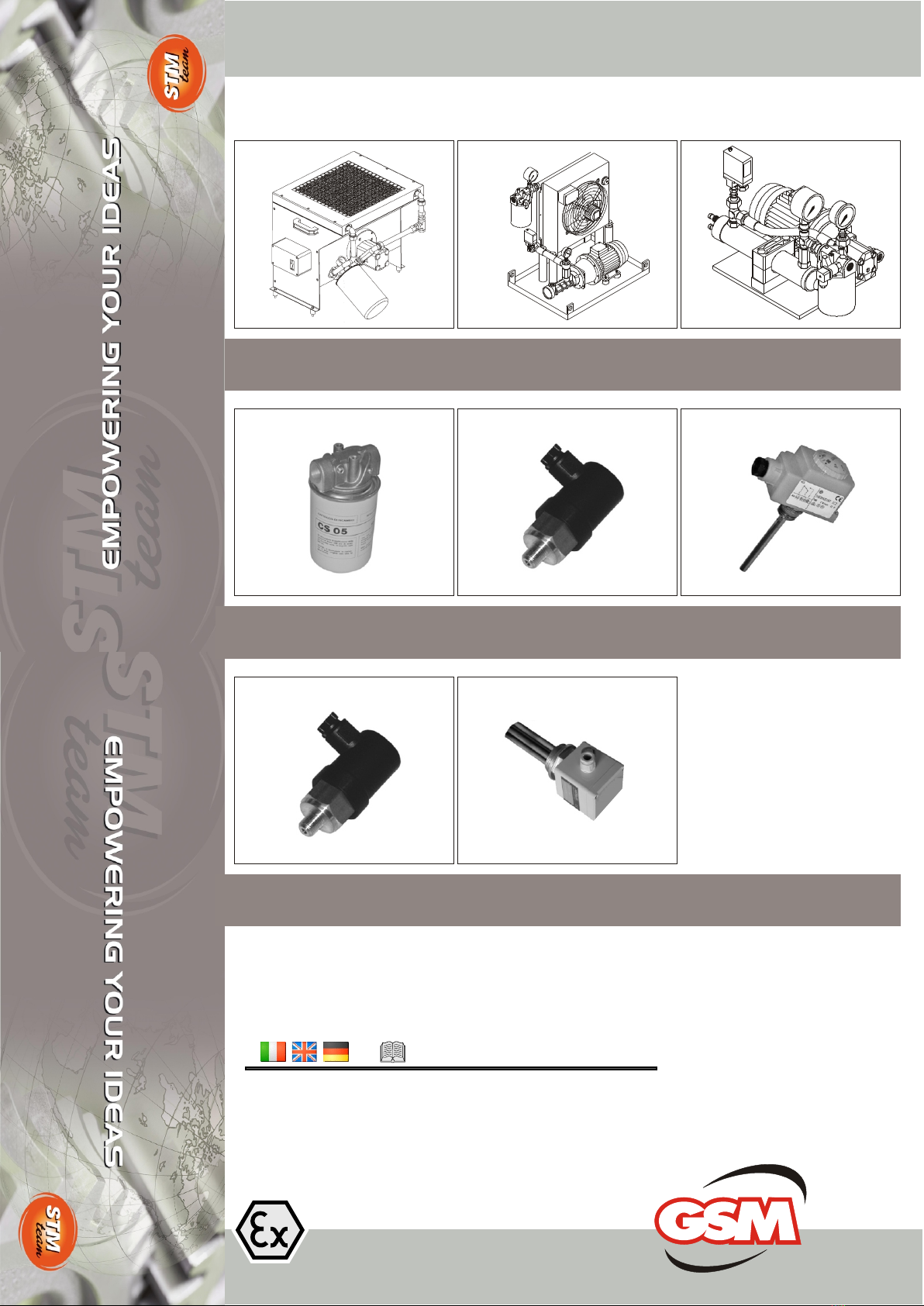
Filtro olio
Oil filter
Ölfilter
Termostato
Temp. switch
Thermostat
Riscaldatore
Heater
Heizelement
AI AI
AI
GSM_mod. MT 02 I GB DGSM_mod. MT 02 I GB D
Sonda Bimetallica
Bimetallici Probe
Bimetal-Sonde
Pressostato
Pressure switch
Druckschalter
Installation and MaintenanceInstallation and Maintenance
Installation and MaintenanceInstallation and Maintenance

1
GSM_mod.MT02 IGBD 0.3
RX
Series
Riduttori
Industrial
2
GSM_mod.MT02 IGBD 0.3
RX
Series
Riduttori
Industrial
0. GENERAL INFORMATION 0. ALLGEMEINE INFORMATIONEN0. INFORMAZIONI GENERALI
0.1 SCOPO
0.2 LIMITI DELLA GARANZIA
0.3 AVVERTENZE GENERALITA’
SULL’USO
0.1 PURPOSE
0.2 LIMITS OF THE WARRANTY
0.3 WARNINGS-GENERAL
NOTES ON CORRECT USE
0.1 EINSATZZWECK
0.2GARANTIE-
EINGRENZUNGEN
0.3 ALLGEMEINE
3
3
3
Pagina Page Seite
CHAPTER PARAGRAPHPARAGRAFO
3
1. SAFETY RULES 1. SICHERHEITSNORMEN1. NORME DI SICUREZZA 2
2. IDENTIFICATION 2. KENNZEICHNUNG2.IDENTIFICAZIONE 4
2.1 TARGHETTA
2.2 SIGLA DEL PRODOTTO
2.1 IDENTIFICATION PLATE
2.2 PRODUCT NAME
3. SCOPE OF THE SUPPLY 3. LIEFERZUSTAND3. STATO DI FORNITURA
3.1 PREMESSA
3.2 GRUPPO RFW
3.3 GRUPPO RFA
5
5
7
3.1 VORWORT
3.2 RFW-AGGREGAT
3.3 RFA-AGGREGAT
3.1 FOREWORD
3.2 RFW UNIT
3.3 RFA UNIT
5
4. LIFTING AND HANDLING 4. HEBEN UND TRANSPORT
4.SOLLEVAMENTO TRASPORTO 11
5. STOCKING 5. EINLAGERUNG5. STOCCAGGIO 11
6. TYPES OF COMMISSIONING
PROCEDURES
6. INBETRIEBSETZUNGSARTEN6. TIPOLOGIE MESSA SERVIZIO 11
6.1 CLASSIFICAZIONE
6.2 DESCRIZIONE
TIPOLOGOLIE
11
12
6.1 CLASSIFICATION
6.2 DESCRIPTION OF
COMMISS. PROCEDURES
6.1 KLASSIFIKATION
6.2 BESCHREIBUNG DER
INBETRIEBSETZUNGSARTEN
7. INSTALLATION 7. INSTALLATION7. INSTALLAZIONE 14
7.1 LUOGO FUNZIONAMENTO
7.2 LUOGO CHIUSO E/O
POLVEROSO
7.3 LUOGO APERTO
7.4 ILLUMINAZIONE
7.5 FISSAGGIO
7.6 COLLEGAMENTO IMPIANTO
IDRAULICO
7.7 POSIZIONE TAPPI
14
14
14
14
14
14
15
7.1 INSTALLATION SITE
7.2 ENCLOSED AND/OR DUSTY
ROOM
7.3 OUTDOOR INSTALLATION
7.4 LIGHTING
7.5 FASTENING THE UNIT
7.6 HYDRAULIC SYSTEM
CONNECTION
7.7 PLUGS POSITION
7.1 INSTALLATIONSORT
7.2 GESCHLOSSENER
UND/ODER STAUBIGER
INSTALLATIONSORT
7.3 INSTALLATION IM FREIEN
7.4BELEUCHTUNG
7.5BEFESTIGUNG DES
AGGREGATS
7.6
8. COMMISSIONING 8. INBETRIEBSETZUNG8. MESSA IN SERVIZIO
8.1 GRUPPI RFW
8.1.1 Schema idraulico
8.1.2 Schema elettrico
8.1.3 Messa in Servizio
8.2 GRUPPI RFA
8.2.1 Schema idraulico
8.2.2 Schema elettrico
8.2.3 Messa in Servizio
Schema A
8.2.4 Messa in Servizio
Schema B
8.2..5 Controlli
16
17
17
17
18
18
19
21
22
22
16
9. MAINTENANCE 9. INSTANDHALTUNG9. MANUTENZIONE 23
4
4
9.1 GRUPPO RFW
9.2 GRUPPO RFA 23
24
9.1RFW-AGGREGAT
9.2 RFA-AGGREGAT
9.1 RFW UNIT
9.2 RFA UNIT
10. SIZE 10. BEMASSUNG10. DIMENSIONAMENTO 25
11. INSTRUMENTS DATA SHEET 11. DATENBLATT DER
INSTRUMENTE
11. DATASHEET STRUMENTI 26
8.1 RFW UNIT
8.1.1 Hydraulic diagram
8.1.2 Wiring diagram
8.1.3 Commissioning
8.2 RFA UNIT
8.2.1 Hydraulic diagram
8.2.2 Wiring diagram
8.2.3 Commissioning
Diagram A
8.2.4 Commissioning
Diagram B
8.2..5 Inspection
2.1 TYPENSCHILD
2.2PRODUKTKENNZEICHNUNG
8.1 AGGREGAT RFW
8.1.1 Hydraulikschema
8.1.2 Schaltplan
8.1.3 Inbetriebsetzung
8.2 RFA-AGGREGAT
8.2.1 Hydraulikschema
8.2.2 Schaltplan
8.2.3 Inbetriebsetzung -
schema A
8.2.4 Inbetriebsetzung -
schema B
8.2.5 Kontrolle

3
GSM_mod.MT02 IGBD 0.3
RX
Series
Riduttori
Industrial
0.1 EINSATZZWECK
Die Kühlung durch Wärmeaustauscher lässt
sich in zwei Haupttypologien unterteilen:
1 - Wasser-Öl-Wärmeaustauscher RFW
2 - Luft-Öl-Wärmeaustauscher RFA.
Jede Kategorie enthält mehrere Baugrößen mit
unterschiedlichen Austauschleistungen. Jedes
Kühlaggregat wird getrennt vom Getriebe geliefert.
Die Verbindungsleitungen zwischen Getriebe und
Anlage werden von der GSM vorgesehen. Dieses
Handbuch enthält alle Informationen für eine
korrekte Lagerung, den Einsatz und die
Instandhaltung. Der Einhalt dieser Hinweise ist
im Sinne der Gewährleistung eines korrekten
Betriebs eine wesentliche Ausgangsbedingung.
Es wird empfohlen, den Inhalt dieses Handbuch
zur Kenntnis zu nehmen und eine Kopie davon
in der Nähe der Kühlaggregate aufzubewahren.
Die Hauptinformationen mit allgemeinem
Charakter sind nicht nur für die serienmäßigen
Kegelrad- und Parallelwellengetriebe sondern
auch für die Spezialgetriebe gültig.
0.2 GARANTIEEINGRENZUNGEN
Die Garantie beschränkt sich ausschließlich auf
den Austausch der defekten Komponente, wenn
nach einer Überprüfung eine effektive Verantwor-
tung unsererseits festgestellt wird.Die auf das Pro-
dukt gegebene Garantie verfällt in dem Moment, in
dem Handhabungen, egal an welchem Teil oder
welcher Komponente der Anlage, festgestellt wer-
den.Von der Garantie ausgeschlossen sind dar-
über hinaus Reparaturen, die in Folge von
Schäden erforderlich sind, die durch Nachlässig-
keit in der Instandhaltung oder unangemessene
Applikationen verursacht wurden.
Alle für den Transport, Kontrolle und Ausbauarbei-
ten entstehenden Kosten für den Eingriff einer
unser Techniker gehen immer und vollständig
zu Lasten des Kunden.
0.3 ALLGEMEINE EINSATZHINWEISE
Die Kühlaggregate GSM S.p.A. Serie RFW/RFA
wurden ausschließlich für die Kühlung von Hydrau-
liköl entwickelt und können daher nicht zur Kühlung
anderer Flüssigkeiten verwendet werden.Vor Be-
ginn irgendwelcher Instandhaltungseingriffe MUSS
DIE SPANNUNGSVERSORGUNG UNTER-
BROCHEN WERDEN, da sich im Innenbereich für
den Bediener gefährliche Teile in Bewegung befin-
den.
Sich darüber hinaus an folgende Anweisungen
halten:
- Eingriffe an der Einheit dürfen nur dem be-
fugten Personal erlaubt werden.
- NIE EINE SICH IM STÖRUNGSZUSTAND
BEFINDLICHE EINHEIT EINSCHALTEN
- Vor Einsatz der Einheit muss man sich darüber
vergewissern, dass jegliche, die Sicherheit
gefährdende Bedingung ein angemessener Weise
beseitigt wurde.
- Sicherstellen, dass alle Schutzvorrichtungen
sich an ihrem Platz befinden und dass die Sicher-
heitsvorrichtungen vorhanden und wirksam sind.
- Dafür sorgen, dass sich im Bedienerbereich kei-
ne Fremdkörper befinden.
Jegliche Instandhaltungseingriffe müssen an einer
von den Energieversorgungsnetzen (Strom, Druc-
kluft, Hydraulik oder anderweitige) getrennten Ma-
schine vorgenommen werden.
- Sollte die Möglichkeit bestehen, von herau-
sgeschleuderten oder herunterfallenden Festkör-
pern oder ähnlichem getroffen werden zu können,
müssen ggf. eine Brille mit seitlichem Schutz, ein
Helm oder Handschuhe getragen werden.
- Bei Umgang mit heißem Material kann sich im
Hinblick auf ein Verhindern von Handverbrennun-
gen das Anlegen von Schutzhandschuhen oder
anderen persönlichen Schutzkleidungsstücken als
erforderlich erweisen.
- Auch wenn die Einheit sich nicht als besonders
laut erweist, kann sich das Anlegen eines Ohren-
schutzes gegen den im Umfeld der Maschine vor-
liegenden Schalldruck als erforderlich erweisen.
0.1 SCOPO
Il raffreddamento con scambiatore di calore può
essere suddiviso in due tipologie principali:
1 - Scambiatore acqua-olio RFW
2 - Scambiatore aria olio RFA.
Ogni categoria è divisa in più grandezze, con
potenze di scambio diversificate
Ogni gruppo di raffreddamento è fornito
separatamente al riduttore; i tubi di collegamento
tra riduttore ed impianto non sono a carico GSM.
Questo manuale contiene tutte le informazioni
per il corretto stoccaggio, uso e manutenzione
ed il rispetto di queste costituisce condizione
necessaria per la garanzia di un corretto
funzionamento; è consigliabile prendere
coscienza dei contenuti di questo manuale e
conservarne una copia in prossimità dei gruppi di
raffreddamento. Le informazioni principali di
carattere generale sono valide oltre che per i
riduttori ortogonali e paralleli di serie anche per
gli speciali.
0.2 LIMITI DELLA GARANZIA
La garanzia si limita esclusivamente alla
sostituzione del componente difettoso, qualora si
determina, dopo averlo visionato, un’effettiva
nostra responsabilità.
La garanzia sul prodotto in ogni modo non ha più
valore nel momento in cui si dovessero
riscontrare delle manomissioni a qualsiasi parte
o componente l’impianto.
Si escludono inoltre dalla garanzia le riparazioni
conseguenti a danni causati da trascuratezza di
manutenzione o da applicazioni inadeguate.
Tutte le spese di trasporto, sopralluogo,
smontaggio dovute, per l’intervento di un nostro
tecnico s’intendono in ogni caso a totale carico
del cliente.
0.3 AVVERTENZE GENERALITA’ SULL’USO
I gruppi di raffreddamento GSM S.p.A. serie
RFW/RFA sono stati progettati esclusivamente
per il raffreddamento d’olio idraulico, e non
possono essere assolutamente utilizzati per
raffreddare altri liquidi.
Prima di procedere a qualunque manutenzione
SI RACCOMANDA DI TOGLIERE TENSIONE
perché all’interno ci sono parti in movimento
pericolosi per l’operatore.
Seguire inoltre le seguenti disposizioni:
-Consentire al solo personale autorizzato
d’intervenire sull’unità.
- NON AVVIARE L’UNITA’ IN AVARIA
- Prima di usare l’unità accertarsi che qualsiasi
condizione pericolosa per la sicurezza sia stata
opportunamente eliminata.
-Accertarsi che tutte le protezioni siano al loro
posto ed i dispositivi di sicurezza siano presenti
ed efficienti.
-Fare in modo che nella zona dell’operatore
non siano presenti oggetti estranei.
Qualunque operazione di manutenzione deve
avvenire con la macchina isolata dalle reti di
distribuzione dell’energia (elettrica, pneumatica,
idraulica od altro).
- Quando sussiste la possibilità d’essere colpiti
dalle proiezioni o dalla caduta di parti solide o
simili, usare gli occhiali con paraocchi laterali,
elmetti o guanti se necessari
- Quando si opera con materiale caldo può
essere richiesto l’uso di guanti od altri mezzi di
protezione individuale, per evitare scottature da
contatto manuale
-Anche se l’unità non è di per sé rumorosa, può
essere richiesto l’uso di protezioni contro il
rumore a causa del livello di pressione sonora
dell’ambiente in cui la macchina è installata.
0.1 PURPOSE
Heat exchanger cooling systems can be of two
types:
1 - Water-oil exchanger RFW
2 - Air-oil exchanger RFA.
Each category is available in many sizes, with
different exchange power. Any cooling unit is
supplied separate from gearbox; tubes
connecting gearbox and system are not at
GSM’s charge. This manual gives all instructions
about stocking, use and maintenance; follow
these rules to ensure correct operation. It is
recommended to thoroughly read this manual
and keep one copy next to the cooling units.
General information apply not only to the
standard parallel shaft and helical bevel
gearboxes but also to the special versions.
0.2 LIMITS OF THE WARRANTY
Warranty only covers replacement of faulty
component if, after inspection, fault proves to be
our responsibility. Product warranty becomes
null and void whenever any system part or
component has been tampered with. Repairs for
damage due to maintenance lack or unsuitable
application are further excluded.
All the expenses for transport, on-the-spot
inspection and disassembly consequent to the
intervention of one of our technicians are anyway
completely at customer’s charge.
0.3 WARNINGS - GENERAL NOTES ON THE
CORRECT USE OF THE SYSTEM
Cooling units by GSM S.p.A. of the RFW/RFA
series are exclusively designed for cooling
hydraulic oil and can not be used for cooling
other fluids. Before proceeding to any
maintenance operation IT IS RECOMMENDED
TO CUT OFF POWER SUPPLY because inside
the system are moving parts dangerous for the
operator.
Please stick to these provisions:
- Only allow authorised personnel to work on
the machine.
- DO NOT START THE UNIT IF FAULTY
- Before starting the unit, ensure that any
dangerous condition has been suitably
eliminated.
- Ensure that all protections are in place and
that safety devices are available and in efficient
conditions.
- Ensure that there are no foreign objects in the
operator’s area.
Cut off any machine (power, air, water or other)
supply before performing any maintenance
operation.
- If there is the risk of being hit by solid particles
(or else) falling or being projected, use goggles
with side shields, helmets or gloves, if
necessary.
- When working with hot material, it could be
necessary to wear gloves or any other safety
gear to avoid scalds.
- Though the unit is not noisy in itself, it could be
necessary to wear noise-proof protections due to
the noise level of the room where machine is
installed.
0. GENERAL INFORMATION 0. INFORMAZIONI GENERALI0. INFORMAZIONI GENERALI
4
GSM_mod.MT02 IGBD 0.3
RX
Series
Riduttori
Industrial
1. SAFETY RULES 1. SICHERHEITSNORMEN1. NORME DI SICUREZZA
I gruppi di raffreddamento vengono progettati,
costruiti e commercializzati avvalendosi di tutte
le conoscenze tecnologiche e scientifiche
attualmente a disposizione. Nell’ottica di un
naturale sviluppo delle conoscenze il costruttore
si riserva il diritto di modificare componenti al fine
di migliorarne efficienza e sicurezza. Non
dovranno essere apportate modifiche da parte
dell’utilizzatore che ne diminuiscano l’affidabilità
variando le condizioni applicative e funzionali di
contratto.
Igruppi di raffreddamento non devono essere
posti in servizio prima che la macchina in cui
saranno incorporati sia stata dichiarata conforme
alle disposizioni della Direttiva Macchine
98/37/CEE e successivi aggiornamenti e alla
Direttiva sulla compatibilità elettromagnetica
89/336/CEE e successivi aggiornamenti.
Il costruttore della macchina deve inglobare le
informazioni contenute nel presente manuale
con quelle relative alla propria macchina. Prima
di effettuare interventi occorre che il riduttore sia
fermo e che siano presi tutti i provvedimenti
necessari affinché non si abbiano accidentali
avviamenti.
Occorre prevedere una protezione delle parti
rotanti onde prevenire contatti accidentali.
In presenza di variazioni anomale di temperatura
e/o rumorosità, non motivate da variazioni
applicative, i gruppi di raffreddamento devono
essere fermati ed ispezionati per prevenire
danneggiamenti più gravi.
Tutte le normative vigenti in termini di
inquinamento ambientale, prevenzione e
sicurezza devono essere rispettate.
Die Kühlaggregate werden mit Bezugnahme auf
alle zur Verfügung stehenden technologischen
und wissenschaftlichen Kenntnisse entwickelt,
produziert und gehandelt. Unter Berücksichtigung
einer normalen Entwicklung der Kenntnisse
behält sich der Hersteller das Recht für Änderun-
gen der Komponenten vor, um den Wirkungsgrad
und die Sicherheit zu verbessern. Der Anwender
darf dagegen keinerlei Änderungen anbringen,
die zu einer Minderung der Zuverlässigkeit führen
und die dabei die Anwendungs- und Funktions-
bedingungen gemäß Vertrag variieren.
Die Kühlaggregate dürfen erst in Betrieb gesetzt
werden, wenn die Maschine, in die sie integriert
werden sollen, als mit der Maschinenrichtlinie
98/37/EWG und späteren Aktualisierungen und mit
der Richtlinie bezüglich der elektromagnetischen
Verträglichkeit 89/336/EWG und ihren späteren
Aktualisierungen als konform erklärt wurde.
Der Hersteller der Maschine muss die in
diesem Handbuch enthaltenen Informationen
durch die ergänzen, die sich auf seine Maschi-
ne beziehen. Vor Beginn von Eingriffen ist der
Stillstand des Getriebes herbeizuführen und es
müssen alle erforderlichen Maßnahmen getrof-
fen werden, damit es zu keinen erneuten
zufälligen Einschaltungen kommt.
Um einen zufälligen Kontakt zu vermeiden,
muss an den sich drehenden Teilen ein Schutz
angebracht werden. Bei Vorliegen anormaler
Temperaturänderungen und/oder Geräuschen,
die nicht auf Applikationsvariationen
rückführbar sind, müssen die Kühlaggregate
gestoppt und überprüft werden, so dass schwe-
reren Schäden vorgebeugt werden kann. Alle
gültige Richtlinien in Bezug auf Umweltschutz,
Unfallvorsorge und Sicherheit müssen einge-
halten werden.
The cooling units are designed, manufactured
and marketed exploiting all technological and
scientific know-how currently available. Within
the frame of knowledge natural development, the
manufacturer reserves the right to modify
components in order to enhance their efficiency
and safety features. The user shall not make any
changes resulting in a reduction of product
dependability or modification of intended
application and operation conditions.
The cooling units shall not be commissioned until
the machine, to which they are going to be
attached, is declared as complying with the
provisions of Machinery Directive 98/37/CEE
and its amendments as well as the Directive on
Electromagnetic Compatibility 89/336/CEE and
its amendments.
The machine manufacturer should quote the
indications given in this manual when giving
information about their machine. Before
performing any intervention, ensure that gearbox
is stopped and take all necessary steps to
ensure that no accidental start-ups occur.
It is necessary to set a protection for the rotary
parts to avoid accidents.
If temperature and/or noise level changes occur
and are not due to modifications of the
application, stop the cooling units and inspect
them to avoid severe damage. Comply with all
prevailing rules concerning environment
pollution, safety and accident prevention.
2. IDENTIFICATION 2. KENNZEICHNUNG2.IDENTIFICAZIONE
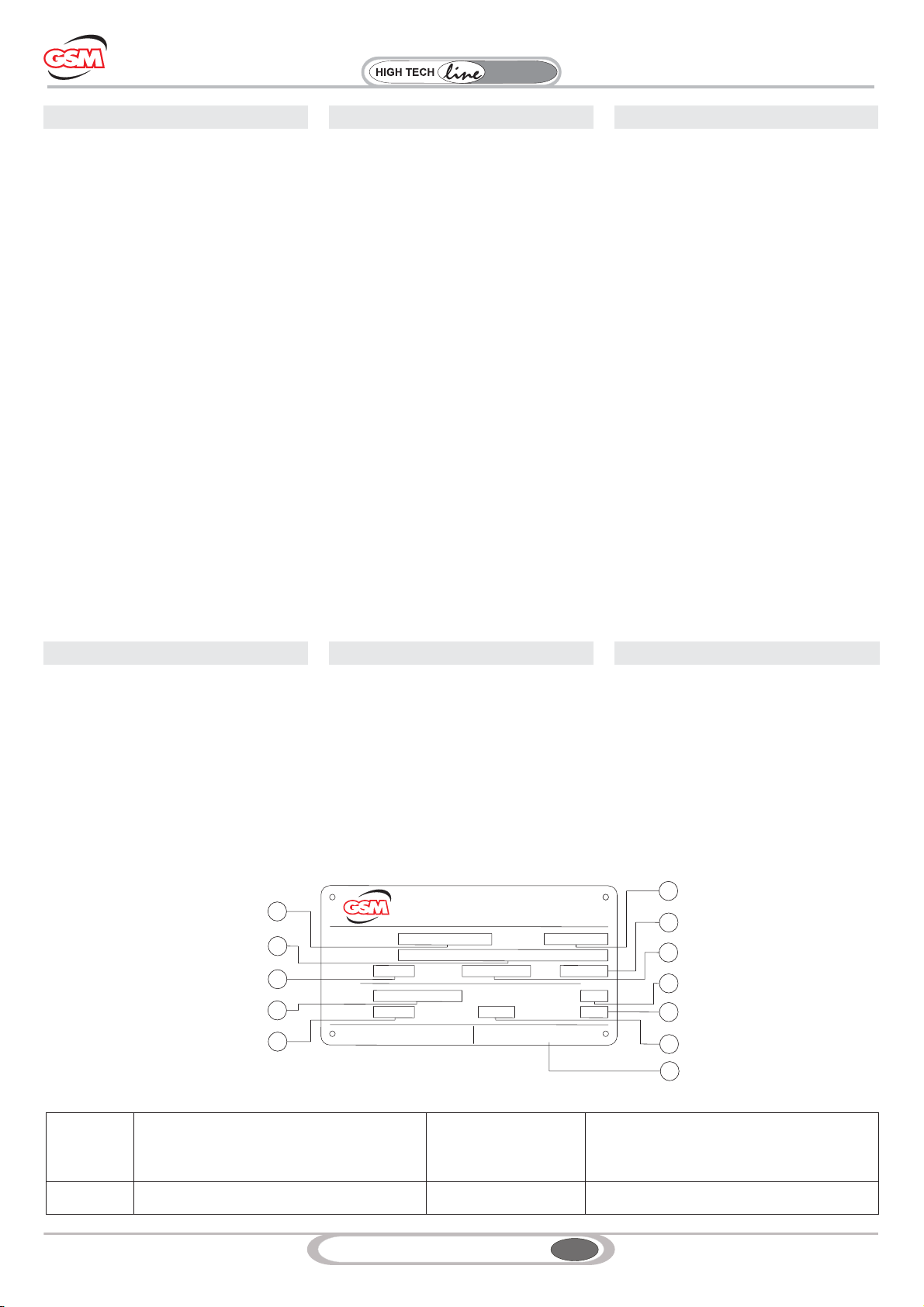
2.1 TARGHETTA
La targhetta contiene le principali informazioni
tecniche relative alle caratteristiche funzionali e
costruttive del gruppo di raffreddamento e ne
definisce i limiti applicativi contrattuali; deve
perciò essere mantenuta integra e visibile.
1: Work Order
2: sigla del gruppo
4: Data produzione
6: codice
8: potenza nominale Motopompa (kW)
12: Codice targhetta
2.2 SIGLA DEL PRODOTTO
Gruppo di Raffreddamento
Cooling Unit
Kühlaggregat
Grandezza
Size
Baugröße
Caratteristiche di Alimentazione
Power supply specs
Versorgungsdaten
[V]/[Hz]
RF W
A1-2-3-4-5 -(230-400/50)
2.1 IDENTIFICATION PLATE
The identification plate features the cooling unit
main technical details concerning its operation
and construction and sets its intended
application; it is thus very important to keep it in
good condition and in a visible place.
1:Work Order
2: unit name
4: Production date
6: code
8: Motor pump rated power (kW)
12: Code Plate
2.2 PRODUCT NAME
2.1 TYPENSCHILD
Auf dem Typenschild werden die wesentlichen
technischen Informationen bezüglich der fFun-
ktions- und Konstruktionsmerkmale des
Kühlaggregats angegeben, die die vertrags-
abhängigen Anwendungseinschränkungen defi-
nieren; es darf daher nicht beschädigt und
muss gut ersichtlich sein.
1: Werksauftrag
2: Kennzeichnung des Aggregats
4: Herstellungsdatum
6: Code
8: Richtleistung der Motorpumpe (kW)
12: Code Plate.
2.2 PRODUKTKENNZEICHNUNG
1
1
1
1
1
1
1
1
1
1
1
VIA MALAVOLTI, 48
41100 MODENA ITALY
WEB: www.stmspa.com
E-MAIL: [email protected]
W.O. NUMBER :
DESIGNATION :
RATIO :
P1 :
DATE :
kW min-1
n1 :
Riduttori
AS :
CODE :
ATEX : FT_ATEX_REV:
0123456789
10/02/02007
RFA 3
1.1 Fs :
kW
CODE :
3
7
8
2
1
4
5
9
10
11
6
7834560001
USE AND MAINTENANCE on web site
Code Plate:AAA1000266
112
5
GSM_mod.MT02 IGBD 0.3
RX
Series
Riduttori
Industrial
3. SCOPE OF THE SUPPLY 3. LIEFERZUSTAND3. STATO DI FORNITURA
3.1 PREMESSA
Esaminare la merce al momento dell’arrivo a
destinazione per verificare che non abbia subito
danni durante il trasporto. Per avarie o rotture
dovute a danni imputabili al trasporto, il
destinatario dovrà sporgere immediata
contestazione direttamente al vettore od
avvisare il nostro Ufficio Commerciale.
Il materiale danneggiato non deve essere
installato o messo in funzione per evitare rischi di
funzionamento pericoloso.
3.2 GRUPPO RFW
3.2.1 Generalità
Sempre più spesso è indispensabile raffreddare
l’olio con acqua se si ha sufficiente disponibilità
d’acqua pulita.
In alcuni casi, poi, non è possibile collegare lo
scambiatore olio-acqua direttamente allo scarico
a causa della presenza nel circuito di colpi
d’ariete, e si è costretti a realizzare un circuito
separato con una pompa autonoma di
circolazione, tubazioni, pressostato ed impianto
elettrico.
Per questi casi, ora sempre più frequenti, GSM
S.p.A. ha provveduto inserendo nella propria
produzione i gruppi autonomi di raffreddamento
serie RFW, che risolvono nel migliore dei modi il
compito di raffreddare l’olio, indipendentemente
dall’impianto idraulico primario.
L’unità è stata studiata per raffreddare l’olio e
consiste in un scambiatore a fascio tubiero che,
ponendo a contatto l'olio messo in circolazione
dalla motopompa con la serpetina dell'acqua,
asporta il calore ceduto.
Tutte le parti metalliche sono protette da
verniciatura a polvere per garantire una lunga
durata agli agenti atmosferici.
Nell’esecuzione standard l’unità è fornita con
tutti i particolari assemblati su un telaio.
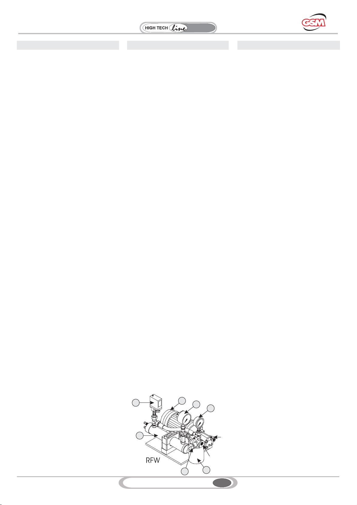
3.2.2 Stato fornitura e caratteristiche tecniche
Le unità di raffreddamento serie RFW standard
sono composte da:
1 - Uno scambiatore di calore acqua-olio;
2 - Una motopompa composta da un motore a 4
poli in forma B3/B5, alimentazione standard
trifase 230-400V 50 hz e da una pompa ad
ingranaggi o a vite;
3 - Manometro 0-16 bar montato fra pompa e
scambiatore di calore;
4 - Termometro analogico 0-120 °C, montato in
uscita dallo scambiatore;
5 - Pressostato di minima con contatti in
scambio, montato fra pompa e scambiatore di
calore;
6 - Filtro, in mandata al serbatoio, per la pulizia
dell’olio scaricato;
7 - Indicatore elettrico di intasamento
A – Aspirazione della pompa;
M – Mandata della pompa.
3.1 VORWORT
Überprüfen Sie bei Anlieferung der Ware den
entsprechenden Zustand, um so eventuelle
Transportschäden feststellen zu können. Bei
Störungen oder Brüchen, die sich auf Trans-
portschäden zurückführen lassen, muss der
Empfänger sofort und direkt an den Frachtführer
Beanstandung erstatten oder unsere Handels-
abteilung darüber in Kenntnis setzen. Das
beschädigte Material darf nicht installiert oder in
Betrieb genommen werden, so dass Gefahren
vermieden werden können.
3.2 RFW-AGGREGAT
3.2.1 Allgemeine Informationen
Immer häufiger ist es unerlässlich das Öl mit
Wasser zu kühlen, wenn ausreichend Wasser
verfügbar ist. In einigen Fällen ist ein direkter
Anschluss des Öl-Wasser-Wärmeaustauschers
an den Anschluss aufgrund von Widderstößen
im System nicht möglich und man ist dazu
gezwungen einen separaten Kreislauf mit einer
eigenständigen Umlaufpumpe, Leitungen,
Druckwächter und elektrischer Anlage zu reali-
sieren.Für diese immer häufiger auftretenden
Fälle hat die GSM S.p.A. autonome Kühlaggre-
gate der Serie RFW in ihr Programm aufgenom-
men, die die Aufgabe der Ölkühlung, von der
hydraulischen Hauptanlage unabhängig, in der
besten Art und Weise erfüllen.Diese Einheit
wurde für das Kühlen des Öls entwickelt und
stellt sich in einem Wärmeaustauscher mit
Rohrbündel dar, der die abgestrahlte Wärme
ableitet, indem er das von der Motorpumpe in
den Umlauf gebrachte Öl mit der Wasser-
rohrschlage in Kontakt bringt.
Alle Metallteile sind durch eine Pulverlack-
lackierung geschützt, die einen lang anhalteden
Schutz gegen Umweltbelastungen gewährt.
In der Standardversion wird die Einheit bereits mit
allen am Rahmen montierten Teilen geliefert.
3.2.2 Lieferzustand und technische Eigen-
schaften
Die Kühleinheiten der Serie RFW Standard
setzten sich aus folgenden Komponenten zu-
sammen:
1 - einen Wasser-Öl-Wärmeaustauscher;
2 - einer Motorpumpe bestehend aus einem
4-poligem Motor in Bauform B3/B5, Stan-
dard-Drehstromversorgung 230-400V 50 Hz
und einer Zahnrad- oder Schneckenpumpe;
3 - Manometer 0-16 bar, zwischen Pumpe und
Wärmeaustauscher montiert;
4 - analoges Thermometer 0-120 °C, am Au-
sgang des Wärmeaustauschers montiert;
5 - Mindestdruckwächter mit Wechselkontakten,
zwischen Pumpe Wärmeaustauscher montiert;
6 - Filter, im Zulauf zum Behälter, für die Reini-
gung des abgelassenen Öls
7 - elektrische Verstopfungsanzeige.
A – Ansaugung der Pumpe;
M – Zulauf der Pumpe.
3.1 FOREWORD
Upon arrival, ensure that the goods did not suffer
any transport damage. The recipient shall
immediately claim to the carrier any failure or
faults due to transport damage or report to our
Sales Department.
Any damaged material shall not be installed or
operated to avoid any risk and danger.
3.2 RFW UNIT
3.2.1 General features
If sufficient clean water is available, it is often
required to cool down oil with water. Moreover, in
some cases it is not possible to connect oil-water
exchanger directly to the drainage due to water
hammers in the circuit, and user is thus forced to
set up a separated circuit with independent
circulation pump, tubing, pressure switch and
electric system. These cases are very frequent
nowadays, this is why GSM S.p.A. has added to
its product range the independent cooling units
of the RFW series, that best carry out the task of
cooling down oil in an independent way with
respect to the main hydraulic system. This unit is
designed for cooling down oil and consists in a
tube bundle heat exchanger that sinks heat
released from oil (circulated by motor pump)
thanks to contact with water coil.
All metal parts are powder-coated to ensure long
lasting protection against weather conditions.
In the standard version, the unit features all parts
assembled to a frame.
3.2.2 Supply scope and specifications
Standard cooling units of the RFW series consist
of:
1 - A water-oil heat exchanger;
2 - A motor pump made of a 4-pole motor rated
B3/B5, standard three-phase 230-400V 50 Hz
power and a gear or screw pump;
3 - 0-16 bar Pressure gauge mounted between
pump and heat exchanger;
4 - 0-120 °C Analogue thermometer mounted at
exchanger outlet;
5 - Minimum pressure switch with switch
contacts, mounted between pump and heat
exchanger;
6 - Filter, at tank inlet, for cleaning drained oil;
7 - Electrical clogging indicator
A – Pump inlet;
M – Pump outlet.
1
52
3
4
6
7
A
M
6
GSM_mod.MT02 IGBD 0.3
RX
Series
Riduttori
Industrial
3. SCOPE OF THE SUPPLY 3. LIEFERZUSTAND3. STATO DI FORNITURA
3.2.3 Dimensionamento e Caratteristiche
Funzionali
Per la scelta del gruppo di raffreddamento si
rimanda al paragrafo 6.0 e 10.0.
CARATTERISTICHE TECNICHE
Nella Tabella sottostante riportiamo le
caratteristiche tecniche
3.2.3 Sizes and Functional Features
Please refer to chapter 6.0 and 10.0 for
indications on how to choose the suitable
cooling unit.
SPECIFICATIONS
The specifications are given in the table below
3.2.3 Bemaßung und Funktionseigenschaften
Für die Wahl des richtigen Kühlaggregats
verweisen wir auf die Paragraphen 6.0 und
10.0.
TECHNISCHE EIGENSCHAFTEN
In der nachstehenden Tabelle werden die
technischen Eigenschaften angegeben.
Grandezza
Size
Baugröße
Size
Peso
Weight
Gewicht[
[Kg]
Volume
Olio
Oil volume
Ölvolumen
[dm3]
Motopompa
Motor Pump
Motorpumpe
Scambiatore
Exchanger
Wärmeaustauscher
Campo Applicazione
Application
Einsatzbereich
[*1] [*2] [*3] [*4]
Connessione Olio
Oil connection
Ölanschluss [*7] [*8]
Raffredda
mento
Cooling
Kühlung
Lubrificazio
ne Forzata
Forced
lubrication
Zwangssch
mierung
[*5] [*6]
1 13 0,4 Ingranaggi
Gear-type
Zahnräder
0.37 6
230/400
50
G 1/2" G 3/4" G 1/2"
8-30
SI
YES
JA
SI
YES
JA
2 15 0,6 0.37 6 10-30
3 18 1,2 0.55 16 16-30
4 44 3,0
Vite
Screw-type
Schnecke
1.5 30 G 3/4" G 1" 1/4 G 1" 40-110
5 70 4,5 2.2 80 G 1" 1/4 G 1" 1/2 G 1" 80-110
6 On request 7.50 135.0 G 2" On request G 1" 90-110
7 On request 7.50 200.0 G 2" On request G 1" 180-220
8 On request 7.50 200.0 G 2" On request G 1" 270-330
Legenda/Legend/Legende
[*1] Tipo Pompa/Pump type/Pumpentyp
[*2] Potenza /Power/Leistung [kW]
[*3] Portata /Flow rate/.Durchsatz [dm3/ min]
[*4] Alimentazione /Power supply/Versorgung [V / Hz]
[*5] Aspirazione /Inlet/Ansaugung
[*6] Mandata /Outlet/Zulauf
[*7] Connessione Acqua /Water connection/Wasseranschluss
[*8] Portata Acqua /Water flow rate/Wasserdurchsatz [l / min]
1.1.4 Dimensioni 1.1.4 Maße
1.1.4 Dimensions
RFW 2 RFW 3RFW 1
350
230
350
600
430
12
12
RFW 5RFW 4
500
715
520
12
12
45
30
30
60
55
Scala 1:10
n.4 fori Ø11
15
3
X
X
520
500
860860860
710
510
320
280
350
280
450
12
12
350
320
280
450
280
12
12
RFW 7 RFW 8RFW 6
On requestOn request On request
37
2D
2D
2D
37
2D
2D
2D
38
2D
2D
2D
38
2D
2D
2D
39
2D
2D
2D

7
GSM_mod.MT02 IGBD 0.3
RX
Series
Riduttori
Industrial
3. SCOPE OF THE SUPPLY 3. LIEFERZUSTAND3. STATO DI FORNITURA
3.3 GRUPPO RFA
3.3.1 Generalità
Sempre più spesso è indispensabile raffreddare
l’olio con l’aria, poiché non si ha sufficiente
disponibilità d’acqua.
In alcuni casi poi, non è possibile collegare lo
scambiatore aria-olio direttamente allo scarico a
causa della presenza nel circuito di colpi d’ariete,
e si è costretti a realizzare un circuito separato
con una pompa autonoma di circolazione,
tubazioni, termostato ed impianto elettrico.
La GSM S.p.A. ha provveduto inserendo nella
propria produzione i gruppi autonomi di
raffreddamento serie RFA, che risolvono nel
migliore dei modi il compito di raffreddare l’olio,
indipendentemente dall’impianto idraulico
primario.
Un problema che oggi si fa sempre più pressante
è il risparmio nei consumi d’energia.
Utilizzando per il raffreddamento acqua a
perdere si spreca calore che l’olio ha ceduto
all’acqua.
Utilizzando invece l’aria emessa dai gruppi RFA
è possibile recuperare il calore ceduto dall’olio,
scaldando l’ambiente in cui essi sono installati.
Oggi, il consumo dell’acqua per usi industriali ha
costi sempre molto elevati ed in molti casi le
aziende devono munirsi d’impianti refrigeranti in
circuito chiuso dell’acqua di raffreddamento e
nella maggior parte dei casi esse sono macchine
frigorifere.
Il consumo d’energia di questi impianti è ingente
ed è pari a circa il 30% della potenza da
disperdere.
Con i gruppi autonomi serie RFA questo
consumo scende al 6%, con un considerevole
risparmio d’energia elettrica e quindi di costo
d’esercizio, senza contare il costo iniziale
notevolmente inferiore.
L’unità è stata studiata per raffreddare l’olio e
consiste in un radiatore che è attraversato dal
flusso d’aria generato da un ventilatore, il quale
lambendo le alettature in alluminio della massa
radiante asporta il calore ceduto dall’olio, che
circola nel radiatore dal basso verso l’alto grazie
alla pompa a vite di ricircolo.
Il controllo del corretto funzionamento della
macchina è regolato dai termostati che ne
ottimizzano il funzionamento nel caso
d’eventuali sbalzi di temperatura.
Tutte le parti metalliche sono protette da
verniciatura a polvere per garantire una lunga
durata agli agenti atmosferici.
Nell’esecuzione standard l’unità è fornita con
tutti i particolari assemblati su un telaio
palettizzabile
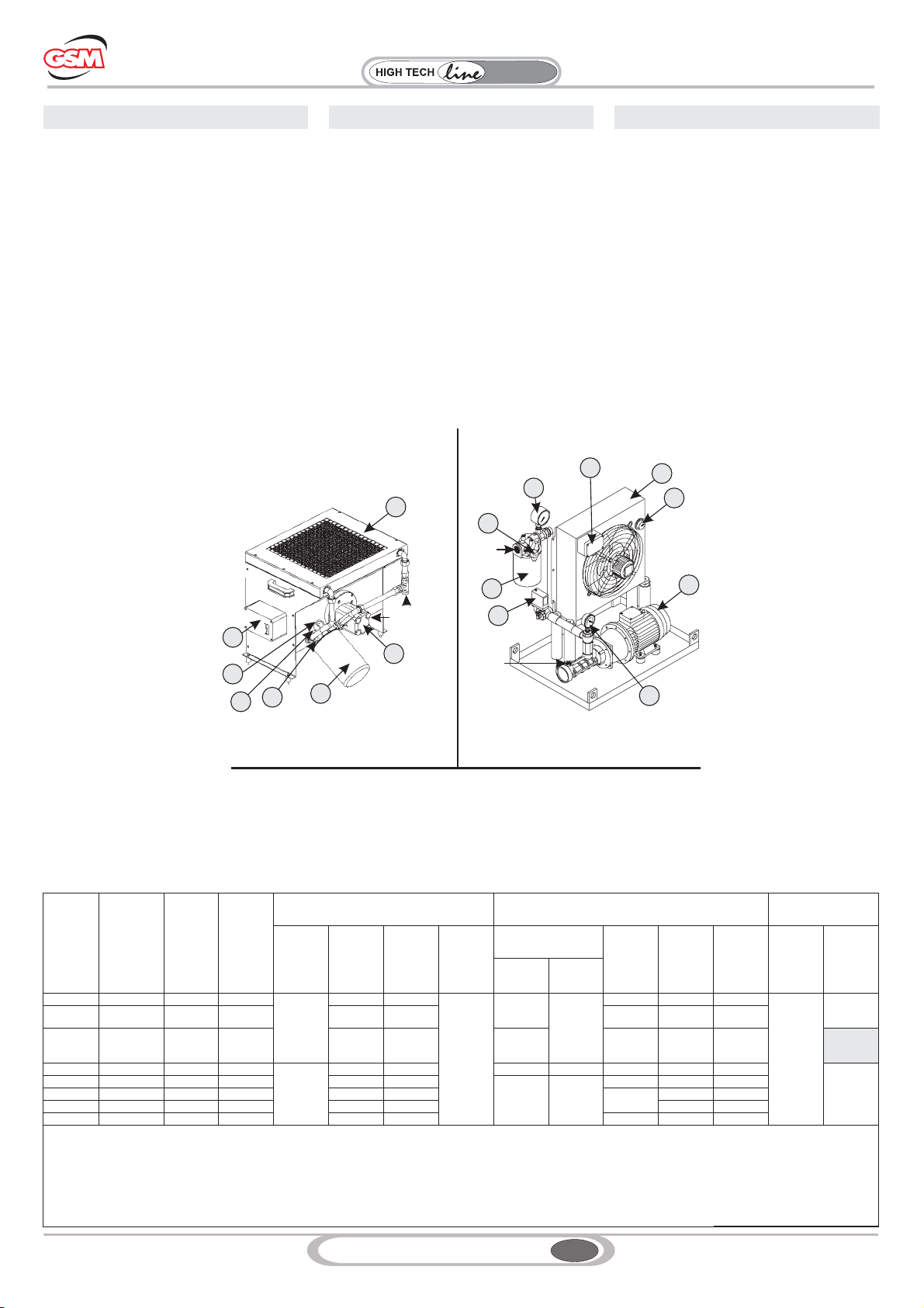
3.3.2 Stato fornitura e caratteristiche
tecniche
Le unità di raffreddamento serie RFA standard
sono composte da:
1. Uno scambiatore di calore aria-olio;
2. Una motopompa composta da un motore a 4
poli per le grandezze RFA1, RFA2, RFA3 e 2
poli per le grandezze RFA4, RFA5 in forma
B3/B5, alimentazione standard trifase
230-400V 50 hz.
Per i gruppi facenti parte dello schema A (RFA1
– RFA2 – RFA3) il motore della motopompa è il
medesimo del motoventilatore.
3. SCHEMA A: Manometro 0-12 bar con
funzione aggiuntiva di indicatore visivo di
intasamento;
SCHEMA B: Manometro 0-16 bar montato fra
pompa e scambiatore di calore ;
4. Termometro analogico 0-120 °C, montato in
uscita dallo scambiatore.
5. Pressostato di minima con contatti in
scambio, montato fra pompa e scambiatore di
calore.
6. Filtro, in mandata al serbatoio, per la pulizia
dell’olio scaricato.
3.3 RFA-AGGREGAT
3.3.1 Allgemeine
InformationenImmer häufiger ist es unerlässlich
das Öl mit Luft zu kühlen, da man nicht ausrei-
chend Wasser verfügbar hat. In einigen Fällen
ist ein direkter Anschluss des Luft-Wasser-
Wärmeaustauschers an den Anschluss auf-
grund von Widderstößen im System nicht
möglich und man ist dazu gezwungen einen se-
paraten Kreislauf mit einer eigenständigen Um-
laufpumpe, Leitungen, Thermostat und elektri-
scher Anlage zu realisieren. Die GSM S.p.A.
hat autonome Kühlaggregate der Serie RFA in
ihr Programm aufgenommen, die die Aufgabe
der Ölkühlung, von der hydraulischen Hauptan-
lage unabhängig, in der besten Art und Weise
erfüllen. Die Energieeinsparung ist heute ein
Problem, dem immer mehr Bedeutung zu-
kommt. Wird für die Kühlung nicht wiederver-
wendbares Wasser verwendet, geht die Wärme
verloren, die das Öl ans Wasser abgegeben
hat. Wird dagegen von den RFA-Aggregaten
zugeführte Luft verwendet, kann die an der Öl
abgegebene Wärme zurückgewonnen und für
die Heizung des Raums verwendet werden, in
dem sie installiert sind. Der Wasserkonsum für
den industriellen Einsatz ist heute mit immer
stärker steigenden Kosten verbunden und in
vielen Fällen müssen sich die Firmen mit
Kühlsystemen im geschlossenen Kühlwasser-
kreislauf ausrüsten, dabei handelt es sich in
den meisten Fällen um Kühlmaschinen. Der
Energieverbrauch dieser Anlagen ist beachtlich
und entspricht ungefähr 30% der verbrauchba-
ren Leistung. Mit den autonomen Aggregaten
der Serie RFA sinkt dieser Konsum auf 6% ab,
eine erhebliche Einsparung bei Strom also bei
Betriebskosten, ohne dabei die erheblich gerin-
geren Anschaffungskosten zu berücksichtigen.
Die Einheit wurde für die Kühlung von Öl ent-
wickelt und besteht aus einem Kühler, der von
einem durch einen Ventilator erzeugten
Luftstrom durchquert wird, der die Aluminium-
rippen der Kühlmasse “umspült” und die vom Öl
abgegebene Wärme abnimmt. Das Öl zirkuliert
dank der Schneckenumlaufpumpe im Kühler
von unten nach oben. Die Steuerung des kor-
rekten Maschinenbetriebs wird von den Ther-
mostaten geregelt, die den Betrieb im Fall von
eventuellen Temperaturschwankungen opti-
miert. Alle Metallteile sind durch eine Pulver-
lacklackierung geschützt, die einen lang anhal-
tenden Schutz gegen Umweltbelastungen
gewährleistet. In der Standardversion wird die
Einheit bereits mit allen an einem palettierbaren
Rahmen montierten Teilen geliefert.
3.3.2 Lieferzustand und technische Eigenschaften
Die Kühleinheiten der Serie RFA Standard set-
zen sich wie folgt zusammen:
1 Ein Luft-Öl-Wärmeaustauscher;
2. Eine Motorpumpe bestehend aus einem
4-poligem Motor für die Baugrößen RFA1,
RFA2, RFA3 oder 2-poligem Motor für die Bau-
größen RFA4, RFA5 in Bauform B3/B5, Stan-
dard-Drehstromversorgung 230-400V 50 Hz.
Bei den Aggregaten, die zum Schema A (RFA1
– RFA2 – RFA3) gehören werden Motorpumpe
und Ventilator vom selben Motor betrieben.
3 - SCHEMA A: Manometer 0-12 bar, zwischen
Pumpe und Wärmeaustauscher montiert;
mit Zusatzanzeige für blockierten Ölfluss
SCHEMA B: Manometer 0-16 bar, zwischen
Pumpe und Wärmeaustauscher montiert;
4. Analoges Thermometer 0-120 °C, am
Ausgang des Wärmeaustauschers montiert;
5. Mindestdruckwächter mit Umschaltkontak-
ten, zwischen Pumpe und Wärmeaustauscher
montiert;
6. - Filter, im Zulauf zum Behälter, für die Reini-
gung des abgelassenen Öls;
3.3 RFA UNIT
3.3.1 General features
When no sufficient water is available, it is more
and more often indispensable to cool down oil
with air. Moreover, in some cases it is not
possible to connect air-oil exchanger directly to
the drainage due to water hammers in the
circuit, and user is thus forced to set up a
separated circuit with independent circulation
pump, tubing, thermostat and electric system.
To meet the needs of these instances, GSM
S.p.A. has added to its product range the
independent cooling units of the RFA series,
that best carry out the task of cooling down oil
in an independent way with respect to the main
hydraulic system.
Nowadays, energy-saving is a major issue and
using water for cooling without recycling it
means wasting the heat released by oil to
water. While, using air issued by the RFA units,
it is possible to recover the heat released by oil
and use it to heat the room where they are
installed. Water for industrial use is quite
expensive and in many cases businesses need
to set up closed-loop water cooling systems
and most of the time they are refrigerating
machines. Power consumption of these
systems is huge, equal to about 30% of power
to be wasted. With RFA series independent
units this consumption is reduced to 6%, with a
considerable saving in power and thus in
running costs and with a remarkably lower
starting cost. The unit is designed to cool down
oil and consists in a radiator that is in the air
flow generated by a fan; while oil is circulated in
the radiator from bottom up by the recirculation
screw pump, oil heat is dissipated by the air
flow lapping on the aluminium fins of the
radiator core. Machine correct operation is
controlled by thermostats optimising its
operation in case of any sudden change of
temperature.
All metal parts are powder-coated to ensure
long lasting protection against weather
conditions.
In the standard version, the unit features all
parts assembled to a frame which can be
placed on a pallet.
3.3.2 Supply scope and specifications
Standard cooling units of the RFA series consist
of:
1. An air-oil heat exchanger;
2. A motor pump made of a 4-pole motor for
sizes RFA1, RFA2, RFA3 and 2-pole motor for
sizes RFA4, RFA5 rated B3/B5, standard
three-phase 230-400V 50 Hz power. For units
belonging to diagram A (RFA1 – RFA2 – RFA3)
motor pump motor is the same as motor fan one.
3. DIAGRAM A: 0-12 bar Pressure gauge
mounted between pump and heat exchanger;
with added function of oil flow blocking display
DIAGRAM B: 0-16 bar Pressure gauge mounted
between pump and heat exchanger;
4. 0-120 °C Analogue thermometer mounted at
exchanger outlet.
5. Minimum pressure switch with switch
contacts, mounted between pump and heat
exchanger.
6. Filter, at tank inlet, for cleaning drained oil.
8
GSM_mod.MT02 IGBD 0.3
RX
Series
Riduttori
Industrial
3.SCOPE OF THE SUPPLY 3. LIEFERZUSTAND3. STATO DI FORNITURA
7. Indicatore elettrico di intasamento del filtro
olio.
8. Scatola Morsettiera;
9. Termostato di regolazione:
A – Aspirazione della pompa;
M – Mandata della pompa.
NOTE SPECIFICHE - SCHEMA A :
Il gruppo RFA3 è fonito con sonda di
temperatura e termostato.
ATTENZIONE:
Il gruppo RFA3 è fornito secondo lo schema A
quando l’applicazione necessita di solo
raffreddamento altrimenti è fornito RFA3
secondo lo schema B.
7. Elektrische Verstopfungsanzeige des
Ölfilters
8. Klemmenkasten;
9. Regelthermostat:
A – Ansaugung der Pumpe;
M – Zulauf der Pumpe.
SPEZIFISCHE HINWEISE - SCHEMA A :
Das Aggregat RFA3 wird mit einer
Temperatursonde und einem Thermostat geliefert.
ACHTUNG:
Das Aggregat RFA3 wird dem Schema A
gemäß geliefert, wenn die Applikation nur einer
Kühlung bedarf, andernfalls wird das RFA3
dem Schema B entsprechend geliefert.
7. Electrical clogging indicator of oil filter.
8. Terminal board box;
9. Adjustment thermostat:
A – Pump inlet;
M – Pump outlet.
SPECIFIC NOTES - DIAGRAM A:
RFA3 unit is supplied together with temperature
probe and thermostat.
NOTICE:
RFA3 unit is supplied as per diagram A when the
application only needs cooling, while in other
cases RFA3 is supplied as per diagram B.
RFA1 - RFA2 - RFA3 RFA3 - RFA4 - RFA5
RFA
1
1
2
2
3
4
5
6
6
3
7
5
7
8
8
9
AM
A
M
SCHEMA A
DIAGRAM A
SCHEMA A
SCHEMA B
B
DBIAGRAM
SCHEMA
3.3.3 Dimensionamento e Caratteristiche
Funzionali
Per la scelta del gruppo di raffreddamento si
rimanda al paragrafo 6.0 e 10.0.
CARATTERISTICHE TECNICHE
Nella Tabella sottostante riportiamo le
caratteristiche tecniche
3.3.3 Sizes and Functional Features
Please refer to chapter 6.0 and 10.0 for
indications on how to choose the suitable cooling
unit.
SPECIFICATIONS
The specifications are given in the table below
3.3.3 Größe und Funktionseigenschaften
Für die Wahl des richtigen Kühlaggregats
verweisen wir auf die Paragraphen 6.0 und
10.0.
TECHNISCHE EIGENSCHAFTEN
In der nachstehenden Tabelle werden die
technischen Eigenschaften angegeben.
Schema
Diagram
Schema
Grandezza
Size
BaugrößeSi
ze
Peso
Weight
Gewicht[
[Kg]
Volume
Olio
Oil volu-
me
Ölvolu-
men
[dm3]
Motopompa
Motor Pump
Motorpumpe
Scambiatore
Exchanger
Wärmeaustauscher
Campo Applicazione
Application
Einsatzbereich
[*1] [*2] [*3] [*4]
Connessione Olio
Oil connection
Ölanschluss [*7] [*8] [*9]
Raffredd
amento
Cooling
Kühlung
Lubrifica-
zione
Forzata
Forced lu-
brication
Zwangs-
schmier.
[*5] [*6]
A 1 20 3.0 Ingranag
gi
Gear-type
Zahnräd
er
0.55 6
400/50
Trifase
Three-
phase
dreipha-
sig
G 1/2"
G 1/2"
0.55 600 64
SI
YES
JA
SI
YES
JA
A 2 27 3,6 0.55 13 0.75 850 68
A 3-A 61 5,5 1.1 34 G 3/4" 1.1 2000 75
NO
NO
NEIN
B 3-B 75 5,5 Vite
Screw-
type
Schnecke
1.5 30 G 1" G 1" 1/4 0.23 2700 72
SI
YES
JA
B 4 96 15 3.0 112
G 1" 1/4 G 1" 1/2
0.23 3500 72
B 5 118 15 3.0 112 0.56 6300 75
B 6 127 16 3.0 160 7450 79
B 7 140 20 3.0 160 0.9 9500 79
Legenda/Legend/Legende.
[*1] Tipo Pompa/Pump type/Pumpentyp.
[*2] Potenza /Power/Leistung [kW]
[*3] Portata /Flow rate/Durchsatz [dm3/ min]
[*4] Alimentazione /Power supply/Versorgung [V / Hz]
[*5] Aspirazione /Inlet/Ansaugung
[*6] Mandata /Outlet/Zulauf .
[*7] Potenza /Power/Leistung [kW]
[*8] Portata Aria /Air flow rate/Luftdurchsatz.[m3/h]
[*9] Rumorosità /Noise/Geräuschpegel.[dB]
9
GSM_mod.MT02 IGBD 0.3
RX
Series
Riduttori
Industrial
3. SCOPE OF THE SUPPLY 3. LIEFERZUSTAND3. STATO DI FORNITURA
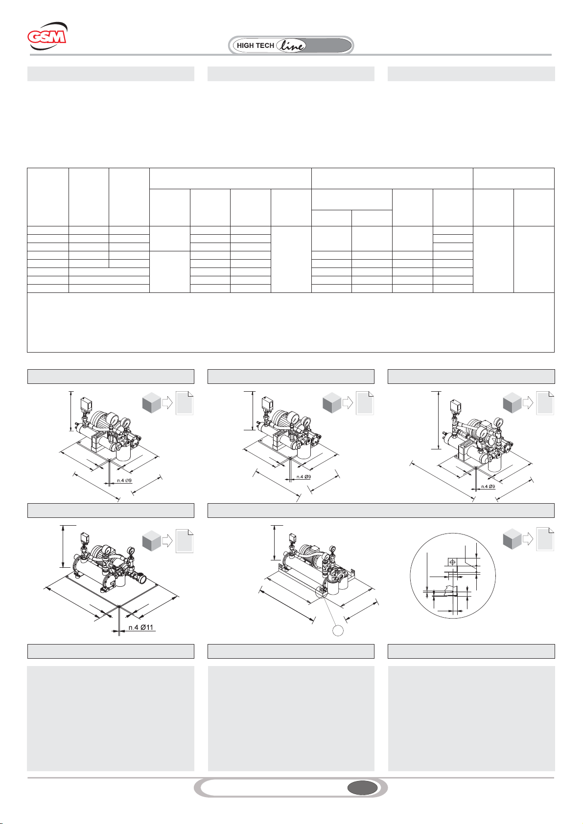
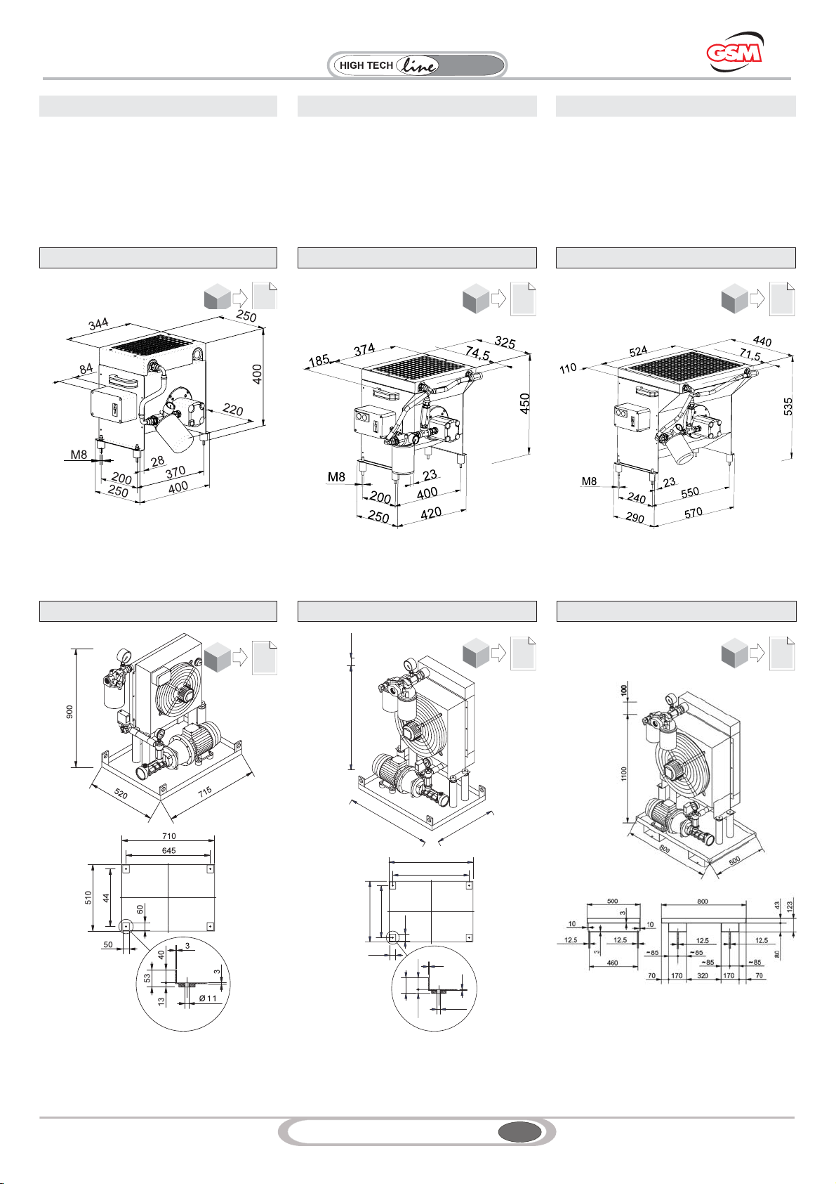
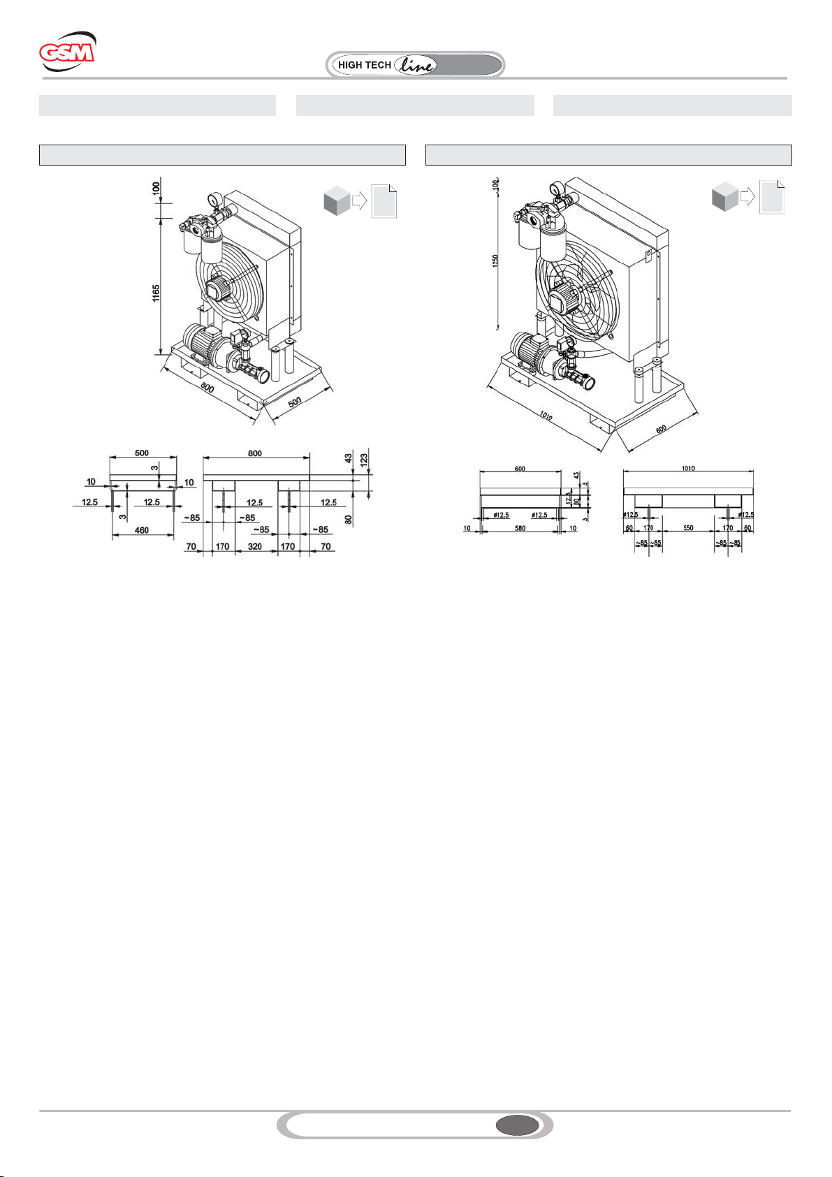
3.3.4 Dimensioni
Nelle tabelle sottostanti sono riportati gli
ingombri dei gruppi:
- SCHEMA A: RFA 1, RFA 2, RFA3;
- SCHEMA B: RFA 3, RFA 4, RFA5;
3.3.4 Maße
In den nachstehenden Tabelle werden die
Maße der Aggregate angegeben:
- SCHEMA A: RFA 1, RFA 2, RFA3;
- SCHEMA B: RFA 3, RFA 4, RFA5;
3.3.4 Dimensions
The tables below show units overall dimensions:
- DIAGRAM A: RFA 1, RFA 2, RFA3;
- DIAGRAM B: RFA 3, RFA 4, RFA5;
RFA 2 RFA 3-A
RFA 1
SCHEMA A DIAGRAM A SCHEMA A
RFA 2RFA 2
39
2D
2D
2D
40
2D
2D
2D
40
2D
2D
2D
SCHEMA B DIAGRAM B SCHEMA B
510
440
53 60
50
40
645
710
710
510
910 100
13
Ø11
3
3
41
2D
2D
2D
42
2D
2D
2D
43
2D
2D
2D
RFA 3-B RFA 4 RFA 5
10
GSM_mod.MT02 IGBD 0.3
RX
Series
Riduttori
Industrial
3. SCOPE OF THE SUPPLY 3. LIEFERZUSTAND3. STATO DI FORNITURA
RFA 6 RFA 7
44
2D
2D
2D
45
2D
2D
2D
11
GSM_mod.MT02 IGBD 0.3
RX
Series
Riduttori
Industrial
4. LIFTING AND HANDLING 4. HEBEN UND TRANSPORT4. SOLLEVAMENTO TRASPORTO
Il sollevamento ed il trasporto dell’unità devono
essere eseguiti con prudenza per evitare
pericolose cadute o ribaltamenti. Per il trasporto
si può utilizzare un carrello a forche d’adeguata
portata.
Attenzione:
Non sollevare l’unità legando funi o cavi a
qualsiasi parte di essa ma utilizzare gli appositi
golfari posti sul basamento o, in alternativa,
usare un carrello elevatore.
Das Heben und der Transport der Einheit
müssen mit besonderer Sorgfalt erfolgen, so
dass ein mit Gefahren verbundenes Umfallen
oder Umkippen vermieden werden können. Für
den Transport kann ein Gabelstapler mit ange-
messener Tragfähigkeit verwendet werden.
Achtung:
Zum Heben der Einheit keine an irgendwelche
Bestandteile angeschlagene Seile oder Kabel
heben, sondern dazu die am Gestell vorgese-
henen Transportösen verwenden oder, als
Alternative, einen Hubwagen verwenden.
The unit must be lifted and handled carefully to
avoid dangerous tilting or fall of the unit. It is
possible to use a fork lift truck of suitable
capacity for handling the unit.
Notice:
Do not lift the unit by means of ropes or cables
attached randomly on the unit; only use the
suitable eyebolts located on the bedplate or use
a lift truck.
5. STOCKING 5. EINLAGERUNG5. STOCCAGGIO
Nel caso in cui si dovrà immagazzinare la
macchina durante lunghi periodi d’inattività, si
raccomanda di custodirla in un locale coperto e
privo d’agenti chimici aggressivi, non
sovrapponendo niente all’imballaggio originale.
Immagazzinamento: l’ambiente deve essere
sufficientemente pulito, secco, esente da
vibrazioni (per non danneggiare i supporti
antivibranti).
Sollte die Maschine während länger
andauernden Stillstandzeiten eingelagert
werden sollen, wird empfohlen, sie in einem
überdachten Bereich abstellen, der keinen
aggressiven chemischen Einflüssen unterliegt.
Dabei nichts auf die Originalverpackung
aufstapeln.Einlagerung: Die Umgebung muss
ausreichend sauber, trocken, frei von
Schwingungen sein (um die
Schwingungsdämpferfüße nicht zu
beschädigen). Heber.
If the machine is to be stocked for long periods of
inactivity, it is recommended to keep it indoors, in
a room with no aggressive chemical agents; do
not pile up anything over the original package.
Stocking: the room shall be clean, dry, free of
vibrations (so that vibration dampers are not
damaged).
6. TYPES OF COMMISSIONING
PROCEDURES
6. INBETRIEBSETZUNGSARTEN6. TIPOLOGIE MESSA SERVIZIO
6.1 CLASSIFICAZIONE
Prima di fornire le istruzioni di installazione e
messa in servizio dei gruppi è necessario
premettere le tipologie di messa in servizio alle
quali si troveranno ad operare i gruppi in modo
da definire il corretto LAYOUT della macchina.
In questo modo è possibile procedere alla
installazione del gruppo e richiedere l’eventuale
fornitura di accessori.
I gruppi di raffreddamento sono utilizzati per due
tipologie di applicazioni:
1– Raffreddamento del riduttore;
2– Raffreddamento del riduttore e lubrificazione
forzata dei cuscinetti/ingranaggi.
E’ necessario conoscere inoltre anche la
temperatura ambiente e la tipologia di olio
utilizzato per la lubrificazione del riduttore.
Attenersi pertanto alla tabella sottostante ed
individuare la tipologia di avviamento a cui è
necessario fare riferimento.
6.1 KLASSIFIKATION
Bevor wir Ihnen die Anleitungen für die Installa-
tion und die Inbetriebnahme der Aggregate
übermitteln, möchten wir Sie über die Inbetrieb-
setzungsarten der Aggregate informieren, so
dass Sie das korrekte LAYOUT der Maschine
bestimmen können. Dies ermöglicht die Instal-
lation des Aggregats und ein Anfordern einer
eventuell erforderlichen Zubehörlieferung.
Die Kühlaggregate werden für zwei Appli-
kationsarten verwendet:
1– zur Kühlung des Getriebes;
2– zur Kühlung des Getriebes und
Zwangsschmierung der Lager/Zahnräder.Dar-
über hinaus muss man die Umgebungstem-
peratur und die für die Schmierung des Getrie-
bes verwendete Ölsorte kennen.
Diesbezüglich muss man sich an die Angaben
in den nachstehenden Tabellen halten und die
Anlaufart zu bestimmen, auf die Bezug genom-
men werden soll.
6.1 CLASSIFICATION
Before detailing installation and commissioning
instructions, it is important to explain the types of
commissioning procedures for these units so as
to define the machine correct LAYOUT. It is then
possible to move on to unit installation and
request any possible accessories.
The cooling units are used for two applications:
1– Gearbox cooling;
2– Gearbox cooling and forced lubrication of
bearings/gears.
It is also important to be aware of the ambient
temperature and of the type of oil used for
lubricating the gearbox.
Please follow the specifications given in the table
below and find the type of commissioning
procedure you need to refer to.
TIPOLOGIE MESSA IN SERVIZIO
TYPES OF COMMISSIONING PROCEDURE
INBETRIEBSETZUNGSARTEN
Temperatura Ambiente
Ambient Temperature
Umgebungstemperatur
>15°C <15°C >10°C <10°C
Applicazione
Tipo Olio
Application Type of Oil
Applikation Ölsorte
Raffreddamento (R)
Cooling (R)
Kühlung (R)
R1R2R1R2
Lubrificazione Forzata (L)
Forced Lubrication (L)
Zwangsschmierung (L)
L1L2L1L2
Viscosità ISO VG olio
Oil ISO VG grade
Viskosität ISO VG Öl
Olio sintetico PAO: ISO VG 220, 320
PAO synthetic oil: ISO VG 220, 320
Synthetiköl PAO: ISO VG 220, 320
Olio sintetico PAO: ISO VG 150
PAO synthetic oil: ISO VG 150
Synthetiköl PAO: ISO VG 150

12
GSM_mod.MT02 IGBD 0.3
RX
Series
Riduttori
Industrial
6. TYPES OF COMMISSIONING
PROCEDURES
6. INBETRIEBSETZUNGSARTEN6. TIPOLOGIE MESSA SERVIZIO
6.2 DESCRIZIONE TIPOLOGIE MESSA IN
SERVIZIO
Nel presente paragrafo si descrivono le deverse
tipologie di avviamento indicando al contempo
gli accessori che è necessario prevedere nel
sitema idraulico per la regolare Messa in Servizio
dell'impianto.
1 - Tipo R1
E’ possibile avviare la motopompa
contemporaneamente al riduttore.
2 - Tipo L1
Avviare la motopompa circa 1 (uno) minuto
prima della messa in marcia del riduttore per
garantire la lubrificazione degli organo
meccanici.
3 - Tipo R2
Vedere schema idraulico al paragrafo 8.1.
E’ indispensabile prevedere un strumento del
tipo TRI provvisto di sonda e termostato
incorporati all'interno del medesimo strumento.
Si consiglia di tarare il termostato in ON a 60
°C.
In modo tale la motopompa entrerà in funzione a
circa 60 °C.
4 - Tipo L2
Vedere schema idraulico al paragrafo 8.2
In questa tipologia di avviamento è necessario
garantire la lubrificazione agli organi meccanici.
Pertanto prima della messa in servizio
dell’impianto è necessario:
1 - Riscaldamento Olio;
2 - Avviamento sistema di lubrificazione.
1 - Riscaldamento Olio
E' necessario utilizzare una scandaglia (SC) e un
dispositivo di segnalazione del tipo TRI 2.
Dimesionamento SC
La scandiglia va dimensionata in funzione del
quantità olio, temperatura ambiente, tempo di
riscaldamento richiesto per la messa in servizio
dell'impianto.
Dimensionamento TRI 2
Si consiglia di tarare il dispositivo con le
seguenti modalità
Regolazione del termostato in OFF a 30 °C;
2 - Avviamento sistema di lubrificazione
E' necessario dare il consenso all’avviamento
del motopompa prevedendo un dispositivo di
segnalazione del tipo TRI 1
Regolazione del termostato in ON a 20 °C;
Si consiglia di ritardare avviamento del motore
del riduttore di circa 1 (uno) minuto rispetto al
motore del gruppo in modo che sia garantita la
lubrificazione dei componenti meccanici.
Nello schema riportato alla pagina seguente è
possibile in funzione del tipo di avviamento e
della tipologia del gruppo di raffreddamento
definire in modo grafico gli accessori da
prevedere nel sistema idraulico e il Sistema di
Controllo da predisporre per la Messa in Servizio
dell'Impianto.
6.2 BESCHREIBUNG DER
INBETRIEBSETZUNGSARTEN
In diesem Paragraph werden die unterschiedli-
chen Anlaufarten unter Angabe des Zubehörs
beschrieben, das im hydraulischen System für
die reguläre Inbetriebnahme der Anlage vorge-
sehen werden muss.
1 - Typ R1
Die Motorpumpe kann gleichzeitig mit den Ge-
triebe gestartet werden.
2 - Typ L1
Die Motorpumpe ungefähr 1 (eine) Minute vor
der Inbetriebsetzung des Getriebes hochfahren,
so dass die Schmierung der mechanischen
Organe gewährleistet wird.
3 - Typ R2
Siehe Hydraulikschema im Paragraph 8.1.
Hier ist es erforderlich ein Instrument vom Typ
TRI vorzusehen, dass mit einer im Instrument
selbst enthaltenen Sonde und einem Thermo-
stat ausgestattet ist.
Es wird empfohlen, das Thermostat in ON
auf 60 °C einzustellen.
In dieser Weise schaltet sich die Motorpumpe
bei einer Temperatur von circa 60 °C ein.
4 - Typ L2
Siehe Hydraulikschema im Paragraph 8.2.
In dieser Anlaufart muss den mechanischen
Organen die Schmierung gewährleistet werden.
Daher ist vor der Inbetriebsetzung der Anlage
folgendes erforderlich:
1 - Erwärmen des Öls
2 - Starten des Schmiersystems.
1 - Erwärmen des Öls
Der Einsatz eines Lots (SC) und einer Anzeige-
vorrichtung vom Typ TRI 2 sind erforderlich.
Bemaßung SC
Das Lot muss in Abhängigkeit der Ölmenge,
der Umgebungstemperatur und der Aufheizzeit
bemaßt werden, die für die Inbetriebnahme der
Anlage erforderlich ist.
Bemaßung TRI 2
Es wird empfohlen, die Anlage wie folgt einzu-
stellen
Einstellung des Thermostats in OFF auf 30 °C
2 - Starten des Schmiersystems.
Es ist erforderlich den Anlauf der Motorpumpe
freizugeben, dazu ist eine Anzeige des Typs
TRI 1 vorzusehen.
Einstellung des Thermostats in ON auf 20 °C
Es wird empfohlen, den Anlauf des Motors des
Getriebes um ca. 1 (eine) Minute gegenüber
dem Anlauf des Motors des Aggregats zu ver-
zögern, so dass die Schmierung der mechani-
schen Komponenten gewährleistet werden
kann.
Im auf der nachstehenden Seite wiedergegebe-
nen Schema kann in Abhängigkeit zur Anlaufart
und dem Typ des Kühlaggregats die im Hydrau-
liksystem und im Steuersystem für die Inbe-
triebnahme der Anlage vorzusehenden
Zubehörteile in grafischer Form zu bestimmen.
6.2 DESCRIPTION OF COMMISSIONING
PROCEDURES
This chapter describes the various types of
commissioning procedures and indicates the
accessories that the hydraulic system should
have fitted to ensure the correct system
Commissioning.
1-R
1Type
It is possible to start the motor pump at the same
time as the gearbox.
2-L
1Type
Start the motor pump about 1 (one) minute
before starting the gearbox to ensure lubrication
of the mechanical organs.
3-R
2Type
See hydraulic diagram in chapter 8.1.
It is indispensable to use an instrument of the TRI
type with built-in probe and thermostat.
It is recommended to calibrate the thermostat
ON value at 60 °C.
In this way the motor pump will start operating at
about 60 °C.
4-L
2Type
See hydraulic diagram in chapter 8.2.
In this type of commissioning procedure it is
necessary to ensure mechanical organs
lubrication.
This is why the following steps shall be
performed before operating the system:
1 - Warming up oil;
2 - Starting the lubrication system.
1 - Warming up oil
It is necessary to use a sounding machine (SC)
and a signalling device of the TRI 2 type.
SC size
Choose suitably sized sounding machine
according to oil quantity, ambient temperature,
required warm-up time for system operation.
TRI 2 size
It is recommended to calibrate the device as
follows
Set thermostat OFF value at 30 °C;
2 - Starting the lubrication system
It is necessary to enable motor pump start-up by
means of a signalling device of the TRI 1 type.
Set thermostat ON value at 20 °C;
It is recommended to delay the gearbox start-up
by about 1 (one) minute with respect to unit
motor so that mechanical components
lubrication is assured.
The diagram on next page allows you to identify
the accessories to be fitted to the hydraulic
system and the Control System to be used for
System Commissioning, according to the type of
commissioning procedure and type of cooling
unit.
13
GSM_mod.MT02 IGBD 0.3
RX
Series
Riduttori
Industrial
ATTENZIONE
1 - Le schede tecniche dei prodotti elencati sono
disponibili al paragrafo accessori.
2 - Per le tipologie di messa in servizio si
consiglia di impiegare eventualemente un
dispositivo di sicurezza composto da un
termostato bimetallico TB la cui soglia di
interventoèa90°C.
3 - Per quanto riguarda i gruppi di
raffreddamento RFA è necessario puntualizzare
quanto segue:
SCHEMA A:
In questa configurazione una volta avviata la
motopompa si avvia anche il ventilatore.
In particolare il gruppo RFA3 già fornito con i
seguenti accessori:
- termostato (T1)
- sonda per rilevamento della temperatura (TC1)
Tali accessori son equilvalenti a quello sopra
riportato con la sigla TRI 1.
SCHEMA B:
In questa configurazione è possibile regolare la
temperatura di intervento ON alla quale fare
avviare il motoventilatore in modo indipendente
alla motopompa sgendo sul termostato di
regolazione (T0).
ACHTUNG
1 - Die technischen Datenblätter der aufgeliste-
ten Produkte werden im nachstehenden Para-
graph “Zubehör” wiedergegeben.
2 - Bei allen Inbetriebssetzungsarten wird em-
pfohlen eventuell eine Sicherheitsvorrichtung
einzusetzen, die in einem Bimetall-Thermostat
TB besteht, deren Auslöseschwelle 90 °C
beträgt.
3 - Was die Kühlaggregate RFA anbelangt, ist
folgendes anzumerken:
SCHEMA A :
In dieser Konfiguration, läuft mit dem Start der
Motorpumpe auch der Ventilator an. Das
Aggregat RFA3 wird bereits mit folgendem Zu-
behör geliefert:
- Thermostat (T1)
- Sonde für die Temperaturmessung (TC1)Die-
ses Zubehör entspricht den oben, unter der Be-
zeichnung TRI 1 angegebenen Teilen.
SCHEMA B:
In dieser Konfiguration kann am Regelthermo-
stat (T0) die Auslösetemperatur ON reguliert
werden, bei es von der Motorpumpe
unabhängig zum Anlauf des Motorventilator
kommen soll.
NOTICE
1 - The technical data sheets for any listed
product are available under the accessories
chapter.
2 - For all commissioning procedure types it is
recommended to use, if necessary, a safety
device consisting of a TB bimetallic thermostat
with tripping value set at 90 °C.
3 - As far as RFA cooling units are concerned, it
is necessary to be aware that:
DIAGRAM A:
In this configuration the fan starts once motor
pump starts. In particular, RFA3 unit already
comes with the following accessories:
- thermostat (T1)
- temperature probe (TC1)
These accessories are the same as the device
above indicated with TRI 1.
DIAGRAM B:
In this configuration, it is possible to adjust ON
temperature value, i.e. the temperature at which
the motor fan starts, independently with respect
to the motor pump, by turning adjustment
thermostat (T0).
6. TYPES OF COMMISSIONING
PROCEDURES
6. INBETRIEBSETZUNGSARTEN6. TIPOLOGIE MESSA SERVIZIO
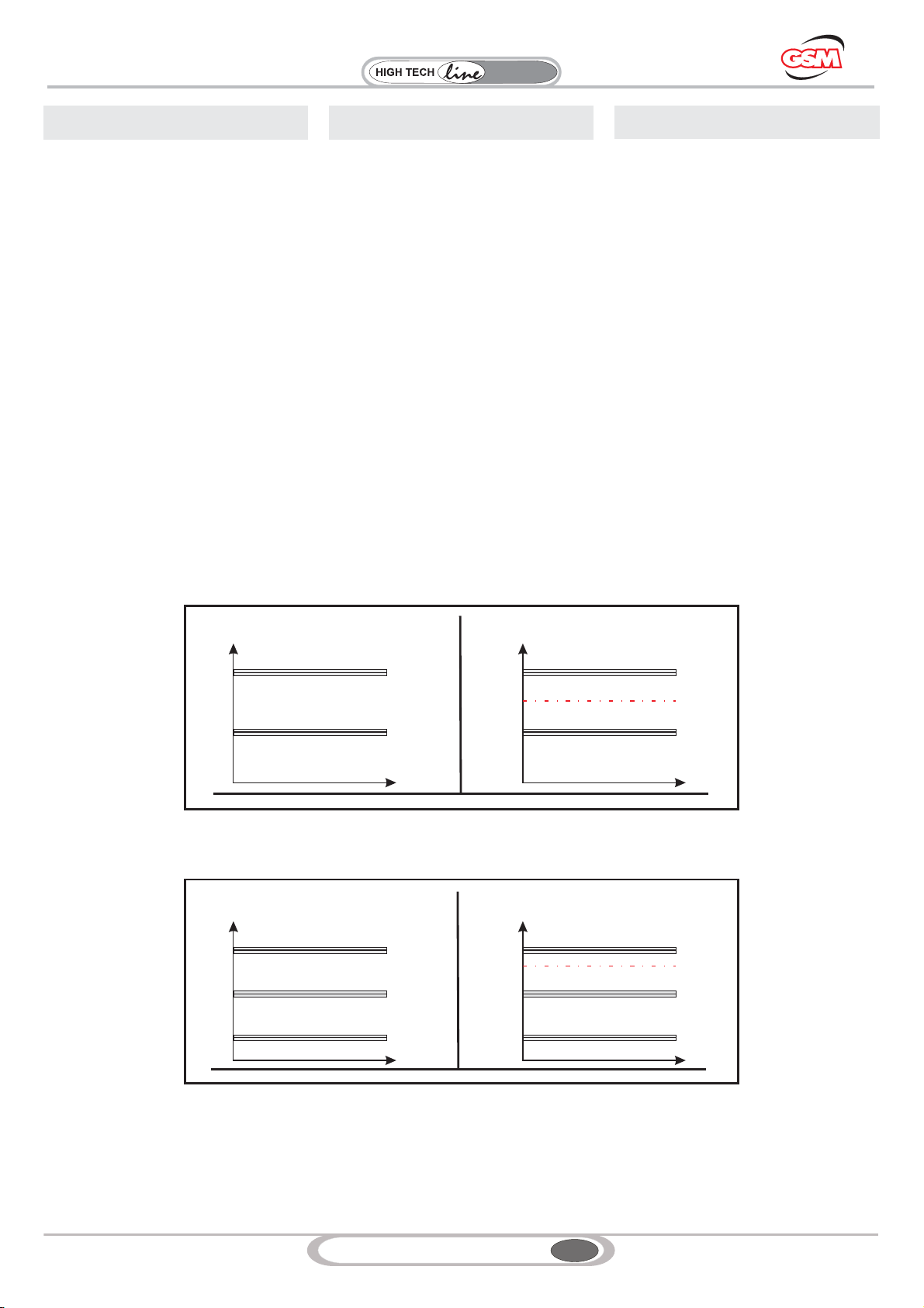
On
Off
60 °C TRI 1
90 °C TB
Off
Off
On
30 °C TRI 2
90 °C TB
Off
On
Off
20 °C TRI 1
Off
On
30 °C TRI 2
90 °C TB
Off
On
Off
20 °C TRI 1*
60 °C
TIPO- -TYP
R2
TYPE
On
Off
60 °C TRI 1*
90 °C TB
Off
RFW RFA
60 °C T0**
RFW RFA
T0**
RFW RFA
TIPO- -TYP
L2
TYPE
NOTE
* nel caso Schema A - RFA3
il controllo è fornito Standard con Sensore Tc1 e termostato T1
** Nei gruppi del tipo Schema B -RFA3, RFA4, RFA5
ATTENZIONENEL TIPO AVVIAMENTO L2 prevedere a
ritardare avviamento del motore del riduttore1 (uno) minuto
rispetto al motore del gruppo in modo che sia garantita la
lubrificazione dei componenti meccanici
NOTE
* in case shown in Diagram A - RFA3 the control is supplied as
Standard with Sensor Tc1 and thermostat T1
** In units of the type shown in Diagram B -RFA3, RFA4, RFA5
NOTICE FOR L2 COMMISSIONING PROCEDURE delay the
gearbox motor start-up by 1 (one) minute with respect to unit
motor so that mechanical components lubrication is assured.
HINWEISE
* Im Schema A - RFA3 handelt es sich um eine Standardsteue-
rung mit Sensor Tc1 und Thermostat T1** Bei Aggregaten des
Typs gemäß B -RFA3, RFA4, RFA5
ACHTUNG, BEI DER ANLAUFART L2 Den Anlauf des Motors
des Getriebes um 1 (eine) Minute gegenüber dem Anlauf des
Motors des Aggregats verzögern, so dass die Schmierung der
mechanischen Komponenten gewährleistet werden kann.

14
GSM_mod.MT02 IGBD 0.3
RX
Series
Riduttori
Industrial
7.1 LUOGO DI FUNZIONAMENTO
Le unità RFA devono essere installate in modo
che l’aria non sia ostacolata nel suo fluire sia in
aspirazione che all’uscita dal pacco radiante.
Per un’ottimale resa termica dell’unità è da
evitare qualsiasi riciclaggio d’aria calda tra uscita
aria e aspirazione.
Le unità RFW non prevedono particolari
prescrizioni.
7.2 LUOGO CHIUSO E/O POLVEROSO
E’ indispensabile che nel locale in cui siano
installate le unità RFA esista un ricambio d’aria
sufficiente in modo che l’aria stessa non venga
riscaldata pregiudicando la resa termica dello
scambiatore.La temperatura massima
dell’ambiente non deve superare i 40 °C,
viceversa è pregiudicata la resa termica
dell’unità.
L’installazione delle unità RFA in un ambiente
molto polveroso provoca un’otturazione del
pacco radiante e quindi un calo di resa termica.
E’ per questo che in un ambiente polveroso o
saturo d’olio e’ indispensabile mantenere pulito il
pacco radiante con una pulizia regolare (vedi
manutenzione).
Le unità RFW non prevedono particolari
prescrizioni.
7.3 INSTALLAZIONE IN LUOGO APERTO
In questo caso l’unità deve essere protetta dalle
intemperie; prevedere quindi una tettoia, in modo
che essa non risulti esposta direttamente
all’acqua piovana.
In inverno, nel caso di fermo macchina
prolungata, la temperatura dell’olio diventa molto
bassa e quindi aumenta di molto la sua viscosità
(prima della messa in servizio attenersi alle
indicazioni riportate nei capitoli 6.0 e 8.0.
7.4 ILLUMINAZIONE
Il luogo d’installazione della macchina deve
avere un’illuminazione naturale e/o artificiale
conforme alla normativa vigente, in ogni caso
sufficiente a compiere eventuali operazioni di
manutenzione o riparazione.
7.5 FISSAGGIO DEL GRUPPO
Il fissaggio deve essere fatto utilizzando i fori di
fissaggio previsti sulle basi.
Vedere il punto 3.0 (STATO DI FORNITURA).
7.6 COLLEGAMENTO IMPIANTO IDRAULICO
Le unità di raffreddamento devono essere
collegate al serbatoio dell’olio utilizzando dei tubi
flessibili tipo SAE 100 R1 con raccordi gas
adeguati oppure con tubi rigidi ma con interposto
un manicotto flessibile.
E’ indispensabile che il tubo d’aspirazione sia di
diametro uguale o superiore a quello del
raccordo esistente sul gruppo; in caso contrario
si potrebbero verificare fenomeni di cavitazione
che causerebbero rumorosità elevata e cattivo
funzionamento della pompa.Per lo stesso motivo
e per evitare anche perdite di carico inutili e/o
dannose si consiglia di non far percorrere ai tubi
di collegamento percorsi tortuosi, riduzioni di
diametri, ecc...
Nel caso si debba montare l’unità sopra il livello
dell’olio, l’impiego della pompa a vite consente di
collocarla ad un altezza massima di due metri tra
la pompa ed il pelo libero dell’olio, la pompa ad
ingranaggi non deve superare i 50 cm.
Ad altezze superiori la pompa potrebbe cavitare.
L’aspirazione della pompa va collegata ad un
foro di scarico del serbatoio.
Se necessario si può interporre un raccordo a T
per poter scaricare l’olio senza scollegare il
tubo.La mandata dello scambiatore va collegata
ad un altro foro ricavato sul serbatoio in
posizione più alta possibile oppure al
collettore.Nel paragrafo 3.0 sono riportati gli
attacchi dei Gruppi RFA e RFW mentre nella
tabella sottostante è fornita una tabella nella
quale sono riportati i fori presenti sulle casse dei
riduttori e il loro posizionamento.
7.1 INSTALLATIONSORT
Die Einheiten RFA müssen so installiert wer-
den, dass der Luftfluß weder in der Ansaugung
noch im Ablass aus der Kühleinheit behindert
wird.Für einen optimalen Wärmeaustausch der
Einheit sollte jegliches Recycling der Warmluft
zwischen Luftablass und -ansaugung vermie-
den werden. Die Einheiten RFW unterliegen ke-
inen besonderen Vorschriften.
7.2 GESCHLOSSENER UND/ODER
STAUBIGER INSTALLATIONSORT
Der Raum, in dem die Einheiten RFA installiert
werden sollen, muss einen ausreichenden Luft-
austausch haben, so dass vermieden wird,
dass sich die Luft aufheizt und so die Leistung
des Wärmeaustauschers verringert. Die max.
Umgebungstemperatur darf 40 °C nicht über-
schreiten, andernfalls wird die Austragsleistung
der Einheit negativ beeinflusst. Die Installation
der Einheiten RFA in einem stark mit Staub be-
lasteten Umfeld erzeugt das Verstopfen des
Kühlrippenpakets und führt zu einer geringeren
thermischen Leistung. Daher ist es in einer
staubigen oder mit Öl gesättigten Umgebung
unbedingt erforderlich das Kühlrippenpaket
regelmäßig zu reinigen (siehe Instandhaltung).
Die Einheiten RFW unterliegen keinen beson-
deren Vorschriften.
7.3 INSTALLATION IM FREIEN
In diesem Fall muss die Einheit vor Wetter-
einflüssen geschützt werden. Dazu eine Über-
dachung vorsehen, so dass sie dem Regen
nicht direkt ausgesetzt resultiert. Im Winter,
falls die Maschine länger stillstehen sollte, sinkt
die Öltemperatur stark ab und seine Viskosität
stark zu (vor der Inbetriebnahme müssen die
Angaben in den Kapiteln 6.0 und 8.0 befolgt
werden).
7.4 BELEUCHTUNG
Der Installationsort der Maschine muss
natürlich/künstlich der geltenden Richtlinie kon-
form beleuchtet sein. Die Beleuchtung muss
ausreichen, um eventuelle Instandhaltungs-
oder Reaparaturarbeiten ausführen zu können.
7.5 BEFESTIGUNG DES AGGREGATS
Die Befestigung muss über die an den Gestel-
len vorgesehenen Bohrungen erfolgen.
Siehe Punkt 3.0 (LIEFERZUSTAND).
7.6 ANSCHLUSS DES HYDRAULIKSYSTEMS
Die Kühleinheiten müssen über Schläuche von
Typ SAE 100 R1 mit angemessenen Gasan-
schlüssen oder über Rohre mit zwischengesetzter
flexibler Muffe mit dem Ölbehälter verbunden wer-
den. Es ist erforderlich, dass die Ansaugleitung im
Vergleich zum am Aggregat vorhandenen
Anschluss den gleichen oder einen größeren
Durchmesser hat; sollte dies nicht der Fall sein,
kann es zu Hohlraumbildungen kommen, die zu
starken Geräuschen und Funktionsstörungen der
Pumpe führen können. Aus dem selben Grund und
um unnütze bzw. schadhafte Belastungen zu ver-
meiden, wird empfohlen, die Verbindungsleitungen
möglichst direkt, ohne zahlreiche Windungen, zu
verlegen und Durchmesserreduzierungen, usw. zu
vermeiden. Sollte die Einheit über dem Ölpegel
montiert werden, ermöglicht der Einsatz der
Schneckenpumpe deren Anordnung in einer max.
Höhe von zwei Metern zwischen Pumpe und Öl-
pegel, die Zahnradpumpe darf 50 cm nicht
überschreiten.In darüber liegenden Höhen,
kann es zu Hohlraumbildungen in der Pumpe
kommen. Die Ansaugung der Pumpe muss an
eine Ablassbohrung des Behälters geschlossen
werden. Ggf. kann ein T-Anschluss zwischen-
gesetzt werden, der den Ölablass ermöglicht,
ohne dass die Leitung dazu gelöst werden
muss. Der Zulauf des Wärmeaustauschers
muss an eine andere Bohrung geschlossen
werden, die in der höchst möglichen Position
am Behälter eingearbeitet ist oder an den Kol-
lektor. Im Paragraph 3.0 werden die Anschlüs-
se der Aggregate RFA und RFW angegeben,
während in der Tabelle die Bohrungen und ihre
Positionen angegeben, wie sie an den Gehäu
sen der Getriebe vorhanden sind.
7.1 INSTALLATION SITE
RFA units must be installed so that air flow is free
from obstacles both at inlet and outlet from
radiator. Avoid any hot air recycling from outlet to
inlet to ensure unit optimum efficiency.
RFW units do not require special provisions.
7.2 ENCLOSED AND/OR DUSTY ROOM
It is indispensable that the room where RFA units
are installed is provided with a sufficient air
circulation so that air does not reach such a
temperature that would jeopardise exchanger
efficiency. Maximum allowed ambient
temperature is 40 °C; above this limit, the unit
efficiency is compromised. Installing the RFA
units in a dusty environment leads to clogging of
the radiator fins resulting in a drop in efficiency.
This is why it is fundamental to regularly clean
the radiator fins in case of dusty environment or
saturated with oil (see maintenance).
RFW units do not require special provisions.
7.3 OUTDOOR INSTALLATION
In this case the unit shall be protected against
weather conditions; set a roofing for this
purpose, so that unit is not under the rain.
In winter, in case of long periods of inactivity, oil
temperature becomes very low and thus its
viscosity is remarkably increased (before
operation, please follow instructions given in
chapters 6.0 and 8.0.)
7.4 LIGHTING
The machine installation site should be naturally
and/or artificially lit, as required by the prevailing
rules, but in any case lit enough to allow for any
maintenance or repair operations.
7.5 FASTENING THE UNIT
Unit shall be fastened by means of the suitable
securing holes located on the bases.
See point 3.0 (SCOPE OF THE SUPPLY).
7.6 HYDRAULIC SYSTEM CONNECTION
The cooling units shall be connected to oil tank
by means of flexible hoses of the SAE 100 R1
type with suitable gas fittings or by means of rigid
pipes but with a hose in-between.
It is indispensable that inlet hose is of the same
diameter as (or larger than) the existing fitting; if
not so, cavitation could result and cause pump
loud noise and malfunction. For the same reason
and to avoid useless and/or harmful flow
resistance it is recommended not to set winding
tube paths, not to have reduction of the tube
diameter, etc.
If the unit is to be mounted above oil level, use a
screw pump so that it can be set at a distance of
maximum two meters from oil surface, while gear
pump can not be mounted farther than 50 cm
from oil surface. Cavitation could occur if pump is
installed at a bigger distance. Pump inlet shall be
connected to a tank drain hole.
If necessary, a Tee could be used to be able to
drain oil with no need to disconnect the tube.
Exchanger delivery shall be connected to
another hole drilled on tank at the farther top
position or to the manifold. Chapter 3.0 shows
RFA and RFW units layout while the table below
indicates the holes available on gearbox cases.
7. INSTALLATION 7. INSTALLATION7. INSTALLAZIONE
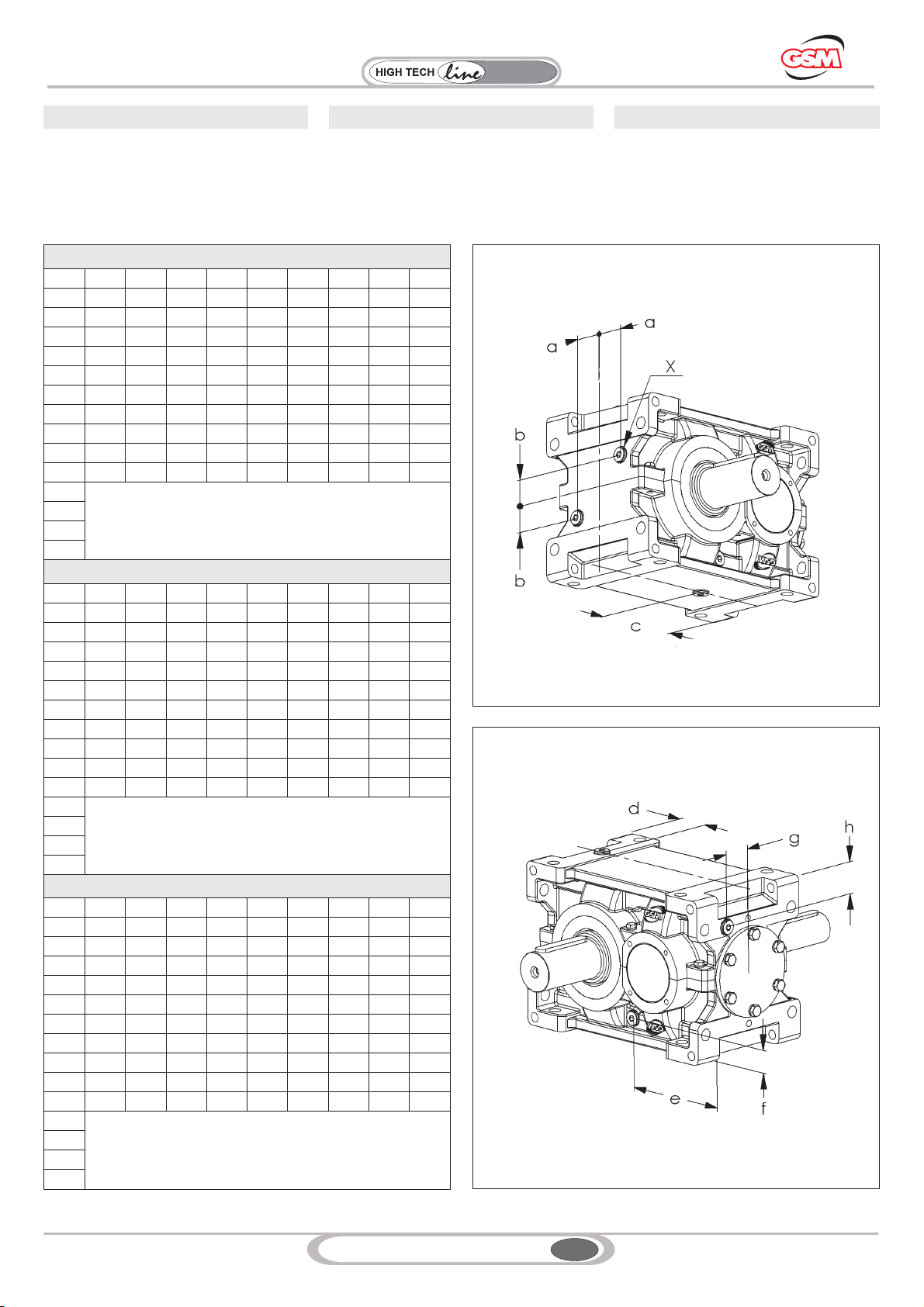
15
GSM_mod.MT02 IGBD 0.3
RX
Series
Riduttori
Industrial
7.7 POSIZIONE TAPPI
ATTENZIONE
La fornitura dei tappi in posizione diverse da
quelle riportate va concordata con Ufficio
Commerciale.
7.7 ANORDNUNG DER STOPFEN
ACHTUNG
Die Lieferung der Stopfen in von den
angegebenen Stopfen abweichenden
Positionen muss mit unserer Handelsabteilung
abgestimmt werden.
7.7 PLUGS POSITION
NOTICE
Agree with our Sales Department the supply of
plugs at different positions than indicated.
7. INSTALLATION 7. INSTALLATION7. INSTALLAZIONE
RXP1/RXO1/RV1
Xabcde f gh
802 G 3/8 45 40 140 51 173 35 45 49
804 G ½ 50 45 157 60 190.5 42.5 50 54.5
806 G ½ 55 50 175 70 220 45 55 62.5
808 G ½ 65 60 196 72 250 47 65 70
810 G ¾ 70 63 220 80 274 60 70 85
812 G ¾ 80 70 248 90 313 67.5 80 95
814 G ¾ 85 80 273 101 345 72.5 85 105
816 G 1 105 90 310 119 395 83 105 120
818 G 1 115 100 350 130 440 85 115 123
820 G 1 135 112 392.5 143 495 95 120 138
822
A richiesta / On Request / Auf Anfrage
824
826
828
RXP2/RXO2/RV2
Xabcde f gh
802 G 3/8 45 28 104.5 51 253 35 45 72.5
804 G ½ 50 30 118 60 282,5 42,5 50 78
806 G ½ 55 35 136 70 320 45 55 90
808 G ½ 65 50 154 80 362 47 65 105
810 G ¾ 70 42 171 87 399 60 70 115
812 G ¾ 80 50 194 90 453 67,5 80 132,5
814 G ¾ 85 52 215 110 505 72,5 85 145
816 G 1 105 55 243 120 575 80 105 165
818 G 1 115 60 275 130 640 85 115 185
820 G 1 135 65 310 143 720 95 135 220
822
A richiesta / On Request / Auf Anfrage
824
826
828
RXP3/RXO3/RV3
Xabcde f gh
802 G 3/8 45 20 77.5 51 316 35 45 72.5
804 G ½ 50 22 86 60 352.5 42.5 50 78
806 G ½ 55 27 102 70 400 45 55 90
808 G ½ 65 32 117 80 452 47 65 105
810 G ¾ 70 36 134 80 499 60 70 115
812 G ¾ 80 42 152 90 565 67.5 80 132.5
814 G ¾ 85 45 167 110 630 72.5 85 145
816 G 1 105 55 190 120 715 80 105 165
818 G 1 115 60 210 130 800 85 115 185
820 G 1 135 65 240 143 900 95 135 220
822
A richiesta / On Request / Auf Anfrage
824
826
828
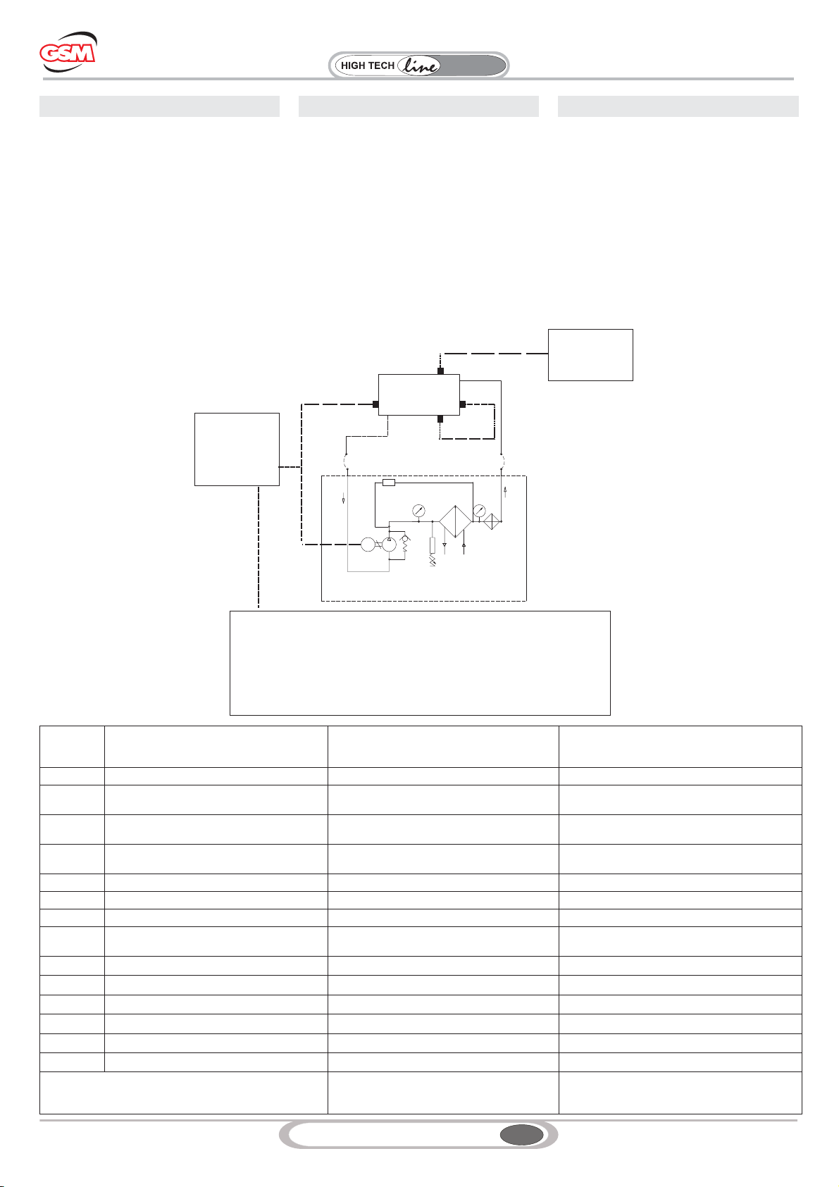
16
GSM_mod.MT02 IGBD 0.3
RX
Series
Riduttori
Industrial
8.1 GRUPPO RFW
Nei prossimi paragrafi saranno fornite le
informazioni per la messa in marcia dei gruppi
RFW.
8.1.1 SCHEMA IDRAULICO
8.1 AGGREGAT RFW
In den ersten Paragraphen werden die für die
Inbetriebsetzung der Aggregate RFW
erforderlichen Informationen gegeben.
8.1.1 HYDRAULIKSCHEMA
8.1 RFW UNIT
The following chapters give any information for
the first start-up of the RFW units.
8.1.1 HYDRAULIC DIAGRAM
8. COMMISSIONING 8. INBETRIEBSETZUNG8. MESSA IN SERVIZIO
D
MP
SS
F
T
r
TRI 1
D
SC
TRI 2
m
TB
m
b
Riduttore
Getriebe
Gearbox
Prevedere
Controllo
Provide for control unit
Steuerung vorsehen
Tipo - Type - Typ
L2
Prevedere
Controllo
Provide for control unit
Steuerung vorsehen
ATTENZIONE
NEL TIPO AVVIAMENTO L2 prevedere a ritardare avviamento del motore del riduttore
1 (uno) minuto rispetto al motore del gruppo in modo che sia garantita la lubrificazione
dei componenti meccanici.
NOTICE
FOR L2 COMMISSIONING PROCEDURE delay the gearbox motor start-up by 1 (one) minute
with respect to unit motor so that mechanical components lubrication is assured
ACHTUNG
BEI DER ANLAUFART L2 muss der Motorstart des Getriebes um 1 (eine) Minute dem Motor des
Aggregats gegenüber verzögert werden, so das die Schmierung der mechanischen Komponenten
gewährleistet werden kann.
SCHEMA IDRAULICO
HYDRAULIC DIAGRAM
HYDRAULIKSCHEMA
RFW
V
Simbolo
Symbol
Symbol
Legenda Legend Legende
b By pass (solo per RFW 3) By-pass (only for RFW 3) Bypass (nur für RFw 3)
D Connessione flessibile (a cura del cliente,
secondo tabella) Flexible connection (at customer's charge,
as per table)
Verbindung über Schlauch (vom Kunden zu
stellen, siehe Tabelle)
F Filtro con indicatore elettrico
d'intasamento Filter with electrical clogging indicator Filter mit elektrischer Verstopfungsanzeige
mManometro 0-16 bar 0-16 bar Pressure gauge Manometer 0-16 bar
M Motore della pompa Pump motor Motor der Pumpe
P Pompa Pump Pumpe
S Scambiatore acqua-olio Water-oil exchanger Wasser-Öl-Wärmeaustauscher
TRI 1 Termostato regolabile per avviamento
motopompa. Adjustable thermostat for motor pump
starting
Regulierbares Thermostat für Anlauf der
Motorpumpe
TRI 2 Termostato regolabile per SET SC Adjustable thermostat for SET SC Regulierbares Thermostat für SET SC
TB Termostato Bimetallico Bimetallic Thermostat Bimetall-Thermostat
SC Scandiglia Sounding machine Lot
TTermometro 0-120 °C 0-120 °C Thermometer Thermometer 0-120 °C
VValvola di sicurezza tarata a 5 bar. Safety valve set at 5 bar Auf 5 bar geeichtes Sicherheitsventil
rPressostato di minima Minimum pressure switch Mindestdruckwächter
Nei gruppi con pompa a vite la valvola di sicurezza è
presente all’interno della pompa stessa In presence of screw pump aggregates the
safety valve is located inside the pump itself
Bei Schraubenpumpen ist das Sicherheitsventil
in der Pumpe vorhanden

17
GSM_mod.MT02 IGBD 0.3
RX
Series
Riduttori
Industrial
8.1.2 SCHEMA ELETTRICO
L’impianto elettrico a bordo dell’unità è realizzato
a cura del cliente.
Esso si limita semplicemente alla realizzazione
di un selettore marcia-arresto della motopompa.
Il collegamento elettrico della motopompa deve
essere eseguito secondo lo schema riportato
all’interno del coperchio motore.
8.1.3 MESSA IN SERVIZIO
1 - Collegamento Impianto idraulico
Vedere paragrafo installazione 7.0
2-Avviamento
Innanzitutto si deve verificare che la tensione e la
frequenza d’alimentazione corrispondano a
quelle indicate sulla targhetta.
Per l’alimentazione elettrica occorre disporre di
tensione alternata trifase, secondo la targa
riportata sui motori.
Controllare che i sensi di rotazione siano
conformi a quelli indicati con freccia autoadesiva
e richiesti dalla pompa.
Dopo aver collegato alla rete elettrica il gruppo,
chiudere la scatola di derivazione e dare
tensione.
Dando tensione si alimenta il gruppo
motopompa.
L’impianto elettrico a bordo macchina e le
eventuali protezioni, sono a cura
dell’installatore.
3 - Controllo
Se l’olio non si stabilizza alla temperatura voluta
ma essa aumenta lentamente e continuamente
con il passare del tempo, è necessario
procedere alle seguenti verifiche per stabilirne la
causa:
1. Velocità e senso di rotazione del gruppo
ventilatore-motopompa.
2. Rumorosità della pompa: se alta siamo in
presenza di fenomeni di cavitazione che sono
assolutamente da evitare.
3. Pulizia del fascio tubiero (possibile formazione
di calcare sul lato acqua).
4. Temperatura d’entrata dell’acqua.
Un sottodimensionamento o un freno alla
circolazione dell’olio e/o dell’acqua o ancora un
intasamento dei condotti sono da evitare per
ottenere un’ottimale resa termica.
8.1.2 SCHALTPLAN
Die elektrische Anlage der Einheit wird vom
Kunden realisiert. Dieser braucht dafür nur
einen Wählschalter für Betrieb-Stopp der
Motorpumpe vorzusehen. Der elektrische
Anschluss der Motorpumpe muss dem
Schaltplan, der an der Innenseite des
Motordeckels angebracht ist, gemäß erfolgen.
8.1.3 INBETRIEBSETZUNG
1 - Anschluss der Hydrauliksystems
Siehe Paragraph 7.0 “Installation”
2- Anlass
Insbesondere muss zunächst einmal überprüft
werden, dass die Versorgungsspannung und
-frequenz mit den Angaben auf dem Schild
übereinstimmen.
Für die elektrische Versorgung muss eine 3-phasi-
ge Wechselspannung, gemäß Angaben auf den
Motorenschildern verfügbar sein.Kontrollieren,
dass die Drehrichtungen denen entsprechend, die
von der Pumpe gefordert werden und die durch
den aufgeklebten Pfeil angegeben werden. Nac-
hdem das Aggregat an die Stromversorgung an-
geschlossen wurde, den Abzweigkasten schließen
und Spannung zugeben.Durch die Zuschaltung
der Spannungsversorgung wird das Aggregat der
Motorpumpe versorgt. Die elektrische Anlage der
Maschine und die eventuell vorgesehenen Schut-
zvorrichtungen sind vom Installateur vorzusehen.
3 - Kontrolle
Stabilisiert sich das Öl nicht auf der
gewünschten Temperatur, sondern steigt
langsam und kontinuierlich im Laufe der Zeit
an, sind für das Feststellen der Ursache
folgende Kontrollen erforderlich:
1. Geschwindigkeit und Drehrichtung des
Aggregats Ventilator-Motorpumpe.
2. Geräuschpegel der Pumpe: Ist er hoch
haben sich Hohlräume gebildet, was absolut zu
vermeiden ist.
3. Verschmutzungszustand der Rohrbündels
(mögliche Kalkablagerungen auf der Seite des
Wassers).
4. Temperatur des einlaufenden Wassers.
Eine Unterbemaßung oder eine Drosselung des
Öls und/oder des Wasserflusses sowie eine
Verstopfung der Kanäle sind im Sinne eines
Erhalts einer optimalen thermischen Leistung
zu vermeiden.
8.1.2 WIRING DIAGRAM
On-board electric system is at customer’s
charge. It simply consists of a start-stop switch
for the motor pump. Motor pump electrical
connection shall comply with the diagram affixed
inside the motor cover.
8.1.3 COMMISSIONING
1 - Connecting the hydraulic system
See chapter 7.0 installation
2-Start-up
First of all check that power voltage and
frequency comply with values indicated on
identification plate.
Power supply shall be three-phase alternated
current, as specified on the motor plate. Ensure
that direction of rotation complies with the one
indicated by arrow and required by pump.
After connecting the unit to the mains, close the
connector block and power on to energise the
motor pump assembly.
On-board electric system and any protections
are care of the installing personnel.
3 - Inspection
If oil temperature does not settle to desired value
and slowly and continuously increases in time, it
is necessary to perform the following checks to
determine the cause:
1. Speed and direction of rotation of the
fan-motor pump assembly.
2. Pump noise level: if too high, cavitation might
be occurring and should absolutely be avoided.
3. Tube bundle cleaning (limestone has possibly
formed on water side).
4. Water inlet temperature.
To assure optimum efficiency, avoid undersized
components or anything that might hamper oil
and/or water circulation or even clog ducts.
8. COMMISSIONING 8. INBETRIEBSETZUNG8. MESSA IN SERVIZIO

18
GSM_mod.MT02 IGBD 0.3
RX
Series
Riduttori
Industrial
D
MP
SS
F
r
TRI 1
Riduttore
Getriebe
Gearbox
D
SC
D
MP V
S
MV
S
F
T
r
D
T0
MV
Attenzione
SulGruppoRFA3icomponentiTC1eT1sono
forniti come standard
Notice
RFA3 unit is supplied as standard with TC1 and
T1 components
An der Gruppe RFA3 gehören die Komponenten Tc1
und T1 zum Standard-Lieferumfang
TRI 2
TRI 1 SC
TRI 2
SCHEMA IDRAULICO
HYDRAULIC DIAGRAM
HYDRAULIKSCHEMA
RFA
mm
b
TB Prevedere
Controllo
Provide for control unit
Steuerung vorsehen TB
ATTENZIONE
NEL TIPO AVVIAMENTO L2 prevedere a ritardare avviamento del motore del riduttore
1 (uno) minuto rispetto al motore del gruppo in modo che sia garantita la lubrificazione
dei componenti meccanici.
NOTICE
FOR L2 COMMISSIONING PROCEDURE delay the gearbox motor start-up by 1 (one) minute
with respect to unit motor so that mechanical components lubrication is assured
ACHTUNG
BEI DER ANLAUFART L2 muss der Motorstart des Getriebes um 1 (eine) Minute dem Motor des
Aggregats gegenüber verzögert werden, so das die Schmierung der mechanischen Komponenten
gewährleistet werden kann.
TC 1
T1
SCHEMA A
DIAGRAM A
SCHEMA A
SCHEMA B
B
DBIAGRAM
SCHEMA
Riduttore
Getriebe
Gearbox
Prevedere
Controllo
Provide for control unit
Steuerung vorsehen
Prevedere
Controllo
Provide for control unit
Steuerung vorsehen
Tipo - Type - Typ
L2
8.2 RFA-AGGREGAT
In den ersten Paragraphen werden die für die
Inbetriebsetzung der Aggregate RFA
erforderlichen Informationen gegeben.
Es muss überprüft werden, ob das Aggregat
dem Schema A oder dem Schema B zuzu-
ordnen ist, dazu ist Bezug auf den Par. 3.0
(Lieferzustand) zu nehmen.
8.2.1 HYDRAULIKSCHEMA
8.2 RFA UNIT
The following chapters give any information for
the first start-up of the RFA units.
It is necessary to check whether the unit belongs
to diagram A type or to diagram B type, please
refer to chapter 3.0 (Scope of the supply).
8.2.1 HYDRAULIC DIAGRAM
8. COMMISSIONING 8. INBETRIEBSETZUNG8. MESSA IN SERVIZIO
Simbolo
Symbol
Symbol
Legenda Legend Legende
b Valvola By Pass Valve By-Pass Ventil Bypass
D Connessione flessibile (a cura del cliente,
secondo tabella) Flexible connection (at customer’s charge,
as per table)
Verbindung über Schlauch (vom Kunden
zu stellen, siehe Tabelle)
F Filtro con indicatore d'intasamento
Visivo - Schema A - Manometro
Elettrico - Schema B
Filter with electrical clogging indicator
Visual - Diagram A - Pressue gage
Electrical - Diagram B
Filter mit elektrischer Verstopfungsanzeige
Sichtanzeige - Schema A - Manometer
Elektrische Anzeige - Schema B
mManometro
Schema A - 0-12 bar
Schema B - 0-16 bar
Pressure gauge
Diagram A - 0-12 bar
Diagram B - 0-16 bar
Manometer
Schema A - 0-12 bar
Schema B - 0-16 bar
M Motore della pompa Pump motor Motor der Pumpe
MV Motoventilatore Motor fan Motorventilator
P Pompa Pump Pumpe
r Pressostato di minima Minimum pressure switch Mindestdruckwächter
S Scambiatore aria-olio Air-oil exchanger Luft-Öl-Wärmeaustauscher
SC Scandiglia Sounding machine Lot
T Termometro 0-120 °C 0-120 °C Thermometer Thermometer 0-120 °C
TRI 1 Termostato regolabile per avviamento
motopompa. Adjustable thermostat for motor pump
starting
Regulierbares Thermostat für Anlauf der
Motorpumpe.
TRI 2 Termostato regolabile per SET SC Adjustable thermostat for SET SC Regulierbares Thermostat für SET SC
TB Termostato Bimetallico Bimetallic Thermostat Bimetall-Thermostat
T0 termostato ventilatore 0-90 °C 0-90 °C Fan thermostat Ventilatorthermostat 0-90 °C
T1 Termostato Thermostat Thermostat
TC 1 Termocoppia Thermocouple Thermoelement
V Valvola di sicurezza tarata a 5 bar. Safety valve set at 5 bar. Auf 5 bar geeichtes Sicherheitsventil.
Nei gruppi con pompa a vite la valvola di sicurezza è presente
all’interno della pompa stessa In presence of screw pump aggregates the
safety valve is located inside the pump itself
Bei Schraubenpumpen ist das
Sicherheitsventil in der Pumpe
vorhanden
8.2 GRUPPO RFA
Nei prossimi paragrafi saranno fornite le
informazioni per la messa in marcia dei gruppi
RFA.
E’ necessario verificare se il gruppo appartiene
allo schema A oppure allo schema B facendo
riferimento al paragrafo 3.0 (Stato di Fornitura).
8.2.1 SCHEMA IDRAULICO
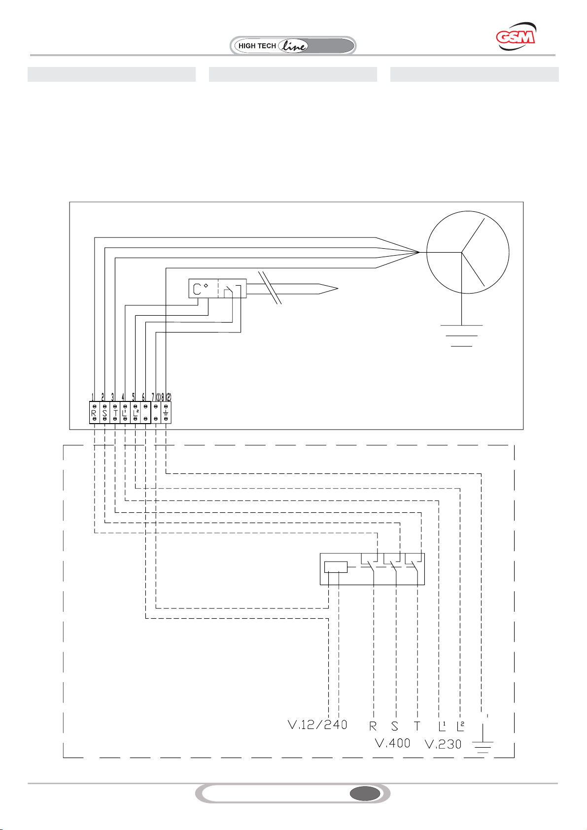
19
GSM_mod.MT02 IGBD 0.3
RX
Series
Riduttori
Industrial
8.2.2 SCHEMA ELETTRICO 8.2.2 SCHALTPLAN
8.2.2 WIRING DIAGRAM
8. COMMISSIONING 8. INBETRIEBSETZUNG8. MESSA IN SERVIZIO
Nero/Black/Schwarz
Blu (grigio)/Blue (Grey)/Blau (grau)
Marrone/Brown/Braun
Rosso Red Rot//
Nero/Black/Schwarz
Azzurro/Light blue/Hellblau
Rosso/Red/Rot
Giallo/ Yellow/GreenGelb/GrünVerde/
SCHEMA ELETTRICO
SCHALTPLAN
WIRING DIAGRAM
RFA
SCHEMA ELETTRICO
SCHALTPLAN
WIRING DIAGRAM
SCHEMA A
A
DAIAGRAM
SCHEMA
TC 1
This manual suits for next models
17
Table of contents
Other STM Industrial Equipment manuals

STM
STM NGN-8100 User manual

STM
STM ROCKETBOX 2.0 User manual

STM
STM RX Series Instruction Manual

STM
STM MINI-ROCKETBOX CANNA User manual

STM
STM MINI-ROCKETBOX PLUS+ User manual

STM
STM ROCKETBOX User manual

STM
STM ROCKETBOX Installation guide

STM
STM ATOMIC CLOSER User manual

STM
STM REVOLUTION 2.0 User manual
Popular Industrial Equipment manuals by other brands


ORELL
ORELL BLU Series Installation, operation and maintenance manual

Panasonic
Panasonic EZAEG 3W Series manual

ABB
ABB ACQ580-01 Series Quick installation and start-up guide

SCHUNK
SCHUNK KSM2 Series Installation and operating instructions

Thunderstone
Thunderstone Thunder 7000 Operation instructions

Weidmüller
Weidmüller FieldPower IoT-Box FP IoT MD01 LAN S2 manual


