manuals.online logo
Brands
  1. Home
  2. •
  3. Brands
  4. •
  5. kim lighting
  6. •
  7. Lighting Equipment
  8. •
  9. kim lighting LTV 10 Series User manual

kim lighting LTV 10 Series User manual

LIGHTVAULT®- LTV10, 20, 30 & 40 Series Installation Instructions
Revision 7/16/10 ECN 100715008 Status 18 Part No. 95567
INSTALLATION GUIDELINES:
Below grade luminaires often become ineffective or inoperable simply because they are not installed and maintained
correctly. While it is tempting to install these fixtures at or below grade, this generally turns out to be unsatisfactory
unless the installation is in a paved area. When the fixtures are installed too low, they become a collection point for dirt,
mud and encroaching ground cover. With a little preplanning and care, below-grade luminaires can be installed in a
manner that will promote easy maintenance and longevity. The following installation methods represent our best
recommendations.
Isolate and Elevate: The fundamentals of a clean, maintainable installation.
Create a Buffer Zone: When the fixtures are to be installed in
areas planted in ground cover or shrubbery, a buffer zone is
needed to prevent lens overgrowth as the plants mature.
Elevating the fixture will encourage water runoff around the
unit rather than over the top.
ADVANTAGES OF A BUFFER ZONE:
• Helps prevent lens overgrowth.
• Provides a defined edge for pruning.
• Rock fill provides drainage around fixture and helps keep the lens clean.
• Visually looks like a flush mounted installation.
Install in Concrete: Another option for installation in ground
cover, shrubbery or lawn areas is to encase the fixture in
concrete. This has some additional advantages over the
rock-fill method (above).
ADVANTAGES OF INSTALLATIONS IN CONCRETE:
• Allows higher wattage lamps because concrete
makes an excellent heat-sink.
• Helps prevent lens overgrowth.
•Allows edging without scratching fixture.
• Provides drainage around fixture and helps keep the
lens clean.
• Visually looks like a flush mounted installation.
NOTE: Always use adequate rebar surrounding the fixture
to prevent cracking of the concrete due to heat
expansion.
LTV20
LTV30
LTV720
LTV730
LTV10
LTV40
LTV710
LTV740
2” to 4”
Above
Grade
Reduced Framing
Rock /
Soil Fill
Concrete must have reinforcing
rods to prevent cracking from
fixture heat expansion.
2” to 4”
Above
Grade
Optional
Grout Mask
2” Grout Space
For Finishing
NOTE: Concrete foundation to be designed according to local soil conditions (by others).
In Paved Areas: Below-grade fixtures are not recommended
for walkover areas because high temperature lenses can burn
feet, hands, etc. However, they can be used in paved areas
that will not be used as a pathway or driveway. To make
fixture installation easier in paved areas, the optional Kim Grout
Mask may be used.
ADVANTAGES OF INSTALLATIONS IN PAVED AREAS:
•Supports fixture during concrete pour.
•Provides 2” grout space for finishing.
•Can be easily tied into reinforcing rods used for paving
and fixture shell.
•Easily adapts to any paving material.
P.O. Box 60080 •16555 East GaleAve.
City of Industry, California 91716-0080
626/968-5666 • FAX 626/330-3861
Page 2 Kim Lighting • 16555 E. Gale Ave. • P.O. Box 60080 • City of Industry, CA 91716-0080 • 626/968-5666 • FAX 626/369-2695
LIGHTVAULT®- LTV10, 20, 30 & 40 Series Installation Instructions
INSTRUCTIONS PERTAINING TO A RISK OF FIRE OR INJURY TO PERSONS
IMPORTANT SAFETY INSTRUCTIONS!
WARNING: Fixtures must be grounded in accordance with local codes or the National Electrical Code.
Failure to do so may result in serious personal injury. All electrical work should be done by a qualified
electrician.
SAFETY WARNING: Do notinstall these fixtures in submersible installations such as fountains or swim-
ming pools. Extreme caution should be taken when fixtures are used in paved areas. Lighted lamp is
HOT! High temperature lenses can burn feet, hands or objects inadvertently placed on top of fixtures. If
fixtures must be used in paved areas, locate them away from normal pedestrian traffic, and use the lowest
wattage lamp available. Do not touch hot lens, guard, or enclosure.
MAINTENANCE: To maintain light efficiency and prevent fixture overheating, lenses must be kept clean and free
of dirt, dust, leaves, trash and mineral deposits from water. For optimum performance a regularly scheduled
maintenance program should be followed. KEEP THIS SHEET FOR FUTURE REFERENCE.
CAUTION: Do not use colored lamps as they will create critical temperatures within the fixture.
To help maintain a clean, dry splice compartment, seal the conduit entries with RTV.
Do not exceed maximum wattage shown on fixture label.
Make sure all electrical supply is OFF before beginning fixture installation.
Alignment: Fixture lens frames can be installed on housings at 45° increments. Care must be taken when installing
the housing so directional lens frames can be installed at a desired orientation.
!
Tools Required: K" Socket Wrench Socket Wrench Extension RTV Sealant Torque Ratchet (inch/lbs.)
ROUGH-IN HOUSING INSTALLATION:
1. Excavate hole in desired location approximately 20" in
diameter and about 3" deeper than height of housing.
Seal all conduits entering the wiring compartment.
2. Connect housing to conduit system. Seal all conduits
entering the wiring compartment with thread sealant.
This includes both the conduit threads and the conduit
itself. (Reference instruction #6.)
BEFORE STARTING INSTALLATION READ GUIDELINES ON OPPOSITE SIDE.
Rock /
Soil Fill
Use Thread Sealant To
Prevent Water Entry
IMPORTANT: Condensation inside the fixture is a common occurrence due to the expanding and condensing of the
trapped air inside the fixture as it is cycled on and off. When the lamp is energized during the evening hours, moisture
on the inside of lens will burn off as fixture heats up. It will reappear after power is shut off and the inside air
condenses during cooling. A large majority of this moisture can be avoided by following the installation guide lines as
described in the housing installation instructions. Always relamp fixture during low humidity periods. Before closing
fixture, remove desiccant from zip lock bag and place in reflector compartment. Energize the lamp for approximately
five (5) minutes to dry air inside fixture. Install lens and lens frame as described below.
Page 3 Kim Lighting • P.O. Box 60080 • 16555 E. Gale Ave. • City of Industry, CA 91716-0080 • 626/968-5666 • FAX 626/369-2695
3. Back fill hole with sand/gravel or rock and soil for stability. Do not back fill with bark or vermicolite. Never install an
in-grade luminaire below the surrounding ground level.
4. Remove rough-in debris shield and set aside for
future use. 5. Remove splice compartment cover.
7. Pull supply conductors into splice compartment.
Make wire connections observing polarity, i.e.;
green-to-ground, white-to-common and black-to-
voltage, using water proof wire nuts. This
provides protection against circuit failure, should
water enter the junction box.
LIGHTVAULT®- LTV10, 20, 30, 40 Series Installation Instructions
6. Seal all around wires and conduit openings inside
splice compartment with RTV sealant to prevent
moisture from entering through the conduit system.
Sealant Tip: If required, the nozzle can be
extended by placing a small diameter tube or
hose on the end.
ROUGH-IN SECTION: Make certain electrical supply is OFF before starting fixture installation.
!
Rough-InHousing Installation cont'd.
Page 4 Kim Lighting • 16555 E. Gale Ave. • P.O. Box 60080 • City of Industry, CA 91716-0080 • 626/968-5666 • FAX 626/330-3861
KIM LIGHTING LIMITED WARRANTY
When installed in accordance with Kim Installation Instructions and
accepted trade practices, the following shall apply:
General Product Limited Warranty Coverage
All material and component parts used in the manufacture of Kim
Products, are warranted to be free from defects of material and/or
workmanship for a period of 1 year from date of sale, with the following
exceptions:
Auxiliary Equipment
All auxiliary equipment (such as lamps, ballasts, and transformers)
provided by and/or included in Kim Products shall carry the component
manufacturer's warranty.
Copper, Bronze and Brass Landscape Components
Copper and Bronze Landscape fixture components shall be warranted
against defects of material and/or workmanship, and failure due to
corrosion, for a period of 25 years from date of sale.
Kim Lighting's brass components are constructed from several brass
parts that are manufactured by various methods at various times. Since
brass naturally deepens in color as it ages through the normal oxidation
process, these parts may exhibit subtle differences in coloration when the
product is new. This is normal and expected. These color differences will
be eliminated shortly after installation through the normal brass oxidation
process..
Composite In-Grade Components
Composite In-Grade fixture components installed below grade, shall be
warranted against defects of material and/or workmanship, and failure
due to corrosion, for a period of 7 years from date of sale.
Aluminum Landscape Components
Aluminum Landscape fixture components not in direct contact with soil,
shall be warranted against defects of material and/or workmanship for a
period of 3 years from date of sale. Aluminum fixture components in
direct contact with soil shall be warranted from defects of material and
failure from corrosion for a period of 1 year from date of sale.
Stainless Steel Components
Stainless steel landscape components (Lens Rings) installed in the
outdoor environment shall show signs of oxidation after 5 to 6 years of
install and is dependent on the application and its environment. A proper
maintenance and cleaning program will extend the beauty of the stainless
steel.
Limit of Liability and General Conditions
Only products which are installed, used and maintained in accordance
with applicable Kim instructions, specifications and accepted trade
practices, are covered by the Kim Warranty. During the warranty period,
with proof of purchase, Kim will repair or replace with the same or similar
product, at Kim's option, without charge. Labor costs are the owner's
responsibility and are excluded from this warranty. This warranty is void
if the product is modified, tampered with, misapplied, poorly installed,
improperly maintained, or subjected to abnormal conditions.
Repair or replacement as provided under this warranty is the exclusive
remedy of the purchaser. This warranty is in lieu of all other warranties,
expressed or implied, including any implied warranty of fitness for a
particular application. Kim Lighting shall not be liable to the purchaser
for indirect or consequential damages.
Lightvault®- LTV10, 20, 30 & 40 Series Installation Instructions
How may we serve you better?
Please let us know. Visit our website at:
www.kimlighting.com
Your input is valuable to us.
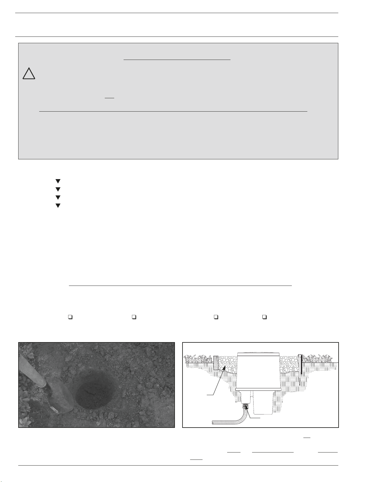
8. Replace splice compartment cover and
torque screws to 30-40 in./lbs. Place
dessicant package inside housing before
connecting quick disconnect.
9. Re-install rough-in debris shield and tighten
screws snuggly to prevent dirt and water
entry. Fixture is now ready for reflector and
lens installation. Make sure all surfaces
are completely clean before installing
covers and lens rings. Any foreign objects
trapped in the gasket areas will create
potential points of entry for ground water.
Rough-In Section cont'd.
Dessicant

This manual suits for next models

11

Other kim lighting Lighting Equipment manuals

kim lighting Bell EL 160 User manual

kim lighting

kim lighting Bell EL 160 User manual

kim lighting Bell KLV50 User manual

kim lighting

kim lighting Bell KLV50 User manual

kim lighting KLV201 User manual

kim lighting

kim lighting KLV201 User manual

kim lighting 4300 Series User manual

kim lighting

kim lighting 4300 Series User manual

kim lighting Hubbell LIGHTVAULT LTV30 User manual

kim lighting

kim lighting Hubbell LIGHTVAULT LTV30 User manual

Popular Lighting Equipment manuals by other brands

Blizzard Lighting Lo-Pro CSI user guide

Blizzard Lighting

Blizzard Lighting Lo-Pro CSI user guide

ColorKey PARTYBAR Mobile 150 user manual

ColorKey

ColorKey PARTYBAR Mobile 150 user manual

Good Earth Lighting SE1295-BRS-02LF1-G quick start guide

Good Earth Lighting

Good Earth Lighting SE1295-BRS-02LF1-G quick start guide

Vision & Control DL30x30-IR850/UDC/-a Instructions for use

Vision & Control

Vision & Control DL30x30-IR850/UDC/-a Instructions for use

ChiliTec Salao Operation manual

ChiliTec

ChiliTec Salao Operation manual

Lena Lighting LUMAX S LED installation instructions

Lena Lighting

Lena Lighting LUMAX S LED installation instructions

Chauvet Scorpion BURST GB user manual

Chauvet

Chauvet Scorpion BURST GB user manual

Blooma Shelby manual

Blooma

Blooma Shelby manual

Hayward Vistapool Instruction guide

Hayward

Hayward Vistapool Instruction guide

Vista 5275 installation instructions

Vista

Vista 5275 installation instructions

TCi VEGA Series user manual

TCi

TCi VEGA Series user manual

Ikan RB5-3PT-KIT quick start guide

Ikan

Ikan RB5-3PT-KIT quick start guide

ProLights ESABEAM user manual

ProLights

ProLights ESABEAM user manual

INNR Smart Button RC210 instructions

INNR

INNR Smart Button RC210 instructions

Home Accents Holiday TY449-1611-1 Use and care guide

Home Accents Holiday

Home Accents Holiday TY449-1611-1 Use and care guide

GP CWP15 instruction manual

GP

GP CWP15 instruction manual

PTL Mini Multi user manual

PTL

PTL Mini Multi user manual

PROEL Slimpar 5 RGBW user manual

PROEL

PROEL Slimpar 5 RGBW user manual

manuals.online logo
manuals.online logoBrands
  • About & Mission
  • Contact us
  • Privacy Policy
  • Terms and Conditions

Copyright 2025 Manuals.Online. All Rights Reserved.