Stageline BEAM-40 RGBW User manual

ELECTRONICS FOR SPECIALISTS ELECTRONICS FOR SPECIALISTS ELECTRONICS FOR SPECIALISTS ELECTRONICS FOR SPECIALISTS
BEAM-40/RGBW Bestellnummer 38.7040
BEAM-40/WS Bestellnummer 38.7050
BEDIENUNGSANLEITUNG
INSTRUCTION MANUAL
MODE D’EMPLOI
ISTRUZIONI PER L’USO
GEBRUIKSAANWIJZING
MANUAL DE INSTRUCCIONES
INSTRUKCJA OBSŁUGI
SIKKERHEDSOPLYSNINGER
SÄKERHETSFÖRESKRIFTER
TURVALLISUUDESTA
LED-Strahl-Moving-Head
LED Beam Moving Head

2
BEAM-40/…

3
Deutsch . . . . . . . . . . . . . . . . . . Seite 4
English . . . . . . . . . . . . . . . . . . . Page 8
Français . . . . . . . . . . . . . . . . . . Page 12
Italiano . . . . . . . . . . . . . . . . . . Pagina 16
Nederlands . . . . . . . . . . . . . . . Pagina 20
Español . . . . . . . . . . . . . . . . . . Página 24
Polski . . . . . . . . . . . . . . . . . . . . Strona 28
Dansk . . . . . . . . . . . . . . . . . . . . Sida 32
Svenska . . . . . . . . . . . . . . . . . . Sidan 33
Suomi . . . . . . . . . . . . . . . . . . . . Sivulta 34
ELECTRONICS FOR SPECIALISTS ELECTRONICS FOR SPECIALISTS ELECTRONICS FOR SPECIALISTS ELECTRONICS FOR SPECIALISTS

4
Deutsch
LED-Strahl-Moving-Head
Diese Anleitung richtet sich an den Bediener
mit Grundkenntnissen in der DMX-Steue-
rung. Bitte lesen Sie die Anleitung vor dem
Betrieb gründlich durch und heben Sie sie für
ein späteres Nachlesen auf. Auf der Seite 2
ist das Gerät mit allen Bedienelementen und
Anschlüssen abgebildet.
1 Einsatz- und Aufstell-
möglichkeiten
Das Gerät BEAM-40/… dient zur Effekt-
beleuchtung, z. B. auf kleinen Bühnen, auf
Partys und in Diskotheken. Als Lichtquelle ist
eine leistungsstarke 10-W-LED eingesetzt.
Das Gerät ist für die Steuerung über ein
DMX-Lichtsteuergerät ausgelegt. Es kann
aber auch allein betrieben werden, indem
ein Lichtshow-Programm automatisch oder
musikgesteuert abläuft.
Das Gerät lässt sich frei auf einer ebenen
Fläche aufstellen. Alternativ kann es kopfüber
an ein entsprechendes Trägersystem mon-
tiert werden. Dazu sind zwei Gewindelöcher
(M 6) auf der Geräteunterseite vorhanden.
2 Hinweise
für den sicheren Gebrauch
Das Gerät entspricht allen relevanten Richt-
linien der EU und ist deshalb mit gekenn-
zeichnet.
G
Verwenden Sie das Gerät nur im Innenbe-
reich. Schützen Sie es vor Tropf- und Spritz-
wasser, hoher Luftfeuchtigkeit und Hitze (zu-
lässiger Einsatztemperaturbereich 0 – 40 °C).
GDie in dem Gerät entstehende Wärme
muss durch Luftzirkulation abgegeben wer-
den. Decken Sie darum die Lüftungsöff-
nungen des Gehäuses nicht ab.
GZiehen Sie sofort den Netzstecker aus der
Steckdose,
1. wenn sichtbare Schäden am Gerät oder
am Netzkabel vorhanden sind,
2. wenn nach einem Sturz oder Ähnlichem
der Verdacht auf einen Defekt besteht,
3. wenn Funktionsstörungen auftreten.
Geben Sie das Gerät in jedem Fall zur
Reparatur in eine Fachwerkstatt.
GZiehen Sie den Netzstecker nie am Kabel
aus der Steckdose, fassen Sie immer am
Stecker an.
GVerwenden Sie für die Reinigung des Ge-
häuses nur ein trockenes, weiches Tuch,
niemals Wasser oder Chemikalien. Für die
Linse kann auch ein mildes Reinigungsmit-
tel verwendet werden.
GWird das Gerät zweckentfremdet, nicht
sicher montiert, nicht richtig angeschlos-
sen, falsch bedient oder nicht fachgerecht
repariert, kann keine Haftung für daraus
resultierende Sach- oder Personenschä-
den und keine Garantie für das Gerät über-
nommen werden.
3 Inbetriebnahme
1) Zur Stromversorgung das Gerät über die
Netzbuchse mit dem beiliegenden Netz-
kabel an eine Steckdose (230 V~/50 Hz)
anschließen.
2) Das Lichteffektgerät mit dem Schalter
POWER einschalten. Der Schwenkkopf
WARNUNG Blicken Sie nicht für längere
Zeit direkt in die Lichtquelle,
das kann zu Augenschäden
führen.
Beachten Sie, dass sehr schnelle Lichtwech-
sel bei fotosensiblen Menschen und Epilepti-
kern epileptische Anfälle auslösen können!
WARNUNG Das Gerät wird mit lebensge-
fährlicher Netzspannung ver-
sorgt. Nehmen Sie deshalb nie
selbst Eingriffe am Gerät vor
und stecken Sie nichts durch die Lüftungs-
öffnungen. Es besteht die Gefahr eines elek-
trischen Schlages.
Soll das Gerät endgültig aus dem
Betrieb genommen werden, überge-
ben Sie es zur umweltgerechten Ent-
sorgung einem örtlichen Recycling-
betrieb.

5
Deutsch
fährt in seine Ausgangsposition. Das Dis-
play zeigt den Vorgang mit (Reset) an.
Danach schaltet das Gerät in den zuletzt
gewählten Betriebsmodus. Nach kurzer
Zeit erlischt das Display. Sobald eine der
Bedientasten MENU, DOWN, UP oder
ENTER gedrückt wird, leuchtet es wieder
für kurze Zeit.
3) Nach dem Betrieb das Gerät mit dem
Schalter POWER wieder ausschalten.
4 Bedienung
Die Bedientasten MENU, UP, DOWN und
ENTER dienen zum Auswählen des Betriebs-
modus und verschiedener Funktionen
(Abb. 3). Das Display zeigt dabei den Modus
oder die Einstellung an.
Funktionen der Bedientasten
4.1 Eigenständiger Betrieb
Für den eigenständigen Betrieb kann ein
Lichtshow-Programm ablaufen.
1) Die Taste MENU so oft drücken, bis das
Display oder anzeigt.
2) Die Ablaufgeschwindigkeit mit der Taste
UP oder DOWN wählen:
= schnell
= langsam
Die Auswahl mit der Taste ENTER bestäti-
gen.
3) Soll das Programm musikgesteuert wer-
den, die Taste MENU so oft drücken, bis
angezeigt wird (Sound off). Mit der
Taste UP oder DOWN auf die Anzeige
umschalten (Sound on) und mit der
Taste ENTER bestätigen.
Taste Funktion
MENU Betriebsmodus und
Einstellmöglichkeiten anwählen
UP
DOWN Einstellung verändern
ENTER Einstellung speichern,
gewählte Funktion aktivieren
MENU
ENTER
DOWN UP
ENTER
ENTER
ENTER
ENTER
ENTER
ENTER
ENTER
DOWN UP
DOWN UP
DOWN UP
DOWN UP
DOWN UP
DOWN UP
DOWN UP
ENTER
MENU
MENU
MENU
MENU
MENU
MENU
MENU
MENU
Bedienmenü fett = Werkseinstellung
DMX-Betrieb und
Startadresse einstellen;
Adresse ab Werk: 001
Anzahl der DMX-Kanäle
BEAM-40/WS:
7 oder 9
BEAM-40/RGBW:
11 oder 13
Reset
Lichtshow-Programm
01 = schnell
02 = langsam
Musiksteuerung
oF = aus, on = ein
Schwenkkopf entgegen-
gesetzt drehen:
oF = nein, on = ja
Schwenkkopf entgegen-
gesetzt neigen:
oF = nein, on = ja
Displaydarstellung
überkopf:
oF = nein, on = ja
Zurücksetzen auf die
Werkeinstellung
oF = nein, on = ja
4.2 Betrieb mit einem DMX-Steuergerät
DMX ist die Abkürzung für Digital Multiplex
und bedeutet digitale Steuerung von mehre-
ren DMX-Geräten über eine gemeinsame
Steuerleitung. Die Funktionen der Kanäle und
die DMX-Werte sind im Kapitel 4.2.3 angege-
ben. Zur Bedienung über ein DMX-Lichtsteu-
ergerät (z. B. DMX-1440 oder DMX-510USB)
ist die folgende Anzahl von DMX-Kanälen
vorhanden:
BEAM-40/RGBW: 11 oder 13 Kanäle
BEAM-40/WS: 7 oder 9 Kanäle

6
Deutsch
4.2.1 Anschluss
Für die DMX-Verbindung sind 3-polige XLR-
Anschlüsse mit folgender Kontaktbelegung
vorhanden:
Pin 1 = Masse, 2 = DMX
-
, 3 = DMX+
Zum Anschluss sollten spezielle Kabel für die
DMX-Signalübertragung verwendet werden
(z. B. Kabel der CDMXN-Serie von „img Stage
Line“). Bei Leitungslängen ab 150 m und bei
der Steuerung von mehr als 32 Geräten über
einen DMX-Ausgang wird grundsätzlich das
Zwischenschalten eines DMX-Aufholverstär-
kers empfohlen (z. B. SR-103DMX von „img
Stage Line“)
1) Den Eingang DMX IN mit dem DMX-Aus-
gang des Lichtsteuergerätes oder eines
anderen DMX-gesteuerten Gerätes ver-
binden.
2) Den Ausgang DMX OUT mit dem DMX-
Eingang des nächsten DMX-Gerätes ver-
binden. Dessen Ausgang wieder mit dem
Eingang des nachfolgenden DMX-Gerätes
verbinden usw., bis alle DMX-gesteuerten
Geräte in einer Kette angeschlossen sind.
3) Um Störungen bei der Signalübertragung
auszuschließen, sollte bei langen Leitun-
gen bzw. bei einer Vielzahl von hintereinan-
dergeschalteten Geräten der DMX-Aus-
gang des letzten DMX-Gerätes der Kette
mit einem 120-Ω-Widerstand (> 0,3 W)
abgeschlossen werden: In die DMX-Aus-
gangsbuchse einen entsprechenden Ab-
schlussstecker (z. B. DLT-123 von „img
Stage Line“) stecken.
4.2.2 Anzahl der DMX-Kanäle
und Startadresse einstellen
Um alle am Lichtsteuergerät angeschlosse-
nen DMX-Geräte separat bedienen zu kön-
nen, muss jedes Gerät eine eigene Start-
adresse erhalten. Soll der erste DMX-Kanal
des BEAM-40 vom Lichtsteuergerät z. B.
über die DMX-Adresse 6 gesteuert werden,
am BEAM-40 die Startadresse 6 einstellen.
Die übrigen DMX-Kanäle des BEAM-40 sind
dann automatisch den darauffolgendenAdres-
sen zugeordnet. Beispiele mit verschiedenen
Startadressen:
DMX-Adressenbelegung
1BEAM-40/WS, 2BEAM-40/RGBW
1) Die Taste MENU so oft drücken, bis das
Display (für Channel) und eine Zahl an-
zeigt.
2) Die gewünschte Kanalanzahl mit der Taste
UP oder DOWN einstellen und mit der
Taste ENTER bestätigen.
3) Die Taste MENU so oft drücken, bis das
Display (für Adresse) und die aktuelle
Startadresse anzeigt.
4) Die gewünschte Adresse mit der Taste UP
oder DOWN einstellen und mit der Taste
ENTER bestätigen.
5) Damit der Moving-Head per DMX ge-
steuert werden kann, muss immer der
Menüpunkt für die Startadresse ange-
wählt bleiben. Sobald ein DMX-Steuersig-
nal empfangen wird, leuchtet ein Punkt im
Display. Die DMX-Funktionen finden Sie
im nächsten Kapitel.
Tipp: Werden zwei oder mehrere BEAM-40 syn-
chron über dieselbe Startadresse gesteuert, die
Dreh- und/oder die Neigerichtung des Schwenk-
kopfs bei einem oder mehreren Geräten entgegen-
gesetzt einstellen (Kap. 4.3). So bewegen sich die
Schwenkköpfe z. B. bei einem Gerätepaar spiegel-
bildlich.
Anzahl
der
DMX-
Kanäle
Start-
adresse
vom
BEAM-40
belegte
Adressen
nächstmögliche
Startadresse für
das nachfolgende
DMX-Gerät
7111– 7 8
66–12 13
9111– 9 10
24 24 – 32 33
11211–11 12
502 502 – 512 —
13211–13 14
60 60 – 72 73

4.2.3 DMX-Kanäle und -Funktionen
DMX-Übersicht
4.3 Zusätzliche Funktionen
Zusatzfunktionen
1) Die Funktion mit der Taste MENU über den
zugehörigen Menüpunkt anwählen (siehe
auch Abb. 3).
2) Mit der Taste UP oder DOWN auf . .
schalten (für ein Reset nicht erforderlich
und nicht möglich).
3) Zum Aktivieren der Einstellung die Taste
ENTER drücken.
5 Technische Daten
Datenprotokoll: . . . . . . . . . . DMX 512
Anzahl der DMX-Kanäle
BEAM-40/RGBW: . . . . . 11 oder 13
BEAM-40/WS: . . . . . . . . 7 oder 9
Lichtquelle
BEAM-40/RGBW: . . . . . 1 × RGBW-LED
BEAM-40/WS: . . . . . . . . 1 × LED, weiß
Leistungsaufnahme: . . . . 10 W
Abstrahlwinkel: . . . . . . . . 5°
Drehwinkel (Pan): . . . . . . . 540°
Neigungswinkel (Tilt): . . . . 270°
DMX-Anschlüsse: . . . . . . . XLR, 3-polig
Pinbelegung: . . . . . . . . . Pin 1 = Masse
Pin 2 = DMX
-
Pin 3 = DMX+
Stromversorgung: . . . . . . . 230 V~/50 Hz
Leistungsaufnahme: . . . . . max. 40 VA
Abmessungen (B × H × T): 13 × 20 × 13 cm
Gewicht: . . . . . . . . . . . . . . . 2,8 kg
Änderungen vorbehalten.
Kanalanzahl Funktion
DMX-Werte 0 – 255,
wenn nicht
anders angeben
BEAM-40/WS B.-40/RGBW
CH07 CH09 CH11 CH13
DMX-Kanal
111 1 Kopf drehen (Pan),
grob
222 2 Kopf drehen, fein
333 3 Kopf neigen (Tilt),
grob
444 4 Kopf neigen, fein
555 5 Pan-/Tilt-
Geschwindigkeit
666 6 Dimmer
777 7 Stroboskop
—— 8 8 Helligkeit Rot
—— 9 9 Helligkeit Grün
——10 10 Helligkeit Blau
——11 11 Helligkeit Weiß
—8— 12 Lichtshow-Programm
—9— 13 Reset bei DMX-Wert
150 – 200
7
Deutsch
Menüpunkt Funktion bei der
Einstellung auf . .
Schwenkkopf dreht sich
entgegengesetzt
Schwenkkopf neigt sich
entgegengesetzt
Anzeigen im Display
für eine Montage kopfüber
um 180° gedreht
Zurücksetzen auf die Werks-
einstellung (fett in Abb. 3)
Taste ENTER drücken:
Reset – Der Schwenkkopf
fährt in die Ausgangsposition
Diese Bedienungsanleitung ist urheberrechtlich für MONACOR ®INTERNATIONAL GmbH & Co. KG ge-
schützt. Eine Reproduktion für eigene kommerzielle Zwecke – auch auszugsweise – ist untersagt.

LED Beam Moving Head
These instructions are intended for users with
basic knowledge in DMX control. Please read
the instructions carefully prior to operation
and keep them for later reference. On page 2,
you will find the unit with all operating ele-
ments and connections.
1 Applications/Setting Up
The unit BEAM-40/… is used for effect light-
ing, e. g. on small stages, at parties or in
clubs. As a light source, it uses a powerful
10 W LED. The unit is designed for operation
via a DMX light controller; however, it can also
be operated independently, running an auto-
matic or music-controlled light show program.
Place the unit on a flat surface as desired.
Alternatively, install it upside down on a suit-
able lighting support system, using the two
threaded holes (M 6) on its lower side.
2 Safety Notes
The unit corresponds to all relevant directives
of the EU and is therefore marked with .
GThe unit is suitable for indoor use only. Pro-
tect it against dripping water and splash
water, high air humidity and heat (admissi-
ble ambient temperature range: 0 – 40 °C).
GThe heat produced inside the unit must be
dissipated by air circulation; therefore,
never cover the air vents of the housing.
GImmediately disconnect the mains plug
from the socket
1. if the unit or the mains cable is visibly
damaged,
2. if a defect might have occurred after the
unit was dropped or suffered a similar
accident,
3. if malfunctions occur.
In any case the unit must be repaired by
skilled personnel.
GNever pull the mains cable to disconnect
the mains plug from the socket, always
seize the plug.
GFor cleaning the housing, only use a dry,
soft cloth; never use water or chemicals.
For cleaning the lens, you may also use a
mild detergent.
GNo guarantee claims for the unit and no lia-
bility for any resulting personal damage or
material damage will be accepted if the unit
is used for other purposes than originally
intended, if it is not safely installed or not
correctly connected or operated, or if it is
not repaired in an expert way.
3 Setting into Operation
1) For power supply, connect the unit to a
mains socket (230 V~/50 Hz) via the mains
cable provided.
2) Switch on the light effect unit with the
switch POWER. The moving head will go
to its starting position. (Reset) will be
displayed. Then the unit will go to the oper-
ating mode most recently selected. The
display will extinguish after a short while.
As soon as one of the control buttons
MENU, DOWN, UP or ENTER is pressed,
the display will light up again for a short
while.
3) After operation, switch off the unit with the
switch POWER.
WARNING To prevent damage to your
eyes, never look directly into
the light source for any length of
time.
Please note that fast changes in lighting may
trigger epileptic seizures with photosensitive
persons or persons with epilepsy!
If the unit is to be put out of operation
definitively, take it to a local recycling
plant for a disposal which is not
harmful to the environment.
WARNING The unit uses dangerous mains
voltage. Leave servicing to
skilled personnel and do not
insert anything into the air
vents; inexpert handling may result in elec-
tric shock.
8
English
4 Operation
The control buttons MENU, UP, DOWN and
ENTER are used to select the operating
mode and various functions (fig. 3). The
mode or the setting will be displayed.
Functions of the control buttons
4.1 Independent operation
For independent operation, a light show pro-
gram can be activated:
1) Press the button MENU repeatedly until
or is displayed.
2) Select the program speed with the button
UP or DOWN:
= fast
= slow
Press the button ENTER to confirm.
3) For a music-controlled program, press
the button MENU repeatedly until
(Sound off) is displayed. Press the button
UP or DOWN to go to (Sound on)
and press the button ENTER to confirm.
Button Function
MENU To select the operating mode and
the setting options
UP
DOWN To change the setting
ENTER To save the setting,
to activate the function selected
9
English
4.2 Operation with a DMX controller
DMX stands for Digital Multiplexand means
digital control of multiple DMX units via a
common control line. The functions of the
channels and the DMX values can be found
in chapter 4.2.3. For control via a DMX con-
troller (e. g. DMX-1440 or DMX-510USB), the
following numbers of DMX channels are
available:
BEAM-40/RGBW: 11 or 13 channels
BEAM-40/WS: 7 or 9 channels
MENU
ENTER
DOWN UP
ENTER
ENTER
ENTER
ENTER
ENTER
ENTER
ENTER
DOWN UP
DOWN UP
DOWN UP
DOWN UP
DOWN UP
DOWN UP
DOWN UP
ENTER
MENU
MENU
MENU
MENU
MENU
MENU
MENU
MENU
Control menu bold = factory setting
Setting of DMX mode and
start address, factory-set
address: 001
Number of DMX channels
BEAM-40/WS:
7 or 9
BEAM-40/RGBW:
11 or 13
Reset
Light show program
01 = fast
02 = slow
Music control
oF = off, on
Opposite pan direction of
moving head:
oF = no, on = yes
Opposite tilt direction of
moving head:
oF = no, on = yes
Display mode for upside-
down installation:
oF = no, on = yes
Reset to factory settings
oF = no, on = yes

4.2.1 Connection
For DMX connection, 3-pole XLR connectors
with the following pin configurations are avail-
able:
Pin 1 = ground, 2 = DMX
-
, 3 = DMX+
For connection, special cables for DMX sig-
nal transmission are recommended (e. g.
cables of the CDMXN series from “img Stage
Line”). For cable lengths exceeding 150 m
and when controlling more than 32 units via a
single DMX output, it is generally recom-
mended to insert a DMX level matching
amplifier (e. g. SR-103DMX from “img Stage
Line”).
1) Connect the input DMX IN to the DMX out-
put of the light controller or of another
DMX-controlled unit.
2) Connect the output DMX OUT to the DMX
input of the second DMX-controlled unit.
Proceed in the same way to connect the
output of the second unit to the input of the
third unit etc. until all DMX-controlled units
have been connected in a chain.
3) To prevent interference in signal transmis-
sion, in case of long cables or a multitude
of units connected in series, terminate the
DMX output of the last DMX unit in the
chain with a 120 Ω resistor (> 0.3 W): Con-
nect a corresponding terminating plug
(e. g. DLT-123 from “img Stage Line”) to
the DMX output jack.
4.2.2 Setting the number of DMX channels
and the start address
For separate control of all DMX units con-
nected to the light controller, each unit must
have its own start address. Example: If the
first DMX channel of the BEAM-40 is to be
controlled by the light controller via DMX
address 6, set the start address on the
BEAM-40 to 6. All other DMX channels of the
BEAM-40 will be automatically assigned to
the subsequent addresses. Examples with
different start addresses:
DMX address assignment
1BEAM-40/WS, 2BEAM-40/RGBW
1) Press the button MENU repeatedly until
the display shows (channel) and a num-
ber.
2) Set the desired number of channels with
the button UP or DOWN and press the but-
ton ENTER to confirm.
3) Press the button MENU repeatedly until
the display shows (address) and the cur-
rent start address.
4) Set the desired address with the button UP
or DOWN and press the button ENTER to
confirm.
5) For DMX control of the moving head, the
menu item for the start address must be
selected all the time. As soon as a DMX
control signal is received, a dot will light up
on the display. The DMX functions can be
found in the next chapter.
Hint: When two or multiple BEAM-40 are synchro-
nously controlled via the same start address, set the
moving head of one or multiple units to the opposite
pan direction and/or tilt direction (chapter 4.3). Thus,
with a pair of units, the heads will move in opposite
directions (mirror-inverted).
Number
of DMX
channels
Start
address
Addresses
used by
BEAM-40
Next possible start
address for the
following DMX unit
7111– 7 8
66–12 13
9111– 9 10
24 24 – 32 33
11211–11 12
502 502 – 512 —
13211–13 14
60 60 – 72 73
10
English

4.2.3 DMX channels and functions
DMX overview
4.3 Additional functions
Additional functions
1) Go to the corresponding menu item and
select the function with the button MENU
(also see fig. 3).
2) Go to . . with the button UP or DOWN
(not necessary and not possible for reset).
3) To activate the setting, press the button
ENTER.
5 Specifications
Data protocol: . . . . . . . . . . DMX 512
Number of DMX channels
BEAM-40/RGBW: . . . . . 11 or 13
BEAM-40/WS: . . . . . . . . 7 or 9
Light source
BEAM-40/RGBW: . . . . . 1 × RGBW LED
BEAM-40/WS: . . . . . . . . 1 × LED, white
Power consumption: . . . . 10 W
Beam angle: . . . . . . . . . . 5°
Pan angle: . . . . . . . . . . . . . 540°
Tilt angle: . . . . . . . . . . . . . . 270°
DMX connections: . . . . . . . XLR, 3 poles
Pin configuration: . . . . . . Pin 1 = ground
Pin 2 = DMX
-
Pin 3 = DMX+
Power supply: . . . . . . . . . . 230 V~/50 Hz
Power consumption: . . . . . 40 VA max.
Dimensions (W × H × D): . . 13 × 20 × 13 cm
Weight: . . . . . . . . . . . . . . . . 2.8 kg
Subject to technical modification.
Number of channels Function
DMX values 0 – 255
unless otherwise
specified
BEAM-40/WS B.-40/RGBW
CH07 CH 09 CH11 CH13
DMX channel
111 1 Pan,
coarse
222 2 Pan, fine
333 3 Tilt,
coarse
444 4 Tilt, fine
555 5 Pan/tilt
speed
666 6 Dimmer
777 7 Stroboscope
—— 8 8 Brightness of red
—— 9 9 Brightness of green
——10 10 Brightness of blue
——11 11 Brightness of white
—8— 12 Light show program
—9— 13 Reset at DMX value
150 – 200
11
English
All rights reserved by MONACOR ®INTERNATIONAL GmbH & Co. KG. No part of this instruction manual
may be reproduced in any form or by any means for any commercial use.
Menu item Functions with the
setting . .
Opposite pan direction
of moving head
Opposite tilt direction
of moving head
Display mode
for upside-down installation
(rotated by 180°)
Reset to factory settings
(bold in fig. 3)
Press button ENTER:
Reset – The head will go to its
starting position.

Lyre à LED
Cette notice sʼadresse aux utilisateurs ayant
des connaissances de base dans la gestion
DMX. Veuillez lire la présente notice avec
attention avant le fonctionnement et conser-
vez-la pour pouvoir vous y reporter ultérieu-
rement. Vous trouverez sur la page 2 une
représentation de lʼappareil avec les élé-
ments et branchements.
1 Possibilités dʼutilisation
et de positionnement
La BEAM-40/… permet de créer des effets
lumineux, par exemple sur de petites scènes,
dans des soirées ou clubs. Une LED 10 W
puissante est la source lumineuse. Lʼappareil
est prévu pour une gestion via un contrôleur
DMX. Il peut également fonctionner seul et
faire défiler un programme show lumière
automatique ou géré par la musique.
Lʼappareil peut être posé librement sur
une surface plane. Il peut être monté égale-
ment sur un portique, à lʼenvers. Utilisez les
deux trous filetés (M6) sur la face inférieure
de lʼappareil.
2 Conseils dʼutilisation
et de sécurité
Lʼappareil répond à toutes les directives
nécessaires de lʼUnion européenne et porte
donc le symbole .
GLʼappareil nʼest conçu que pour une utilisa-
tion en intérieur. Protégez-le de tout type
de projections d'eau, des éclaboussures,
d'une humidité élevée de l'air et de la cha-
leur (plage de température de fonctionne-
ment autorisée : 0 – 40 °C).
GLa chaleur dégagée par lʼappareil doit être
évacuée par une circulation de lʼair : en au-
cun cas, les ouïes de ventilation du boîtier
ne doivent pas être obturées.
GDébranchez l'appareil immédiatement du
secteur lorsque :
1. des dommages visibles apparaissent sur
l'appareil ou sur le cordon secteur,
2. après une chute ou un cas similaire, vous
avez un doute sur l'état de l'appareil,
3. des dysfonctionnements apparaissent.
Dans tous les cas, les dommages doivent
être réparés par un technicien spécialisé.
GNe débranchez jamais l'appareil en tirant
sur le cordon secteur ; retirez toujours le
cordon secteur en tirant la fiche.
GPour nettoyer le boîtier, utilisez uniquement
un chiffon sec et doux, en aucun cas de
produits chimiques ou dʼeau. Pour la len-
tille, vous pouvez également utiliser un pro-
duit de nettoyage doux.
GNous déclinons toute responsabilité en cas
de dommages matériels ou corporels résul-
tants si lʼappareil est utilisé dans un but autre
que celui pour lequel il a été conçu, sʼil nʼest
pas monté dʼune manière sûre, sʼil nʼest pas
correctement branché ou utilisé ou sʼil nʼest
pas réparée par une personne habilitée, en
outre, la garantie deviendrait caduque.
3 Fonctionnement
1) Pour lʼalimentation, reliez lʼappareil via la
prise secteur à une prise 230 V~/50 Hz
avec le cordon secteur livré.
CARTONS ET EMBALLAGE
PAPIER À TRIER
AVERTISSEMENT Ne regardez jamais directe-
ment la source lumineuse,
cela pourrait causer des
troubles de la vision.
N'oubliez pas que des changements très
rapides de lumière peuvent déclencher des
crises d'épilepsie chez les personnes photo-
sensibles et épileptiques.
Lorsque lʼappareil est définitivement
retiré du service, vous devez le dé-
poser dans une usine de recyclage
adaptée pour contribuer à son élimi-
nation non polluante.
AVERTISSEMENT Lʼappareil est alimenté par
une tension dangereuse.
Ne touchez jamais l'inté-
rieur de l'appareil et n'insé-
rez rien dans les ouïes de ventilation !
Risque de décharge électrique.
12
Français

2) Allumez lʼappareil avec lʼinterrupteur
POWER. La tête se met sur sa position de
départ. Lʼaffichage indique le processus
avec (Reset). Ensuite lʼappareil va au
dernier mode de fonctionnement sélec-
tionné. Peu de temps après, lʼaffichage
sʼéteint. Dès quʼune touche de commande
MENU, DOWN, UP ou ENTER est activée,
il se rallume brièvement.
3) Après le fonctionnement, éteignez lʼappa-
reil avec lʼinterrupteur POWER.
4 Utilisation
Les touches MENU, UP, DOWN et ENTER
permettent de sélectionner le mode de fonc-
tionnement et différentes fonctions (schéma 3).
Lʼaffichage indique le réglage ou le mode.
Fonctions des touches de commande
4.1 Fonctionnement autonome
Pour un fonctionnement autonome, un pro-
gramme show lumière peut être activé :
1) Appuyez sur la touche MENU de manière
répétée jusquʼà ce que lʼaffichage indique
ou .
2) Sélectionnez la vitesse de défilement avec
la touche UP ou DOWN :
= rapide
= lent
Confirmez la sélection avec la touche
ENTER.
3) Si le programme doit être géré par la
musique, appuyez sur la touche MENU de
manière répétée jusquʼà ce que
(Sound off) soit affiché. Avec la touche UP
ou DOWN, commutez sur lʼaffichage
(Sound on) et confirmez avec la touche
ENTER.
Touche Fonction
MENU sélection du mode de fonctionnement
et des possibilités de réglage
UP
DOWN modification du réglage
ENTER mémorisation du réglage,
activation de la fonction sélectionnée
13
Français
4.2 Fonctionnement avec
un contrôleur DMX
DMX est l'abréviation de Digital Multiplexet
signifie une commande digitale de plusieurs
appareils DMX via un câble commun de com-
mande. Vous trouverez les fonctions des
canaux et les valeurs DMX dans le chapi-
tre 4.2.3. Pour une gestion via un contrôleur
DMX (p. ex. DMX-1440 ou DMX-510USB), le
nombre de canaux DMX est le suivant :
BEAM-40/RGBW 11 ou 13 canaux
BEAM-40/WS : 7 ou 9 canaux
MENU
ENTER
DOWN UP
ENTER
ENTER
ENTER
ENTER
ENTER
ENTER
ENTER
DOWN UP
DOWN UP
DOWN UP
DOWN UP
DOWN UP
DOWN UP
DOWN UP
ENTER
MENU
MENU
MENU
MENU
MENU
MENU
MENU
MENU
Menu de commande en gras : réglages d'usine
Fonctionnement DMX et
réglage de lʼadresse de
démarrage ; adresse ré-
glée en usine : 001
Nombre de canaux DMX
BEAM-40/WS:
7 ou 9
BEAM-40/RGBW:
11 ou 13
Reset
Programme show lumière
01 = rapide
02 = lent
Gestion par la musique
oF = désactivée,
on = activée
Tête : rotation inversée
oF = désactivée,
on = activée
Tête : inclinaison inversée
oF = désactivée,
on = activée
Visualisation affichage
inversée :
oF = désactivée,
on = activée
Réinitialisation sur les
réglages dʼusine
oF = désactivée,
on = activée

4.2.1 Branchement
Pour la connexion DMX, des branchements
XLR 3 pôles avec la configuration de contact
suivante sont prévus :
Pin 1 = masse, 2 = DMX
-
, 3 = DMX+
Pour le branchement, il est recommandé
d'utiliser des câbles spécifiques pour la trans-
mission de signaux DMX (par exemple
câbles de la série CDMXN de “img Stage
Line”). Pour des longueurs de liaison à partir
de 150 m et pour une gestion de plus de 32
appareils via une seule sortie DMX, il est
recommandé d'insérer un amplificateur DMX
de signal (par exemple SR-103DMX de “img
Stage Line”).
1) Reliez lʼentrée DMX IN à la sortie DMX du
contrôleur ou dʼun autre appareil géré par
DMX.
2) Reliez la sortie DMX OUT à lʼentrée DMX
du prochain appareil DMX. Reliez sa sor-
tie à lʼentrée de lʼappareil DMX suivant et
ainsi de suite de manière à ce que tous les
appareils gérés par DMX forment une
chaîne.
3) Pour éviter les perturbations lors de la
transmission du signal, il convient, pour de
longs câbles ou pour une multitude dʼap-
pareils branchés les uns derrière les
autres, de terminer la sortie DMX du der-
nier appareil DMX de la chaîne avec une
résistance 120 Ω (> 0,3 W) : mettez un
bouchon (par exemple DLT-123 de “img
Stage Line“) dans la prise de sortie DMX.
4.2.2 Réglage du nombre de canaux DMX
et de lʼadresse de démarrage
Pour pourvoir utiliser séparément tous les
appareils DMX reliés au contrôleur, il faut que
chaque appareil aie une adresse de démar-
rage propre. Si le premier canal DMX de la
BEAM-40 doit être géré par le contrôleur, par
exemple, via lʼadresse DMX 6, réglez sur la
BEAM-40, lʼadresse de démarrage 6. Les
autres canaux DMX de la BEAM-40 sont
automatiquement attribués aux adresses sui-
vantes. Exemples avec différentes adresses
de démarrage :
Configuration des adresses DMX
1BEAM-40/WS, 2BEAM-40/RGBW
1) Appuyez sur la touche MENU de manière
répétée jusquʼà ce que lʼaffichage indique
(pour Channel) et un chiffre.
2) Réglez le nombre souhaité de canaux
avec la touche UP ou DOWN et confirmez
avec ENTER.
3) Appuyez sur la touche MENU de manière
répétée jusquʼà ce que sur lʼaffichage, la
lettre (pour adresse) et lʼadresse de
démarrage actuelle soient visibles.
4) Réglez l'adresse souhaitée avec la touche
UP ou DOWN et confirmez avec la touche
ENTER.
5) Pour que la lyre puisse être gérée par
DMX, il faut que le point de menu pour
adresse de démarrage soit toujours sélec-
tionné. Dès quʼun signal de commande
DMX est reçu, un point est visible sur lʼaf-
fichage. Vous trouverez les fonctions DMX
dans le chapitre suivant.
Conseil : Si deux ou plusieurs BEAM-40 sont gérées
de manière synchrone via la même adresse de
démarrage, réglez le sens de rotation et dʼinclinaison
de la tête pour un ou plusieurs appareils à lʼinverse
(chapitre 4.3). Les têtes se déplacent alors, par
exemple pour une paire dʼappareils, dans les sens
opposés.
Nombre
de
canaux
DMX
Adresse
de
démar-
rage
Adresses
utilisées par
la BEAM-40
Adresse de démar-
rage suivante pos-
sible pour lʼappareil
DMX suivant
7111– 7 8
66–12 13
9111– 9 10
24 24 – 32 33
11211–11 12
502 502 – 512 —
13211–13 14
60 60 – 72 73
14
Français

4.2.3 Canaux DMX et fonctions DMX
Aperçu DMX
4.3 Fonctions supplémentaires
Fonctions supplémentaires
1) Sélectionnez la fonction avec la touche
MENU via le point de menu correspondant
(voir également schéma 3).
2) Avec la touche UP ou DOWN, commutez
sur . . (pas nécessaire et impossible
pour réinitialisation).
3) Pour activer le réglage, appuyez sur la
touche ENTER.
5 Caractéristiques techniques
Protocole données : . . . . . . DMX 512
Nombre de canaux DMX
BEAM-40/RGBW : . . . . . 11 ou 13
BEAM-40/WS : . . . . . . . . 7 ou 9
Source lumineuse
BEAM-40/RGBW : . . . . . 1 × LED RGBW
BEAM-40/WS : . . . . . . . . 1 × LED, blanc
Consommation : . . . . . . . 10 W
Angle de rayonnement : . 5°
Angle rotation (Pan) : . . . . . 540°
Angle inclinaison (Tilt) : . . . 270°
Branchements DMX : . . . . . XLR, 3 pôles
Configuration : . . . . . . . . Pin 1 = Masse
Pin 2 = DMX
-
Pin 3 = DMX+
Alimentation : . . . . . . . . . . . 230 V~/50 Hz
Consommation : . . . . . . . . . 40 VA max.
Dimensions (L × H × P) : . . 13 × 20 × 13 cm
Poids : . . . . . . . . . . . . . . . . 2,8 kg
Tout droit de modification réservé.
Nombre de canaux Fonction
valeurs DMX 0 – 255
si rien dʼautre
nʼest indiqué
BEAM-40/WS B.-40/RGBW
CH07 CH 09 CH11 CH13
Canal DMX
111 1 rotation tête (Pan),
grossier
222 2 rotation tête, fin
333 3 inclinaison tête (Tilt),
grossier
444 4 inclinaison tête, fin
555 5 vitesse
Pan/Tilt
666 6 dimmer
777 7 stroboscope
—— 8 8 luminosité rouge
—— 9 9 luminosité vert
——10 10 luminosité bleu
——11 11 luminosité blanc
—8— 12 programme show
lumière
—9— 13 reset pour valeur DMX
150 – 200
15
Français
Notice dʼutilisation protégée par le copyright de MONACOR ®INTERNATIONAL GmbH & Co. KG. Toute
reproduction même partielle à des fins commerciales est interdite.
Point menu Fonction avec
réglage sur . .
la tête tourne en sens
inverse
la tête sʼincline en sens
inverse
indication sur lʼaffichage
inversée de 180° pour
un montage inversé
réinitialisation sur
les réglages dʼusine
(en gras sur le schéma 3)
Appuyez sur la touche ENTER :
Reset – la tête revient
à la position de départ

LED Beam Moving Head
Queste istruzioni sono rivolte allʼutente con
conoscenze base dei comandi DMX. Vi pre-
ghiamo di leggerle attentamente prima della
messa in funzione e di conservarle per un
uso futuro. A pagina 2 vedrete l'apparecchio
con tutti gli elementi di comando e collega-
menti.
1 Possibilità d'impiego
e di collocazione
L'apparecchio BEAM-40/… serve per l'illumi-
nazione a effetto, su palcoscenici piccoli,
durante party e in discoteche. Come fonte di
luce è inserito un LED potente di 10 W. L'ap-
parecchio è previsto per il comando tramite
unʼunità DMX di comando luce. Tuttavia, può
essere usato anche in modo autonomo, con
un programma di light-show che si svolge
automaticamente o comandato dalla musica.
Lʼapparecchio può essere collocato libe-
ramente su un piano pari. In alternativa può
essere montato a rovescio su una traversa.
Per tale caso, sul lato inferiore dell'apparec-
chio si trovano due fori filettati (M 6).
2 Avvertenze per lʼuso sicuro
Lʼapparecchio è conforme a tutte le direttive
rilevanti dellʼUE e pertanto porta la sigla .
GUsare lʼapparecchio solo allʼinterno di locali
e proteggerlo dall'acqua gocciolante e dagli
spruzzi d'acqua, da alta umidità dell'aria e
dal calore (temperatura dʼimpiego am-
messa fra 0 e 40 °C).
GDevʼessere garantita la libera circolazione
dellʼaria per dissipare il calore che viene
prodotto allʼinterno dell'apparecchio. Non
coprire in nessun modo le fessure dʼaera-
zione del contenitore.
GStaccare subito la spina dalla presa di rete
se:
1. lʼapparecchio o il cavo rete presentano
dei danni visibili;
2. dopo una caduta o dopo eventi simili
sussiste il sospetto di un difetto;
3. lʼapparecchio non funziona corretta-
mente.
Per la riparazione rivolgersi sempre ad
unʼofficina competente.
GStaccare il cavo rete afferrando la spina,
senza tirare il cavo.
GPer la pulizia del contenitore usare solo un
panno morbido, asciutto; non impiegare in
nessun caso acqua o prodotti chimici. Per
la lente si può usare anche un detergente
delicato.
GNel caso dʼuso improprio, di montaggio non
sicuro, di collegamenti sbagliati, dʼimpiego
scorretto o di riparazione non a regola
dʼarte dellʼapparecchio, non si assume nes-
suna responsabilità per eventuali danni
consequenziali a persone o a cose e non si
assume nessuna garanzia per lʼapparec-
chio.
3 Messa in funzione
1) Per lʼalimentazione, collegare lʼapparec-
chio tramite la presa per alimentazione
con una presa di rete (230 V~/50 Hz)
usando il cavo in dotazione.
2) Con l'interruttore POWER, accendere
l'unità per effetti di luce. La testa mobile si
porta nella sua posizione di partenza. Il
display visualizza la procedura con
AVVERTIMENTO Non guardare a lungo diret-
tamente nella fonte di luce
per escludere possibili danni
agli occhi.
Tenete presente che i veloci cambi di luce
possono provocare attacchi d'epilessia
presso persone fotosensibili o epilettici!
Se si desidera eliminare lʼapparec-
chio definitivamente, consegnarlo
per lo smaltimento ad un'istituzione
locale per il riciclaggio.
AVVERTIMENTO Lʼapparecchio è alimentato
con pericolosa tensione di
rete. Non intervenire mai
personalmente al suo interno
e non inserire niente nelle fessure di aera-
zione! Esiste il pericolo di una scarica
elettrica.
16
Italiano

(Reset). Dopodiché, l'apparecchio passa
nel modo scelto per ultimo. Dopo poco
tempo, il display si spegne. Non appena si
preme uno dei tasti MENU, DOWN, UP o
ENTER il display si riaccende per poco
tempo.
3) Dopo l'uso spegnere l'apparecchio con
l'interruttore POWER.
4 Funzionamento
I tasti funzione MENU, UP, DOWN e ENTER
servono per scegliere il modo di funziona-
mento e varie funzioni (fig. 3). Il display indica
il modo oppure l'impostazione.
Funzioni dei tasti di funzione
4.1 Funzionamento autonomo
Per il funzionamento autonomo si può svol-
gere un programma di light-show.
1) Premere tante volte il tasto MENU finché il
display visualizza o .
2) Con il tasto UP o DOWN scegliere la velo-
cità di svolgimento:
= veloce
= lento
Confermare la scelta con il tasto ENTER.
3) Se il programma deve essere comandato
dalla musica, premere tante volte il tasto
MENU finché si vede (Sound off).
Con il tasto UP o DOWN passare all'indi-
cazione (Sound on) e confermare
con il tasto ENTER.
Tasto Funzione
MENU Scegliere il modo di funzionamento e
le possibilità dʻimpostazione
UP
DOWN Modificare l'impostazione
ENTER Salvare lʼimpostazione e
attivare la funzione scelta
17
Italiano
4.2 Funzionamento con un'unità
di comando DMX
DMX è l'abbreviazione per Digital Multiplexe
significa comando digitale di più apparecchi
DMX tramite una sola linea di comando. Le
funzioni dei canali e i valori DMX sono indicati
nel capitolo 4.2.3. Per il comando tramite
unʼunità DMX di comando luce (p. es. DMX-
1440 o DMX-510USB) è presente il numero
seguente dei canali DMX:
BEAM-40/RGBW: 11 o 13 canali
BEAM-40/WS: 7 o 9 canali
MENU
ENTER
DOWN UP
ENTER
ENTER
ENTER
ENTER
ENTER
ENTER
ENTER
DOWN UP
DOWN UP
DOWN UP
DOWN UP
DOWN UP
DOWN UP
DOWN UP
ENTER
MENU
MENU
MENU
MENU
MENU
MENU
MENU
MENU
Menu dei comandi grassetto = Impostazioni
della fabbrica
Impostare funzionamento
DMX e indirizzo di start;
Indirizzo dalla fabbrica: 001
Numero dei canali DMX
BEAM-40/WS:
7 o 9
BEAM-40/RGBW:
11 o 13
Reset
Programma light-show
01 = veloce
02 = lento
Comando tramite la musica
oF = spento, on = attivato
Muovere la testa mobile in
senso opposto:
oF = no, on = si
Inclinare la testa mobile in
senso opposto:
oF = no, on = si
Rappresentazione sul
display a rovescio:
oF = no, on = si
Reset alle impostazioni
della fabbrica
oF = no, on = si

4.2.1 Collegamento
Per il collegamento DMX, sono disponibili dei
contatti XLR a 3 poli con la seguente piedina-
tura:
pin 1 = massa, 2 = DMX
-
, 3 = DMX+
Per il collegamento si dovrebbero usare cavi
speciali per la trasmissione di segnali DMX
(p. es. cavi della serie CDMXN di “img Stage
Line”). Nel caso di lunghezze oltre i 150 m e
di comando di più di 32 apparecchi tramite
una sola uscita DMX, si consiglia per princi-
pio lʼimpiego di un amplificatore DMX (p. es.
SR-103DMX di “img Stage Line”).
1) Collegare l'ingresso DMX IN con l'uscita
DMX dell'unità di comando luce o di un
altro apparecchio con comando DMX.
2) Collegare l'uscita DMX OUT con l'ingresso
DMX dell'apparecchio successivo e la sua
uscita con l'ingresso dell'apparecchio DMX
seguente ecc., finché tutti gli apparecchi
con comando DMX sono collegati for-
mando una catena.
3) Per escludere interferenze durante la tra-
smissione dei segnali, nel caso di linee
lunghe o di un gran numero di apparecchi
collegati in serie, l'uscita DMX dell'ultimo
apparecchio DMX della catena dovrebbe
essere terminata con una resistenza di
120 Ω (> 0,3 W): Inserire nella presa
d'uscita DMX un terminatore (p. es. DLT-
123 di “img Stage Line”).
4.2.2 Impostare il numero dei canali DMX
e lʼindirizzo di start
Per poter comandare separatamente tutti gli
apparecchi DMX collegati con l'unità per
comando luce, ogni apparecchio deve avere
il suo indirizzo di start. Se il primo canale
DMX del BEAM-40 deve essere comandato
dall'unità per comando luce p. es. tramite
l'indirizzo DMX 6, impostare sul BEAM-40
l'indirizzo di start 6. I rimanenti canali DMX
del BEAM-40 saranno assegnati automatica-
mente agli indirizzi successivi. Esempi con
vari indirizzi di start:
Indirizzi di start DMX del
1BEAM-40/WS, 2BEAM-40/RGBW
1) Premere il tasto MENU tante volte finché il
display visualizza (per Channel) e un
numero.
2) Con il tasto UP o DOWN impostare il
numero desiderato per il canale e confer-
mare con il tasto ENTER.
3) Premere il tasto MENU tante volte finché
sul display si vede (per address = Indi-
rizzo) e l'indirizzo di start attuale.
4) Impostare l'indirizzo desiderato con il tasto
UP o DOWN e confermare con il tasto
ENTER.
5) Affinché la moving head possa essere
comandata tramite DMX, deve sempre
essere scelta la voce per l'indirizzo di
start. Non appena si riceve un segnale di
comando DMX, sul display si accende un
punto. Le funzioni DMX si trovano nel capi-
tolo successivo.
Un consiglio: Se due o più BEAM-40 sono coman-
dati in sincronia tramite il medesimo indirizzo di start,
impostare in modo opposto il senso di rotazione e/o
d'inclinazione della testa mobile per uno o più appa-
recchi (Cap. 4.3). In questo modo, le teste mobili si
muovono, p. es. con una coppia di apparecchi, in
senso rispecchiato.
Numero
dei
canali
DMX
Indirizzo
di start
Indirizzi
occupati dal
BEAM-40
Prossimo indirizzo
di start possibile
per l'apparecchio
DMX successivo
7111– 7 8
66–12 13
9111– 9 10
24 24 – 32 33
11211–11 12
502 502 – 512 —
13211–13 14
60 60 – 72 73
18
Italiano

4.2.3 Canali e funzioni DMX
Panorama DMX
4.3 Funzioni supplementari
Funzioni supplementari
1) Con il tasto MENU, scegliere la funzione
tramite la relativa voce del menu (vedi
anche fig. 3).
2) Con il tasto UP o DOWN passare a . .
(non necessario e non possibile per il
reset).
3) Per attivare l'impostazione premere il tasto
ENTER.
5 Dati tecnici
Protocollo dati: . . . . . . . . . . DMX 512
Numero dei canali DMX
BEAM-40/RGBW: . . . . . 11 o 13
BEAM-40/WS: . . . . . . . . 7 o 9
Fonte di luce
BEAM-40/RGBW: . . . . . 1 × LED RGBW
BEAM-40/WS: . . . . . . . . 1 × LED, bianco
Potenza assorbita: . . . . . 10 W
Angolo d'emissione: . . . . 5°
Angolo di rotazione (Pan): . 540°
Angolo d'inclinazione (Tilt): 270°
Contatti DMX: . . . . . . . . . . XLR, 3 poli
Piedinatura: . . . . . . . . . . pin 1 = massa
pin 2 = DMX
-
pin 3 = DMX+
Alimentazione: . . . . . . . . . . 230 V~/50 Hz
Potenza assorbita: . . . . . . . max. 40 VA
Dimensioni (l × h × p): . . . . 13 × 20 × 13 cm
Peso: . . . . . . . . . . . . . . . . . 2,8 kg
Con riserva di modifiche tecniche.
Numero canali Funzione
Valori DMX 0 – 255,
se non indicato
diversamente
BEAM-40/WS B.-40/RGBW
CH07 CH 09 CH11 CH13
Canale DMX
111 1 roteare la testa (Pan),
grossolano
222 2 roteare la testa, fine
333 3 inclinare la testa (Tilt),
grossolano
444 4 inclinare la testa, fino
555 5 velocità
Pan/Tilt
666 6 dimmer
777 7 stroboscopio
—— 8 8 luminosità rosso
—— 9 9 luminosità verde
——10 10 luminosità blu
——11 11 luminosità bianco
—8— 12 programma light-show
—9— 13 reset con valore DMX
150 – 200
19
Italiano
La MONACOR ®INTERNATIONAL GmbH & Co. KG si riserva ogni diritto di elaborazione in qualsiasi forma
delle presenti istruzioni per lʼuso. La riproduzione – anche parziale – per propri scopi commerciali è vietata.
Voce del menu Funzione con
impostazione a . .
la testa mobile rotea
in senso opposto
la testa mobile s'inclina
in senso opposto
indicazioni sul display
per il montaggio a rovescio,
girate di 180°
reset alle impostazioni della fab-
brica (grassetto in fig. 3)
premere il tasto ENTER:
Reset – La testa mobile si porta
nella sua posizione di partenza

Moving Head met ledstraal
Deze handleiding is bedoeld voor de gebrui-
ker met basiskennis van de DMX-besturing.
Lees de handleiding grondig door, alvorens
het apparaat in gebruik te nemen, en bewaar
ze voor latere raadpleging. Op pagina 2 wordt
het apparaat afgebeeld met alle bedienings-
elementen en aansluitingen.
1 Gebruiks- en
installatiemogelijkheden
Het apparaat BEAM-40/… wordt gebruikt
voor effectverlichting, bv. op kleine podia, op
feestjes en in discotheken. Als lichtbron wordt
een krachtige led van 10 W gebruikt. Het
apparaat is ontworpen voor het besturen via
een DMX-lichtregelaar. Het kan echter ook
alleen worden gebruikt, door een lichtshow-
programma automatisch of muziekgestuurd
te laten aflopen.
Het apparaat kan vrij op een vlakke
ondergrond worden opgesteld. Het kan ook
ondersteboven aan een hiervoor bedoeld
draagsysteem worden gemonteerd. Hiervoor
zijn twee draadgaten (M 6) aan de onderzijde
van het apparaat beschikbaar.
2 Veiligheidsvoorschriften
Het apparaat is in overeenstemming met alle
relevante EU-Richtlijnen en is daarom geken-
merkt met .
G
Het apparaat is uitsluitend geschikt voor ge-
bruik binnenshuis. Vermijd druip- en spat-
water, uitzonderlijk warme plaatsen en plaat-
sen met een hoge vochtigheid (toegestaan
omgevingstemperatuurbereik: 0 – 40 °C)
.
GDe warmte die in het apparaat ontstaat,
moet door ventilatie worden afgevoerd.
Dek daarom de ventilatieopeningen van de
behuizing niet af.
GTrek onmiddellijk de netstekker uit het stop-
contact,
1. wanneer het toestel of het netsnoer
zichtbaar beschadigd is,
2. wanneer er een defect zou kunnen
optreden nadat het apparaat bijvoor-
beeld is gevallen,
3. wanneer het apparaat slecht functio-
neert.
Het apparaat moet in elk geval worden her-
steld door een gekwalificeerd vakman.
GTrek de stekker nooit met het snoer uit het
stopcontact, maar met de stekker zelf.
GVerwijder het stof van de behuizing met een
droge, zachte doek. Gebruik zeker geen
water of chemicaliën. Voor de lens kunt u
ook een mild reinigingsmiddel gebruiken.
GIn geval van ongeoorloofd of verkeerd ge-
bruik, onveilige montage, verkeerde aan-
sluiting, foutieve bediening of van herstel-
ling door een niet-gekwalificeerd persoon
vervalt de garantie en de verantwoordelijk-
heid voor hieruit resulterende materiële of
lichamelijke schade.
3 Ingebruikname
1) Voor de voedingsspanning verbindt u de
netaansluiting van het apparaat via het bij-
geleverde netsnoer met een stopcontact
(230 V~/50 Hz).
2) Schakel het lichteffectenapparaat in met
de schakelaar POWER. De zwenkkop be-
OPGELET Kijk niet rechtstreeks in de licht-
bron gedurende lange tijd,
omdat dit de ogen kan bescha-
digen.
Weet dat stroboscoopeffecten en zeer
snelle lichtwisselingen bij fotosensibele
mensen en epileptici epileptische aanvallen
kunnen veroorzaken!
Wanneer het apparaat definitief uit
bedrijf wordt genomen, bezorg het
dan voor milieuvriendelijke verwer-
king aan een plaatselijk recyclage-
bedrijf.
WAARSCHUWING De netspanning van de
apparaat is levensgevaar-
lijk. Open het apparaat niet,
en zorg dat u niets in de
ventilatieopeningen steekt. U loopt immers
het risico van een elektrische schok.
20
Nederlands
This manual suits for next models
1
Table of contents
Languages:
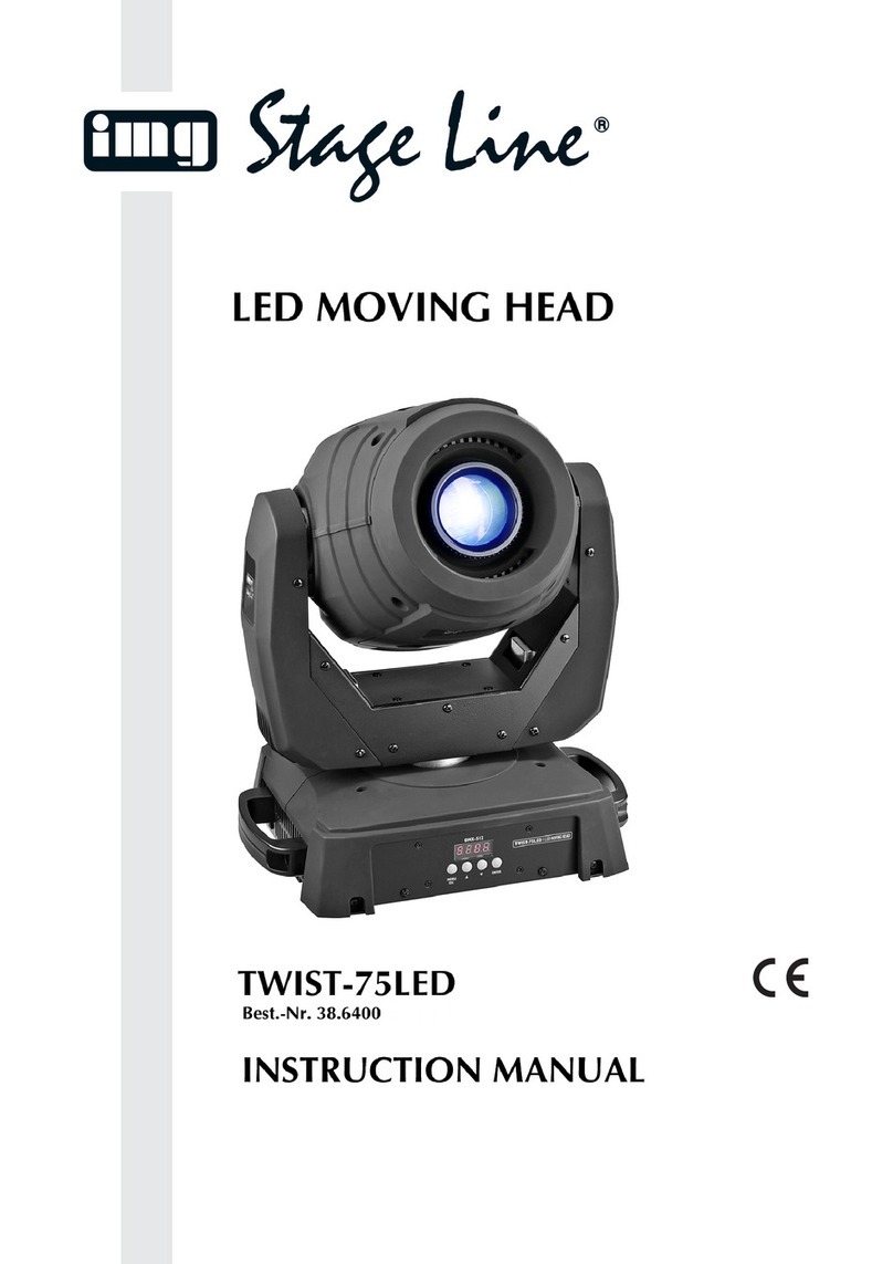
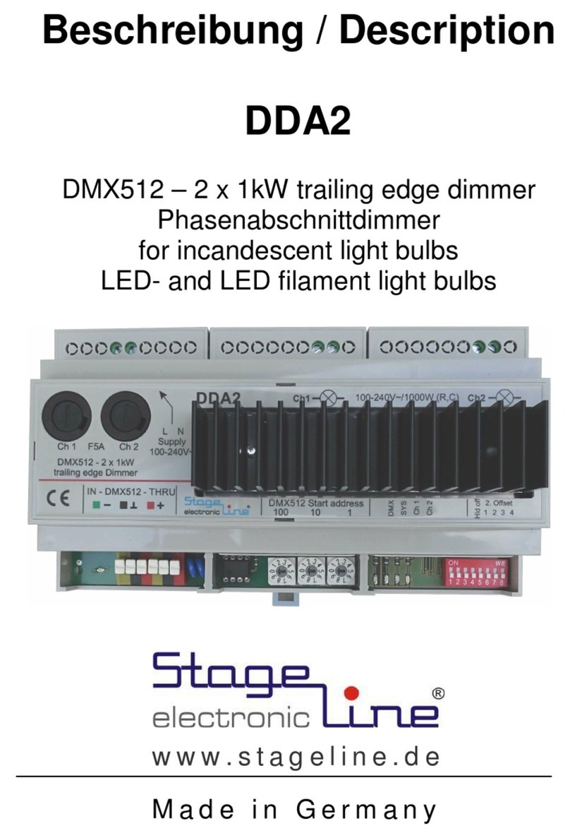
Other Stageline Lighting Equipment manuals

Stageline
Stageline INCREDIBLE User manual

Stageline
Stageline Galactic 250-RVP User manual

Stageline
Stageline LSE-2LRG User manual

Stageline
Stageline LSX-650SRGB User manual

Stageline
Stageline TWIST-75LED User manual

Stageline
Stageline LSX-049SG User manual

Stageline
Stageline DDA2 User manual

Stageline
Stageline SCAN-150 User manual