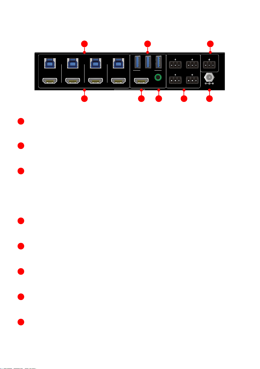
Kindermann 5778 000 150 Service manual

01.2021
GB
D
Montage- und Bedienungsanleitung
Mounting and operating instructions
HDMI Switch 41 4K60 KVM
Art.-Nr. 5778000150
Ref. No. 5778000150

2
D
Inhaltsverzeichnis
1. Vorwort ...........................................................................................................................................................3
2. Sicherheitshinweise und Vorsichtsmaßnahmen..................................................................................3
3. Produktbeschreibung..................................................................................................................................
3.1. Eigenschaften ....................................................................................................................................
3.2. Lieferumfang .....................................................................................................................................
4. Gerätebeschreibung............................................................................................................................. -
4.1. Vorderseite .........................................................................................................................................
4.2. Rückseite.............................................................................................................................................
Anschlussschema.........................................................................................................................................
Bedienung ......................................................................................................................................................
ManuellesUmschalten ....................................................................................................................
AutomatischesUmschalten...........................................................................................................
Kontakteingänge.........................................................................................................................................
RSSteuerung ................................................................................................................................-
RSBefehle ...................................................................................................................................
Gerätesteuerung .....................................................................................................................
Quellenumschaltung..........................................................................................................
AudioEinstellungen...........................................................................................................
EDIDManagement.............................................................................................................
HDCPEinstellungen...........................................................................................................
EinstellungderDatenrate .................................................................................................
SchwarzerBildschirm........................................................................................................
FirmwareUpgrade....................................................................................................................................
TechnischeDaten ...................................................................................................................................
Fehlerbehebung .....................................................................................................................................
CE-Konformitätserklärung ..................................................................................................................

3
1. Vorwort
Bevor Sie das Produkt verwenden, lesen Sie diese Bedienungsanleitung sorgfältig durch. Die in diesem
Handbuch gezeigten Bilder dienen nur als Referenz und können sich vom realen Produkt unterscheiden.
Wenden Sie sich an den örtlichen Händler, um Unterstützung bei der Wartung zu erhalten.
Im ständigen Bemühen, das Produkt zu verbessern, behalten wir uns das Recht vor, Funktionen oder
Parameter ohne vorherige Ankündigung oder Verpflichtung zu ändern. Die neuesten Informationen
erhalten Sie von Ihrem Kindermann Fachhändler.
2. Sicherheitshinweise und Vorsichtsmaßnahmen
• Lesen Sie die Bedienungsanleitung sorgfältig durch und bewahren Sie diese auf.
• Packen Sie das Gerät vorsichtig aus und heben Sie die Originalverpackung und das Verpackungs-
material für einen eventuellen späteren Versand auf.
• Befolgen Sie die grundlegenden Sicherheitsvorkehrungen, um die Gefahr von Bränden,
Stromschlägen und Verletzungen von Personen zu verringern.
• Önen oder modifizieren Sie niemals das Gerät. Dies kann zu Stromschlägen oder Verbrennungen
führen.
• Das Produkt darf nur mit Sicherheitskleinspannung und mit dem mitgelieferten Netzteil betrieben
werden.
• Die Verwendung von Verbrauchsmaterialien oder Teilen, die nicht den Produktspezifikationen
entsprechen, kann zu Beschädigung oder Fehlfunktion führen.
• Wenden Sie sich bei allen Wartungsarbeiten an qualifiziertes Servicepersonal.
• Das System darf nur in trockener Umgebung gelagert und eingesetzt werden.
• Stellen Sie das Gerät an einem gut belüfteten Ort auf, um Schäden durch Überhitzung zu vermeiden.
• Verwenden Sie zum Reinigen dieses Geräts keine Flüssigkeits- oder Aerosolreiniger.
Ziehen Sie vor dem Reinigen immer den Netzstecker aus der Steckdose.
• Ziehen Sie den Netzstecker, wenn Sie das Gerät längere Zeit nicht benutzen.
• Vergewissern Sie sich vor der Installation, dass alle Komponenten und Zubehörteile enthalten sind.
• Alle Netzschalter, Stecker, Steckdosen und Netzkabel müssen isoliert und sicher sein.
• Alle Kabel sollten vor dem Einschalten angeschlossen werden.
• Hinweise zur Entsorgung von Altgeräten: Das Gerät darf nicht mit dem Hausmüll entsorgt werden,
sondern ist über den Handelsweg zurückzugeben.

4
3. Produktbeschreibung
Danke, dass Sie sich für den HDMI Switch 41 4K60 KVM entschieden haben. Der Umschalter verfügt über
vier HDMI Eingänge und einen HDMI Ausgang. Er unterstützt HDMI Signale bis zu 4Kx2K@60Hz 4:4:4
HDR 10 und Dolby Vision Audioqualität. Zusätzlich sind vier USB 3.0 Typ B Anschlüsse (Host) und drei
USB 3.0 Typ A Schnittstellen (Device) z. B. für KVM Anwendungen vorhanden, die dem USB 3.2 Gen1
Standard entsprechen und eine maximale Bandbreite von bis zu 5 Gbit/s ermöglichen. So können
beispielsweise bis zu vier Computer mit einer Tastatur, Maus und einem Monitor bedient werden.
Im Konferenzraum können bis zu 4 Computer auf eine zentrale USB Konferenzkamera zugreifen.
Der HDMI Switch 41 4K60 KVM entkoppelt das im HDMI Signal integrierte Audiosignal und gibt es
zusätzlich an einen analogen Stereoausgang wieder aus. Der Umschalter kann über Tasten an der
Gerätefront oder über potentialfreie Kontakteingänge umgeschaltet, sowie per RS232 gesteuert und
konfiguriert werden.
3.1. Eigenschaften
• 4x1 HDMI 2.0 Umschalter mit KVM Funktionalität
• HDMI Bandbreite, bis zu 18 Gbit/s
• Unterstützt Video Auflösungen bis zu 4Kx2K@60Hz 4:4:4, HDR 10 und Dolby Vision,
HDCP 2.2 kompatibel
• Kompatibel mit Windows, Linux und MacOS
• Audio De-embedding auf 3.5mm Stereoaudio Ausgang
• Komfortable und kostengünstige gemeinsame Nutzung von USB 3.0-Peripheriegeräten
• Steuert bis zu vier Computer mit einer einzigen Tastatur und Maus
• Unterstützt USB 3.2 Gen1 Standard
• USB Bandbreite, bis zu 5 Gbit/s
• Automatisches Umschalten zwischen den Eingängen durch Analyse des HDMI Signals
(TMDS oder 5V Pegel)
• Steuerbar durch Tasten an der Gerätefront, Kontaktgänge und RS232 Befehlen
3.2. Lieferumfang
• 1x HDMI Switch 41 4K60 KVM
• 2x Montagewinkel mit Schrauben
• 4x Kunststofüße
• 4x 3-Pin Euroblock Stecker
• 1x RS232 Kabel (3-Pin Euroblock auf SubD 9-Pin)
• 1x Netzteil (12V DC 2A)
• 1x Bedienungsanleitung
Hinweis:
Bitte kontaktieren Sie umgehend Ihren Lieferanten falls sie irgendeine Beschädigung oder einen Defekt
am Gerät oder dem Zubehör feststellen.

5
4. Gerätebeschreibung
4.1. Vorderseite
Power LED:
Leuchtet rot sobald das Gerät mit Strom versorgt wird.
PC LEDs:
Vier LEDs, die blau leuchten sobald ein Computer am entsprechenden USB Anschluss erkannt wird.
SOURCE LEDs:
Vier LEDs, die blau leuchten sobald ein aktives HDMI Signal am entsprechenden Anschluss
erkannt wird.
SOURCE BUTTONs:
Vier Tasten zur Eingangswahl, die gewählte Quelle leuchtet blau.
AUTO Taste:
Leuchtet blau, wenn das automatische Umschalten aktiviert wurde.
FW:
Micro-USB Anschluss für Firmware Upgrades.
HDMI 2.0 4x1 Switcher with KVM USB3.0
3
General
Bandwidth
18Gbps
Operation Temperature
-10℃ ~ +55℃
Storage Temperature
-25℃ ~ +70℃
Relative Humility
10%-90%
Type-A USB Power Supply
1A
System Power Supply
Input:100V~240V AC; Output: 12V DC 2A
System Power Consumption
14W(Max)
Dimension (W*H*D)
200mm x 40mm x 100mm
Net Weight
685g
3. Panel Description
3.1 Front Panel
①①
POWER LED: The LED illuminates red when power is applied.
②②
PC LEDs: Total four LEDs, any one of which illuminates blue to indicate its
corresponding type-B USB port is connected to an active PC.
③③
SOURCE LEDs: Total four LEDs, any one of which illuminates blue to indicate
its corresponding HDMI port is connected to an active source device.
④④
SOURCE BUTTONs: Four buttons for input source selection, one of which
illuminates blue to indicate which source device is selected.
⑤⑤
AUTO: Press it to enable auto switching mode, and it will illuminate blue. Press
again can exit auto switching mode.
⑥⑥
FW: Micro-USB port for firmware upgrade.
Note: All the input source LEDs will go out when pressing Black Output button on
1 2 3 4 AUTO
1 2 3
FW
4
PC
1 2 34
SOURCE
12
3
456

6
4.2. Rückseite
HDMI Eingänge:
Vier HDMI Eingänge zum Anschluss von Quellgeräten.
USB (Host):
Vier Typ B USB 3.0 Schnittstellen zum Anschluss von Host-Geräten, z. B. Computer.
DEVICES (1 - 3):
Drei Typ A USB 3.0 Schnittstellen zum Anschluss von Peripheriegeräten, z. B. Tastatur, Maus,
Kamera, Drucker, etc. Diese USB Geräte stehen dem Computer am gewählten Eingang (Host)
zur Verfügung.
Der Umschalter stellt USB-Peripheriegeräten ohne eigene Stromversorgung bis zu 1.000 mA
oder insgesamt max. 1.500 mA für alle drei Ports zur Verfügung.
DISPLAY:
HDMI Ausgang zum Anschluss eines zentralen Displays, Projektors, etc.
AUDIO OUT:
3,5 mm Stereoklinkenbuchse zum Anschluss von Aktivlautsprechern, etc.
PC1 - PC4:
Vier Kontakteingänge, ausgeführt als 3-Pin Euroblock Anschlüsse, zum Anschluss von Tastern.
RS232:
Zur Fernsteuerung des Umschalters per RS232 Befehlen, ausgeführt als 3-Pin Euroblock Anschluss.
DC 12V:
Netzanschluss
HDMI 2.0 4x1 Switcher with KVM USB3.0
4
the HUG Table Grommet
3.2 Rear Panel
①①
SOURCE1~SOURCE4: Four type-A female HDMI input ports to connect HDMI
source devices (PC, Blu-ray Disc™ or DVD player, etc.).
②②
PC1~PC4: Four type-B USB ports to connect PCs. The PC can be a source
device connected to the corresponding HDMI input port.
③③
DEVICES (1~3): Three type-A USB ports to connect USB devices (Keyboard,
Mouse or camera, etc.). These USB devices are used to control the PC which is
connected to the selected HDMI input port and the corresponding type-B USB
port. These type-A USB ports can power these USB devices with 1A.
④④
DISPLAY: Type-A female HDMI output port to connect display device (e.g.
Projector).
⑤⑤
AUDIO OUT: 3-pin terminal block to connect speakers or amplifiers for audio
output.
⑥⑥
GR1~GR4: Four 3-pin terminal blocks to connect four SC-GRHU table
grommets for source selection and black screen setting.
⑦⑦
RS232: 3-pin terminal blocks to a control device (e.g. PC) to control the
switcher.
⑧⑧
DC 12V: Power port for power adapter connection.
GR 4 DC 12VDISPLAY
GR1
GR 3
GR2 RS232
Tx Rx
OBSM OBSM
SOURCE 1
PC 1 PC 2 PC 3 PC 4
SOURCE 2 SOURCE 3 SOURCE 4
DEVICES
OBSM OBSM
1 32
AUDIO OUT
14568
237

7
5. Anschlussschema
Das Diagramm zeigt eine typische Anwendungssituation für den Umschalter:
6. Bedienung
6.1. Manuelles Umschalten
Drücken Sie die Tasten 1 - 4 um den entsprechenden HDMI und USB Anschluss auszuwählen.
6.2. Automatisches Umschalten
Drücken Sie AUTO um die Automatikfunktion zu (de-)aktivieren.
Die LED leuchtet bei aktivierter Funktion blau.
Der HDMI Switch 41 4K60 KVM verhält sich im Automatikmodus wie folgt:
• Er schaltet das erste verfügbare Eingangssignal aktiv, beginnend von 1 bis 4.
• Drückt man eine Taste zur Quellenwahl schaltet er direkt zur gewählten Quelle um.
Liegt dort kein Signal an, verhält sich der Umschalter wie bei einem Signalverlust.
• Neues Eingangssignal: Wird ein neues Eingangssignal erkannt, schaltet der HDMI Switch 41 4K60 KVM
direkt dorthin um.
• Neustart: Verliert das Gerät die Netzspannung, wird nach der Wiederherstellung automatisch der
letzte aktive Eingang ausgewählt. Liegt dort kein Signal an, verhält er sich wie bei einem Signalverlust.
• Signalverlust: Wird eine aktive Quelle entfernt, sucht der HDMI Switch 41 4K60 KVM automatisch nach
der nächsten verfügbaren Quelle und beginnt dabei bei Eingang 1.
Hinweis: Zur Signalerkennung überwacht der HDMI Switch 41 4K60 KVM wahlweise den 5V Pegel
oder das TMDS Signal an den HDMI Eingängen.
HDMI 2.0 4x1 Switcher with KVM USB3.0
5
4. System Connection
4.1 Usage Precaution
lMake sure all components and accessories included before installation.
lSystem should be installed in a clean environment with proper temperature and
humidity.
lAll of the power switches, plugs, sockets, and power cords should be insulated
and safe.
lAll devices should be connected before power on
4.2 System Diagram
The following diagrams illustrate typical input and output connections that can be
utilized with this switcher:
The switcher is used alone:
GR4 DC 12VDI SP LAY
GR1
GR3
GR2 RS232
Tx Rx
OBSM OBSM
SOURCE 1
PC 1 PC 2 PC 3 PC 4
SOURCE 2 SOURCE 3 SOURCE 4
DEVICES
OBSM OBSM
1 32
AUDIO OUT
Laptop
MouseKeyboard
Blu-Ray MacBook Projector Speaker
HDMI:
USB:
Control:
Audio:
PC Display
CommuniKam
HDMI 2.0 4x1 Switcher with KVM USB3.0
5
4. System Connection
4.1 Usage Precaution
l Make sure all components and accessories included before installation.
l System should be installed in a clean environment with proper temperature and
humidity.
l All of the power switches, plugs, sockets, and power cords should be insulated
and safe.
l All devices should be connected before power on
4.2 System Diagram
The following diagrams illustrate typical input and output connections that can be
utilized with this switcher:
The switcher is used alone:
GR4 DC 12VDI SP LAY
GR1
GR3
GR2 RS232
Tx Rx
OBSM OBSM
SOURCE 1
PC 1 PC 2 PC 3 PC 4
SOURCE 2 SOURCE 3 SOURCE 4
DEVICES
OBSM OBSM
1 32
AUDIO OUT
Laptop
MouseKeyboard
Blu-Ray MacBook Projector Speaker
HDMI:
USB:
Control:
Audio:
Laptop MacBook Speaker Keyboard Mouse
PC

8
8. RS232 Steuerung
Verbinden Sie z. B. eine Mediensteuerung mit dem RS232 Eingang des HDMI Switch 41 4K60 KVM.
Ein RS232 Kabel finden Sie im Lieferumfang.
Mittels der folgenden Kommandos können Sie den HDMI Switch 41 4K60 KVM fernsteuern.
RS232 Einstellungen:
• Baud Rate: 9600
• Data Bit: 8
• Stop Bit: 1
• Parity Bit: None
8.1. RS232 Befehle
Hinweis:
• Alle Befehlen enden mit “<CR><LF>”.
• Die Befehle müssen exakt übernommen werden, inkl. der Groß- und Kleinschreibung.
• Ein Programm wie Hterm oder Docklight kann bei der Fehlersuche wertvolle Dienste leisten.
7. Kontakteingänge
Die Kontakteingänge ermöglichen es, die Eingänge des HDMI Switch 41 4K60 KVM per
Schließkontakt umzuschalten und/oder den Bildschirm temporär schwarz zu schalten.
Die Eingänge sind mit GR1 bis GR4 bezeichnet und den HDMI Eingängen entsprechend der
Nummerierung zugeordnet.
PIN Belegung der 3-poligen Klemmen:
• BO schaltet den Bildschirm schwarz
• SM schaltet den Eingang um
• ist die gemeinsame Masse für beide Funktionen
ist die gemeinsame Masse für beide Funktionen

9
8.1.1. Gerätesteuerung
Sobald sich der „Zustand“ des HDMI Switch 41 4K60 KVM ändert, z. B. bei einem Tastendruck, wird das
entsprechende Feedback gesendet.
Befehl Funktion Feedback
#GET_FIRMWARE_VERSION Abfrage der Softwareversion @V1.0.0
#SET_KEYPAD_LOCK 0 Entsperren der Fronttasten
(Werkseinstellung) @FRONT PANEL UNLOCK!
#SET_KEYPAD_LOCK 1 Sperren der Fronttasten @FRONT PANEL LOCK!
#GET_KEYPAD_LOCK Statusabfrage Tastensperre @FRONT PANEL UNLOCK!
@FRONT PANEL LOCK!
#SET_AUTO_KEY_LOCK 0 Entsperren der AUTO Taste @AUTO PANEL UNLOCK!
#SET_AUTO_KEY_LOCK 1 Sperren der AUTO Taste @AUTO PANEL LOCK!
#GET_AUTO_KEY_LOCK Statusabfrage AUTO Taste @AUTO PANEL UNLOCK!
@AUTO PANEL LOCK!
#SET_HDMI_DETECTION_MODE 0 HDMI Signalerkennung durch
5V Pegel (Werkseinstellung) @INPUT_SIGNAL_DETECTION 0!
#SET_HDMI_DETECTION_MODE 1 HDMI Signalerkennung durch
TMDS @INPUT_SIGNAL_DETECTION 1!
#GET_HDMI_DETECTION_MODE Statusabfrage HDMI
Signalpegel
@INPUT_SIGNAL_DETECTION 0!
@INPUT_SIGNAL_DETECTION 1!
#GET_STATUS Systemstatus abfragen
@RS232 QUERY STATUS!
@WUH4-HUB
@V1.0.0
@FRONT PANEL UNLOCK!
@HDMI OUT SWITCH TO AUTO MODE!
@HDMI IN SWITCH TO 1!
@OUTPUT_HDCP 0!
@INPUT_SIGNAL_DETECTION 0!
@IIS OUT ON!
@SWITCHMODE 0!
@USB SWITCH MODE TO 0!
@USB SWITCH TO 1!
@AUTO PANEL UNLOCKED!
@RS232 BAUDRATE IS 1!
#FACTORY_RESET Werkseinstellungen wieder
herstellen
@FACTORY DEFAULT!
@WUH4-HUB
@V1.0.0
@HDMI OUT SWITCH TO AUTO MODE!
@OUTPUT_HDCP 0!
@IIS OUT ON!
@INPUT_SIGNAL_DETECTION 0!
@HDMI IN SWITCH TO 1!
@USB SWITCH MODE TO 0!
@RS232 BAUDRATE IS 1!
#REBOOT Neustart @REBOOT
#HELP Abfrage der verfügbaren
Befehle …

10
Befehl Funktion Feedback
#SET_AV H1 Umschalten auf HDMI 1 @HDMI IN SWITCH TO 1!
#SET_AV H2 Umschalten auf HDMI 2 @HDMI IN SWITCH TO 2!
#SET_AV H3 Umschalten auf HDMI 3 @HDMI IN SWITCH TO 3!
#SET_AV H4 Umschalten auf HDMI 4 @HDMI IN SWITCH TO 4!
#GET_AV Statusabfrage HDMI Quellen-
wahl @HDMI IN SWITCH TO 1!
#SET_AUTO_SWITCH 1 Automatisches Umschalten
aktivieren (Werkseinstellung) @HDMI OUT SWITCH TO AUTO MODE!
#SET_AUTO_SWITCH 0 Automatisches Umschalten
deaktivieren @HDMI OUT SWITCH TO MANUAL MODE!
#GET_AUTO_SWITCH Statusabfrage Automatikmodus @HDMI OUT SWITCH TO AUTO MODE!
@HDMI OUT SWITCH TO MANUAL MODE!
#SWITCH_MODE 1 Schnelles Umschalten aktivieren @SWITCHMODE 1!
#SWITCH_MODE 0 Normales Umschalten
aktivieren @SWITCHMODE 0!
#GET_SWITCH_MODE Statusabfrage
Umschaltgeschwindigkeit @SWITCHMODE 0!
#SET_SWITCH_USB [PARAM]
USB Eingang umschalten auf
[PARAM] = 1~4
1 - PC1
2 - PC2
3 - PC3
4 - PC4
#SET_SWITCH_USB 1
@SET SWITCH MODE 1!
@SET USB SWITCH TO 1!
#GET_SWITCH_USB Statusabfrage USB Quellenwahl @USB SWITCH TO 1!
#SET_USB_SWITCH_MODE 0 USB Eingänge folgen der HDMI
Quellenwahl #SET_USB_SWITCH_MODE 0
#SET_USB_SWITCH_MODE 1
USB Eingänge werden durch
den Befehl “#SET_SWITCH_
USB [PARAM]” unabhängig
geschalten
@SET USB SWITCH MODE 1!
#GET_USB_SWITCH_MODE Statusabfrage USB
Umschaltung @USB SWITCH MODE TO 0!
8.1.3. Audio Einstellungen
Befehl Funktion Feedback
#SET_IIS 1 Audio De-embedding einschalten @IIS OUT ON!
#SET_IIS 0 Audio De-embedding einschalten @IIS OUT OFF!
#GET_IIS Statusabfrage Audio De-embedding @IIS OUT ON!
@IIS OUT OFF!
8.1.2. Quellenumschaltung

11
8.1.4. EDID Management
Es können bis zu 3 individuelle EDIDs gespeichert werden. Untenstehend finden Sie die notwendigen
Befehle.
Befehl Funktion Feedback
#SET_EDID_MODE [PARAM]
[PARAM]=0000, EDID Durchleitung
von der Senke (Werkseinstellung)
Falls der Umschalter die EDID
nicht aus dem Wiedergabergerät
auslesen kann, übermittelt er dem
Quellgerät seine generische EDID:
3840x2160@60Hz, deep color,
stereo audio
[PARAM]=0001/0010/0011, wählt eine
der drei benutzerdefinierten EDIDs
#SET_EDID_MODE 0000
@EDID_MODE 0000!
#GET_EDID_MODE Statusabfrage EDID Management @EDID_MODE 0000!
#EDIDR [PARAM] Abfrage der EDID in HEX Kodierung:
[PARAM]= 0000/0001/0010/0011
@EDID HEX STRING OF '0000':
00 FF FF FF FF FF FF 00 41 0C F2 08
50 12 00 00
… …
#UPLOAD_USER_EDID [PARAM]
[PARAM]=0001/0010/0011,
Hochladen einer individuellen EDID
Information. Wenn der Befehl übermit-
telt wurde, muss die EDID Datei (.bin)
hochgeladen werden
Der Umschalter wartet 10 Sekunden
und bricht dann automatisch ab, wenn
kein Upload erfolgt
#UPLOAD_USER_EDID 0001
@PLEASE SEND THE EDID FILE!
… …
@RECEIVED THE FILE, LENGTH=256!
@EDID0001 UPDATE SUCCESSFULLY!
8.1.5. HDCP Einstellungen
Befehl Funktion Feedback
#SET_OUTPUT_HDCP 0
Passiver HDCP Modus des HDMI
Ausgangs (Werkseinstellung)
Die HDCP Version am HDMI Ausgang
entspricht der des Eingangssignals
@OUTPUT_HDCP 0!
#SET_OUTPUT_HDCP 1
Aktiver HDCPs Modus
Ändert die HDCP version des
Ausgangssignals auf HDCP 1.4, um
eine bessere Kompatibilität zu
gewährleisten
Videosignale die nicht HDCP kodiert
sind, werden unverändert durch-
geleitet
@OUTPUT_HDCP 1
#GET_OUTPUT_HDCP Abfrage des HDCP Modus @OUTPUT_HDCP 0!

12
8.1.6. Einstellung der Datenrate
8.1.7. Schwarzer Bildschirm
Befehl Funktion Feedback
#SET_RS232_BAUD 1 RS232 Baud Rate = 9600
(Werkseinstellung) @RS232 BAUDRATE IS 1!
#SET_RS232_BAUD 2 RS232 Baud Rate = 19200 @RS232 BAUDRATE IS 2!
#SET_RS232_BAUD 3 RS232 Baud Rate = 38400 @RS232 BAUDRATE IS 3!
#SET_RS232_BAUD 4 RS232 Baud Rate = 57600 @RS232 BAUDRATE IS 4!
#SET_RS232_BAUD 5 RS232 Baud Rate = 115200 @RS232 BAUDRATE IS 5!
#GET_RS232_BAUD Abfrage der RS232 Baud Rate @RS232 BAUDRATE IS 1!
Befehl Funktion Feedback
#SET_THE_DISPLAY_TO 0 Ausgangssignal ist ein
schwarzer Bildschirm
@THE DISPLAY SIDE SCREEN IS
BLACK!
@THE DISPLAY IS ALREADY OFF!
#SET_THE_DISPLAY_TO 1 Ausgangssignal ist das Live
Videosignal
@WAKE UP THE SCREEN!
@THE DISPLAY IS ALREADY ON!
#GET_THE_DISPLAY Statusabfrage @THE DISPLAY IS OFF!
@THE DISPLAY IS ON!
9. Firmware Upgrade
Bitte führen Sie die untenstehenden Schritte aus, um ein Firmware Upgrade des MultiSwitch 41 4K60
durchzuführen.
1. Benennen Sie die neue Firmware Datei (.bin) in “FW_MERG.bin” um.
2. Trennen Sie den Umschalter vom Strom und verbinden Sie dann den PC mit dem FW Anschluss
des Umschalters.
3. Versorgen Sie den MultiSwitch 41 4K60 wieder mit Strom, der PC wird ihn als Wechseldatenträger
mit dem Namen “BOOTDISK” erkennen.
4. Önen Sie das Laufwerk, darin sollte die Datei “READY.TXT” enthalten sein.
5. Kopieren Sie die Upgrade Datei “FW_MERG.bin” direkt ins Stammverzeichnis.
6. Aktualisieren Sie das Laufwerk. Anstelle der “READY.TXT” sollte jetzt eine Datei mit der Bezeichnung
“SUCCESS.TXT” angezeigt werden. In diesem Fall war das Firmware Upgrade erfolgreich.
Andernfalls überprüfen Sie, ob Sie die richtige Datei und den richtigen Dateinamen verwendet haben
und wiederholen Sie den Vorgang.
7. Ziehen Sie das USB Kabel ab.
8. Setzen Sie den Umschalter per RS232 Befehl auf die Werkseinstellungen zurück und starten sie ihn neu.

13
10. Technische Daten
Videoeingänge
Eingänge 4x HDMI (Typ-A), Buchse
HDMI Eingangsauflösung Bis zu 4Kx2K@60Hz 4:4:4, HDR10, Dolby Vision
HDMI Standard 2.0, 18GBit/s
HDCP Version 2.2
Videoausgänge
Ausgang 1x HDMI (Typ-A), Buchse
HDMI Ausgangsauflösung Up to 4Kx2K@60Hz 4:4:4, HDR10, Dolby Vision
HDMI Standard 2.0
HDCP Version 2.2
USB
Host 4x Typ-B, Buchse
Device 3x Typ-A, Buchse
USB Standard USB 3.2 Gen1 - max. 5 GBit/s
Typ-A USB Stromversorgung 5V 1A - max. 1,5A für alle 3 Device Anschlüsse
Audio
Ausgang 1x 3,5 mm Stereo Klinke
Audio Format PCM 2CH
Frequency Response 20Hz bis 20KHz, ±1dB
Steuerung
Steuerung
1x RS232 (3-Pin Euroblock),
4x Kontakteingänge GR 1~4 (3-Pin Euroblock),
1x FW (Micro-USB)
Allgemein
Betriebstemperatur -10°C - +55°C
Lagertemperatur -25°C - +70°C
Relative Luftfeuchtigkeit 10% - 90%
Externes Netzteil Eingangsspannung: 100V to 240V AC; Ausgangsspannung: 12V DC 2A
Leistungsaufnahme Max. 14W
Abmessungen (BxHxT) 200 x 40 x 100 mm
Nettogewicht 685 g

14
12. CE-Konformitätserklärung
Hinweis:
Die aktuelle Inbetriebnahme- und Bedienungsanleitung kann von unserer Webseite heruntergeladen
werden: https://shop.kindermann.de/erp/webshop/navigationPath/5778000150.html
Die aktuell gültige CE-Erklärung kann unter folgender URL eingesehen und heruntergeladen werden:
https://shop.kindermann.de/erp/KCO/avs/5/5778/5778000150/12_Zertifizierungen/CE5778000150.pdf
Problem Mögliche Ursache Mögliche Lösung
Das angezeigte Bild zeigt
Bildfehler (z. B. Artefakte,
Falschfarben, etc.).
Schlechte Kabelqualität Ersetzen Sie das Kabel durch ein
hochwertiges oder aktives Kabel.
Lose Steckverbindung Überprüfen Sie die Steckverbindung.
Nach dem Umschalten wird kein
Bild mehr angezeigt.
Kein Eingangssignal Prüfen Sie, ob die Quelle in Signal
ausgibt.
Lose Steckverbindung Überprüfen Sie die Steckverbindung.
Die POWER LED leuchtet nicht
und das Gerät funktioniert nicht. Keine Spannungsversorgung Überprüfen Sie die Steckdose, bzw. ob
das Netzteil korrekt angeschlosen ist.
Die Steuerung per RS232
funktioniert nicht.
Falsche RS232 Befehle oder
Schnittstellenkonfiguration
Überprüfen Sie die Kommunikations-
parameter und die Befehle.
Falsche PIN-Belegung im Kabel Prüfen Sie die Belegung und arbeiten
Sie ggf. mit Adaptern.
11. Fehlerbehebung
Hinweis:
Wenn das Problem nach den obigen Schritten zur Fehlerbehebung weiterhin besteht, wenden Sie sich an
Ihren Händler, um weitere Unterstützung zu erhalten.

15
Table of Contents
1. Foreword....................................................................................................................................................... 16
2. Safety instructions and precautions..................................................................................................... 16
3. Device description ....................................................................................................................................
3.1. Features............................................................................................................................................
3.2. Package list ....................................................................................................................................
4. Panel description............................................................................................................................. -
4.1. Front panel ......................................................................................................................................
4.2. Rear panel........................................................................................................................................
Systemconnection ...................................................................................................................................
Buttoncontrol............................................................................................................................................
Manualswitching...........................................................................................................................
Autoswitching ...............................................................................................................................
Contactclosurecontrol..........................................................................................................................
RSControl .................................................................................................................................. -
RScommands..........................................................................................................................
Devicecontrol.......................................................................................................................
Sourceswitching..................................................................................................................
Audiosetting ........................................................................................................................
EDIDmanagement..............................................................................................................
HDCPsetting.........................................................................................................................
Baudratesettings ...............................................................................................................
Videooutputcontrol ..........................................................................................................
Firmwareupgrade.....................................................................................................................................
Specifications..........................................................................................................................................
Troubleshooting&maintenance........................................................................................................
CEDeclarationofConformity ............................................................................................................
GB

16
1. Foreword
• Before using the product, read this manual carefully. The images shown in this manual are for
reference only and may dier from the actual product. This manual is for reference only.
Contact your local dealer for maintenance assistance.
• In a constant eort to improve the product, we reserve the right to change functions or parameters
without prior notice or obligation. For the latest information, please contact your local Kindermann
dealer.
2. Safety instructions and precautions
• Read the operating instructions carefully and keep them in a safe place.
• Carefully unpack the unit and save the original packaging and packing materials for possible
future shipment.
• Follow basic safety precautions to reduce the risk of fire, reduce electric shock and injury to persons.
• Never open or modify the unit. This may result in electric shock or burns.
• The product may only be operated with safety extra-low voltage using the supplied power supply.
• The use of consumables or parts that do not meet the product specifications may result in damage
or malfunction.
• Refer all servicing to qualified service personnel.
• The system should only be stored and used in a dry environment.
• Place the unit in a well-ventilated location to prevent damage from overheating.
• Do not use liquid or aerosol cleaners to clean this unit. Always unplug the power cord from the
wall outlet before cleaning.
• Unplug the power plug if you are not going to use the product for a long time.
• Notes on the disposal of old equipment: The device may not be disposed of with the household waste,
but must be returned via trade channels.
• Make sure that all components and accessories are included before installation.
• All power switches, plugs, sockets and power cords must be insulated and secure.
• All equipment should be connected before switching on.

17
3. Device description
Thank you for choosing HDMI Switch 41 4K60 KVM. This switcher features four HDMI video inputs and
one HDMI output. It supports HDMI video resolution up to 4Kx2K@60Hz 4:4:4 HDR 10 and Dolby Vision
audio quality. Additionally it is equiped with four USB 3.0 type-B ports (host) and three USB 3.0 type-A
ports (device) for KVM management, e. g. to control up to four computers from one single keyboard,
mouse and monitor or it shares one USB conferencing camera to up to four computers. The HDMI Switch
41 4K60 KVM supports audio de-embedding on one analogue stereo audio output. It can be controlled
via front panel buttons, contact closure inputs and RS232 commands which allow a more advanced
configuration as well.
3.1. Features
• 4x1 HDMI 2.0 Switcher with KVM.
• Supports 18 Gbps and signals up to 4Kx2K@60Hz 4:4:4, HDR 10 and Dolby Vision,
HDCP 2.2 compliant
• Compatible with Windows, Linux and Mac OS
• 3.5 mm stereo audio output for audio de-embedding
• Convenient and cost-eective USB 3.0 peripheral sharing
• Controls up to four computers via one keyboard, mouse and screen
• Supports USB 3.2 Gen1 standard
• USB bandwidth up to 5 Gbps
• KVM auto-switching based on TMDS/5V detection
• Controllable by front panel buttons, RS232 commands and contact closure
3.2. Package list
• 1x HDMI Switch 41 4K60 KVM
• 2x Mounting ears with 4 screws
• 4x Plastic cushions
• 4x 3-pin terminal blocks
• 1x RS232 cable (3-pin terminal block to DB9)
• 1x Power adapter (12V DC 2A)
• 1x User manual
Note:
Please contact your dealer immediately if any damage or defect in the components is found.

18
4. Panel description
4.1. Front panel
Power LED:
Illuminates red when powered.
PC LEDs:
Four LEDs, anyone of which illuminates blue to indicate its corresponding type-B USB port is
connected to an active PC.
SOURCE LEDs:
Four LEDs, anyone of which illuminates blue to indicate its corresponding HDMI port is connected
to an active source device.
SOURCE BUTTONs:
Four buttons to select the input source, anyone of which illuminates blue to indicate the selected
source device.
AUTO:
Illuminates blue when auto switching mode has been activated.
FW:
Micro-USB port for firmware upgrades.
HDMI 2.0 4x1 Switcher with KVM USB3.0
3
General
Bandwidth
18Gbps
Operation Temperature
-10℃ ~ +55℃
Storage Temperature
-25℃ ~ +70℃
Relative Humility
10%-90%
Type-A USB Power Supply
1A
System Power Supply
Input:100V~240V AC; Output: 12V DC 2A
System Power Consumption
14W(Max)
Dimension (W*H*D)
200mm x 40mm x 100mm
Net Weight
685g
3. Panel Description
3.1 Front Panel
①①
POWER LED: The LED illuminates red when power is applied.
②②
PC LEDs: Total four LEDs, any one of which illuminates blue to indicate its
corresponding type-B USB port is connected to an active PC.
③③
SOURCE LEDs: Total four LEDs, any one of which illuminates blue to indicate
its corresponding HDMI port is connected to an active source device.
④④
SOURCE BUTTONs: Four buttons for input source selection, one of which
illuminates blue to indicate which source device is selected.
⑤⑤
AUTO: Press it to enable auto switching mode, and it will illuminate blue. Press
again can exit auto switching mode.
⑥⑥
FW: Micro-USB port for firmware upgrade.
Note: All the input source LEDs will go out when pressing Black Output button on
1 2 3 4 AUTO
1 2 3
FW
4
PC
1 2 34
SOURCE
12
3
456

19
4.2. Rear panel
HDMI Input:
Four type-A HDMI input ports to connect video sources.
USB (host):
Four type-B USB ports to connect computers.
DEVICES (1 - 3):
Three type-A USB ports to connect USB devices (keyboard, mouse, camera, printer, etc.).
These USB devices are available for the computer which is connected to the selected USB
host port and it‘s corresponding HDMI port.
Those type-A USB ports can power USB devices with 5V / 1A while 1,5A are available in total.
DISPLAY:
Type-A female HDMI output port to connect e. g. a display.
AUDIO OUT:
3.5 mm stereo jack to connect active speakers or amplifiers.
PC1 - PC4:
Four 3-pin terminal blocks for dry contact closure for source selection, e. g. via table top buttons.
RS232:
3-pin terminal block to remote control switcher via RS232 commands.
DC 12V:
Hollow plug socket to connect the supplied power supply unit.
HDMI 2.0 4x1 Switcher with KVM USB3.0
4
the HUG Table Grommet
3.2 Rear Panel
①①
SOURCE1~SOURCE4: Four type-A female HDMI input ports to connect HDMI
source devices (PC, Blu-ray Disc™ or DVD player, etc.).
②②
PC1~PC4: Four type-B USB ports to connect PCs. The PC can be a source
device connected to the corresponding HDMI input port.
③③
DEVICES (1~3): Three type-A USB ports to connect USB devices (Keyboard,
Mouse or camera, etc.). These USB devices are used to control the PC which is
connected to the selected HDMI input port and the corresponding type-B USB
port. These type-A USB ports can power these USB devices with 1A.
④④
DISPLAY: Type-A female HDMI output port to connect display device (e.g.
Projector).
⑤⑤
AUDIO OUT: 3-pin terminal block to connect speakers or amplifiers for audio
output.
⑥⑥
GR1~GR4: Four 3-pin terminal blocks to connect four SC-GRHU table
grommets for source selection and black screen setting.
⑦⑦
RS232: 3-pin terminal blocks to a control device (e.g. PC) to control the
switcher.
⑧⑧
DC 12V: Power port for power adapter connection.
GR 4 DC 12VDISPLAY
GR1
GR 3
GR2 RS232
Tx Rx
OBSM OBSM
SOURCE 1
PC 1 PC 2 PC 3 PC 4
SOURCE 2 SOURCE 3 SOURCE 4
DEVICES
OBSM OBSM
1 32
AUDIO OUT
14568
237

20
5. System connection
The following diagrams illustrate typical input and output connections which can be used with this
switcher:
6. Button control
6.1. Manual switching
Press button 1 - 4 to select the corresponding video and/or USB source.
6.2. Auto switching
Press AUTO to activate or deactivate auto switch mode. The LED will illuminate blue when in
auto mode.
The HDMI Switch 41 4K60 KVM will react according to the following rules:
• It will automatically switch to the first available active input starting at input 1 to 4.
• Pressing one of the source buttons will directly change the input source.
• New Input: The switcher will automatically select the new input once detected.
• Reboot: If power is lost, it will automatically choose the last active input once powered again.
If the source isn‘t available anymore the switcher will select the first available input starting at input 1.
• Source Removed: When the active source is removed, the switcher will select the first available input
starting at input 1.
Note: To detect the input signal the switcher checks for 5V (default) or TMDS signals on the HDMI inputs.
HDMI 2.0 4x1 Switcher with KVM USB3.0
5
4. System Connection
4.1 Usage Precaution
lMake sure all components and accessories included before installation.
lSystem should be installed in a clean environment with proper temperature and
humidity.
lAll of the power switches, plugs, sockets, and power cords should be insulated
and safe.
lAll devices should be connected before power on
4.2 System Diagram
The following diagrams illustrate typical input and output connections that can be
utilized with this switcher:
The switcher is used alone:
GR4 DC 12VDI SP LAY
GR1
GR3
GR2 RS232
Tx Rx
OBSM OBSM
SOURCE 1
PC 1 PC 2 PC 3 PC 4
SOURCE 2 SOURCE 3 SOURCE 4
DEVICES
OBSM OBSM
1 32
AUDIO OUT
Laptop
MouseKeyboard
Blu-Ray MacBook Projector Speaker
HDMI:
USB:
Control:
Audio:
PC Display
CommuniKam
HDMI 2.0 4x1 Switcher with KVM USB3.0
5
4. System Connection
4.1 Usage Precaution
l Make sure all components and accessories included before installation.
l System should be installed in a clean environment with proper temperature and
humidity.
l All of the power switches, plugs, sockets, and power cords should be insulated
and safe.
l All devices should be connected before power on
4.2 System Diagram
The following diagrams illustrate typical input and output connections that can be
utilized with this switcher:
The switcher is used alone:
GR4 DC 12VDI SP LAY
GR1
GR3
GR2 RS232
Tx Rx
OBSM OBSM
SOURCE 1
PC 1 PC 2 PC 3 PC 4
SOURCE 2 SOURCE 3 SOURCE 4
DEVICES
OBSM OBSM
1 32
AUDIO OUT
Laptop
MouseKeyboard
Blu-Ray MacBook Projector Speaker
HDMI:
USB:
Control:
Audio:
Laptop MacBook Speaker Keyboard Mouse
PC
Table of contents
Languages:
Other Kindermann Switch manuals

Kindermann
Kindermann HDMI Share Advanced 41 automatic Service manual

Kindermann
Kindermann 7488000070 User manual

Kindermann
Kindermann MultiSwitch 41 4K60 Service manual

Kindermann
Kindermann Multishare 41 automatic Service manual

Kindermann
Kindermann Multimatrix 8 User manual

Kindermann
Kindermann HDMI Share Advanced 41 automatic V2 Service manual

Kindermann
Kindermann QuickSelect 3.0 User manual

Kindermann
Kindermann HDMI Switch 41 automatic 4K60 Operating instructions

Kindermann
Kindermann MultiSwitch 21 HDBT User manual