manuals.online logo
Brands
  1. Home
  2. •
  3. Brands
  4. •
  5. ORiNG
  6. •
  7. Switch
  8. •
  9. ORiNG IES-1041FX-MM-SC User manual

ORiNG IES-1041FX-MM-SC User manual

1
2
3
4
5
6
P1 P2 Fau lt
LINK /
ACT
TX
RX
TX
RX
IES-1042FX
1
2
3
4
5
P1 P2 Fau lt
LINK /ACT
TX
RX
IES-1041FX
PWR- 1PWR- 2
V2+ V2 - V1+ V1 -
1A@2 4V DC 12-4 8V
Quick Installation Guide
Version 2.0
Quick Installation Guide
Introduction
PRINTED ON RECYCLED PAPER
Preparation
Before you begin installing the switch, make sure you have all of the package
contents available and a PC with Microsoft Internet Explorer 6.0 or later, for
using web-based system management tools.
Elevated Operating Ambient: If installed in a closed or multi-unit rack
assembly, the operating ambient temperature of the rack environment may be
greater than room ambient. Therefore, consideration should be given to
installing the equipment in an environment compatible with the maximum
ambient temperature (Tma) specified by the manufacturer.
Reduced Air Flow: Installation of the equipment in a rack should be such
that the amount of air flow required for safe operation of the equipment is
not compromised.
Safety & Warnings
Dimension
Panel Layouts
1. PWR indicators
2. Faulty relay indicator
3. Fiber port link/act indicator
4. Fiber port
5. LAN port link/act indicator
6. LAN port duplex indicator
7. LAN ports
Package Contents
Front View
The device is shipped with the following items. If any of these items is
missing or damaged, please contact your customer service representative for
assistance.
Installation
Step 1: Slant the switch and screw the Din-rail kit onto the back of the switch, right in
the middle of the back panel.
Step 2: Slide the switch onto a DIN-rail from the Din-rail kit and make sure the switch
clicks into the rail firmly.
DIN-rail Installation
Step 1: Screw the wall-mount kit onto the rear panel of the switch. A total of six
screws are required, as shown below.
Step 2: Use the switch, with wall mount plates attached, as a guide to mark the
correct locations of the four screws.
Step 3: Insert a screw head through the large parts of the keyhole-shaped apertures,
and then slide the switch downwards. Tighten the screws for added stability.
Wall-mounting
Q I G 1907-200-E1042FXXX2-FX010
Mechanical Loading: Mounting of the equipment in the rack should be such that a
hazardous condition is not achieved due to uneven mechanical loading.
Circuit Overloading: Consideration should be given to the connection of the equipment to
the supply circuit and the effect that overloading of the circuits might have on overcurrent
protection and supply wiring. Appropriate consideration of equipment nameplate ratings
should be used when addressing this concern.
Network Connection
The switch provides standard Ethernet ports. According to the link type, the switch uses
CAT 3,4,5,5e UTP cables to connect to any other network devices (PCs, servers,
switches, routers, or hubs). Please refer to the following table for cable
specifications.
Cable Types and Specifications:
Cable
Type
Max. Length
Connector
10BASE-T Cat. 3, 4, 5 100-ohm UTP 100 m (328 ft) RJ-45
100BASE-TX Cat. 5 100-ohm UTP UTP 100 m (328 ft) RJ-45
Unit =mm (Tolerance ±0.5mm)
Features
Contents
Wall-mount Kit
DIN-rail Kit
IES-1080A
Pictures Number
X 2
X 1
QIG X 1
X 1
6-pin terminal block X 1
5
7
6
Rear View
1
1. Din-rail screw holes
Top Panel
1. Wall-mount screw holes
2. Terminal blocks: PWR1, PWR2
, Relay
3. DIP Switch
4. Ground wire.
2 3
4
1
1
are unmanaged Ethernet switches with 4 x 10/100Base-T(X)IES-1041FX/1042FX series
and 100Base-FX ports. support redundant power inputs,IES-1041FX/1042FX series
configurable relay output alarm and rigid IP-30 housing. In addition, the wide operating
temperature range from -40 to 75oC can satisfy most of operating environment.
IES-1041FX series provide 4x10/100Base-T(X) and 1x100Base-FX single/multi-
mode fiber ports
IES-1042FX series provide 4x10/100Base-T(X) and 2x100Base-FX single/multi-
mode fiber ports
Support auto-negotiation and auto-MDI/MDI-X
Support store and forward transmission
Support flow control
Provide Relay output
Compact size for easily installation
Rigid IP-30 housing design
DIN-Rail and wall mounting enable
94.9
68.15
8.0
14.0 6.05
25.0
50.0
25.5
8.5
25.6
24.3
Ø5.9
Ø3.0
26.1
144.3
12.3
13.1
24.3
Ø4.0
12
Industrial Unmanaged Switch
SWITCH
I N D U S T R I A L
IES-1041/1042FX Series
IES-1041/1042FX
1
2
3
4
5
P1 P2 Faul t
LINK /ACT
TX
RX
IES-1041FX
1
2
3
4
5
6
P1 P2 Faul t
LINK /
ACT
TX
RX
TX
RX
IES-1042FX
3
4
5
7
6
12
3
4
1
2
3
4
5
6
P1 P2 Faul t
LINK /
ACT
TX
RX
TX
RX
IES-1042FX
Q I G Quick Installation Guide
PRINTED ON RECYCLED PAPER
Quick Installation Guide
Q I G
DIP Switch Setting
Wiring
The switch supports dual redundant power supplies, Power Supply1
(PWR1) and Power Supply 2 (PWR2). The connections for PWR1,
PWR2 and the RELAY are located on the terminal block.
STEP 1: Insert the negative/positive wires into the V-/V+ terminals,
respectively.
STEP 2: To keep the DC wires from pulling loose, use a small flat-
blade screwdriver to tighten the wire-clamp screws on the front of the
terminal block connector.
PWR-1PWR-2 1A@24V
V2- V2+ V1- V1+
Power inputs
The two sets of relay contacts of the 6-pin terminal block connector are used to detect user-
configured events. The two wires attached to the fault contacts form an close circuit when a
user-configured event is triggered. If a user-configured event does not occur, the fault
circuit remains opened.
Relay contact
Grounding and wire routing help limit the effects of noise due to electromagnetic
interference (EMI). Run the ground connection from the ground screws to the grounding
surface prior to connecting devices.
Grounding
Configurations
After installing the switch, the green power LED should turn on. Please refer
to the following tablet for LED indication.
Specifications
LED
Color
Status
Description
P1 Green On DC power 1 activated
P2 Green On DC power 2 activated
Fault Amber On Power failure
10/100Base-T(X) Ethernet ports
LNK/ACT Green On Port is linked
Duplex Amber
On Port link up for full duplex
Off Port link up for half duplex
Fiber ports
LNK/ACT Green On Port is linked
For pin assignments for different types of cables, please refer to the following
tables.
ORing Industrial Networking Corp.
Copyright© 2014 ORing
All rights reserved.
TEL: +886-2-2218-1066
FAX: +886-2-2218-1014
Website: www.oringnet.com
E-mail: support@oringnet.com
Version 2.0
DIP-2
OFF
OFF
ON
DIP-1
Power failure relay alarm disabled
PWR-1 failure, relay alarm enabled
PWR-2 failure, relay alarm enabled
OFF
ON
OFF
Description
ON PWR-1 or PWR-2 failure,
relay alarm enabled
ON
10/100Base-T(X) RJ-45
Pin Number Assignment
1 TD+
2 TD-
3 RD+
4 Not used
5 Not used
6 RD-
7 Not used
8 Not used
Note: “+” and “-” signs represent the polarity of the wires
that make up each wire pair.
Industrial Unmanaged Switch
SWITCH
I N D U S T R I A L
10/100 Base-T(X) MDI/MDI-X
Pin Number MDI port MDI-X port
1 TD+(transmit) RD+(receive)
2 TD-(transmit) RD-(receive)
3 RD+(receive) TD+(transmit)
4 Not used Not used
5 Not used Not used
6 RD-(receive) TD-(transmit)
7 Not used Not used
8 Not used Not used
IES-1041/1042FX Series
IES-1041/1042FX
Tec hnology
Et herne t Stan d ards
IE E E 802. 3 for 10 B ase-T,
IE E E 802. 3u for 1 0 0Bas e-T(X ) a nd 100 Base- FX,
IE E E 802. 3x for F l ow con trol
Fau lt Contact
Relay Relay outpu t to car ry capa city o f 1A at 24 VD C
Pow er
Redund ant In put pow er
Power co nsum ption (Typ .)
Du al DC inp uts. 1 2 ~48V DC on 6- p in ter minal b lock .
Ov erlo a d curr ent pro tect ion
Rever se pola rity p rotec tion
Pr esent
Pr esent
Phy sical Char acterist ic
Di mensi on (W x D x H) 6. 1(W) x 94 .9(D ) x 1 44.3 (H) mm (1 .03 x 3. 74 x 5.68 i nch. )
Weig h t (g)
Env ironment al
-4 0 to 85 C (-40 t o 185 F)
o o
St orag e Temp era t ure
MA C Tab l e 20 48 MAC ad dres s es
Pr ocess ing St o re-a nd-Forward
-4 0 to 75 C (-40 t o 167 F)
o o
Op erat ing Temper atur e
5% t o 95% Non -con d ensi ngOp erat ing Hum idit y
Reg ulatory Ap provals
CI SPR 32, E N 5503 2 , FCC Part 15 B c lass A, C-Tic k, VCCIEM I
Fi b er Po rt Spec ifica tion
Fi b er Dia meter ( µm) 62 . 5/12 5 µ m
50 / 125 µm
Fi b er Opt i cal Co nnect o r SC
Typical D istan ce (Km) 2 Km
Wave lengt h (nm) 13 1 0 nm
Ma x . Outp u t Opti c al Po wer (db m) -14 d bm
Mi n . Outp u t Opti c al Po wer (db m) -2 3 .5 dbm
Ma x . Inpu t O ptic a l Pow er
Sa t ura t ion( ) 0 db m
Mi n . Inpu t O ptic a l Pow er
Se n siti v ity( ) -3 1 d bm
Li n k Budg et (db) 7. 5 d b
9/ 1 25 µm
SC
30 K m
13 1 0 nm
-8 d b m
-1 5 d bm
0 db m
-3 4 d bm
19 d b
Fi b er Mod e Mu l ti-m o de Sin g le-m o de
IE C 61000 -4-2 ( E SD), I EC 6100 0-4- 3 (RS), I EC 610 0 0-4- 4 (EFT) , I EC 610 00-4- 5 (Sur ge), IE C 6100 0 -4-6 ( CS),
IE C 61000 -4-8 ( P FMF) , IEC 610 00-4 -11 (DI P)
EM S
IE C 6006 8-2-2 7Sh ock
IE C 6006 8-2-3 1
IE C 6006 8-2-6Vi brat ion
Sa fety
Fr ee Fall
MTB F
66 8,306 h ours
EN 5 5032, E N 5502 4 (CE EM C), FCC Part 1 5 B, EN 61 000-3 -2, EN 6 1000- 3-3EM C
War ranty
5 ye ars
71 2,104 h ours
Fi ber Po rts Nu mber
Fi b er Po rts Sta ndard 100Ba se-FX 1 00Bas e-FX
IE C 60950 -1, UL 6 0 950- 1, EN60 950- 1
ORi ng Switch Mo del IES-10 41FX-MM- SC
10 /100 Ba se-T( X ) Por ts in RJ 45 Auto
MD I/MDI X 4
Phy sical Port s
4 4 4
11 2 2
62 . 5/12 5 µ m
50 / 125 µm
SC
2 Km
13 1 0 nm
-1 4 d bm
-2 3 .5 dbm
0 db m
-3 1 d bm
7. 5 d b
9/ 1 25 µm
SC
30 K m
13 1 0 nm
-8 d b m
-1 5 d bm
0 db m
-3 4 d bm
19 d b
Mu l ti-m o de Sin g le-m o de
10 0 Base - FX 100 Base- FX
5 Watt s 7 Watt s
37 8 g 38 2 g
Ot her
E- M ark
IES -1041FX- SS-SC IES -1042FX- MM-SC IES-1 042FX-SS -SC
This manual suits for next models

3

Other ORiNG Switch manuals

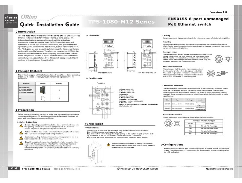
ORiNG TPS-1080-M12 User manual

ORiNG

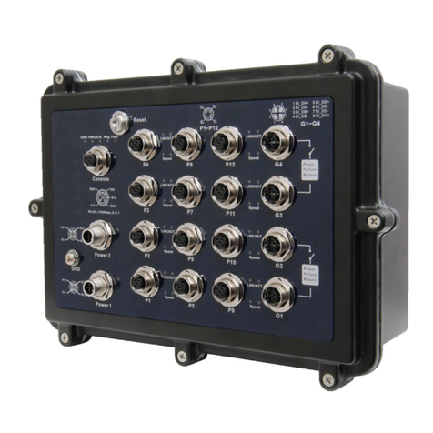
ORiNG TPS-1080-M12 User manual

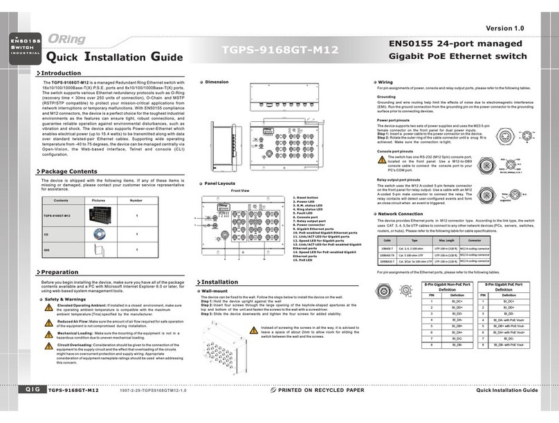
ORiNG TGPS-9168GT-M12 User manual

ORiNG

ORiNG TGPS-9168GT-M12 User manual

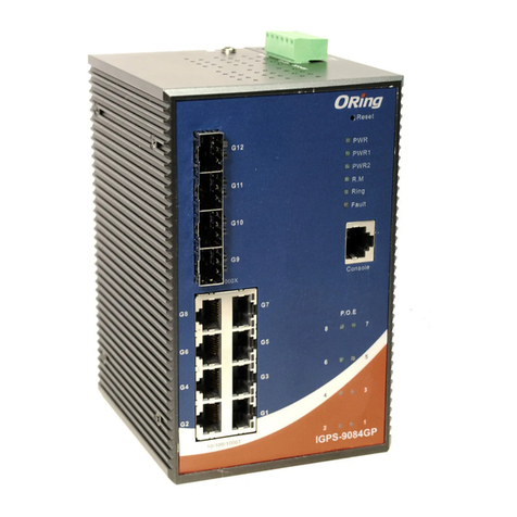
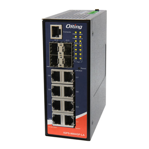
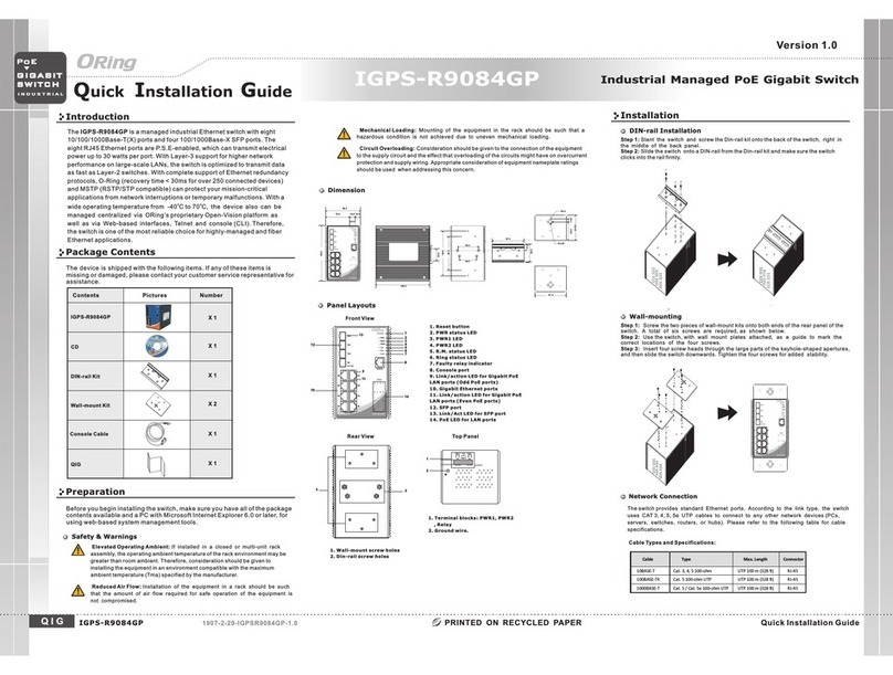
ORiNG IGPS-9084GP User manual

ORiNG

ORiNG IGPS-9084GP User manual

ORiNG TES-W9124GT-M12X-BP2-24V-IP54 User manual

ORiNG

ORiNG TES-W9124GT-M12X-BP2-24V-IP54 User manual

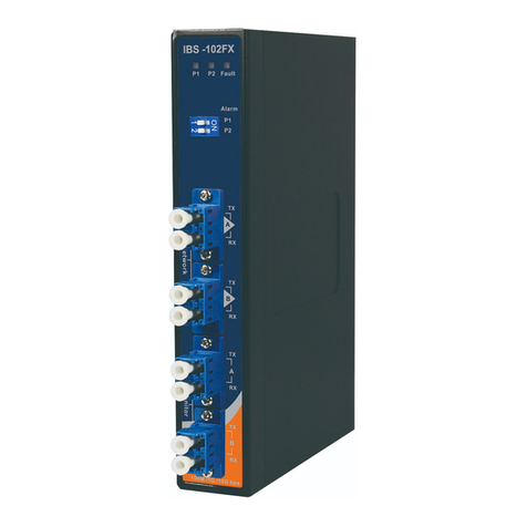
ORiNG IBS-102FX Series User manual

ORiNG

ORiNG IBS-102FX Series User manual

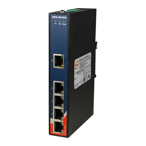
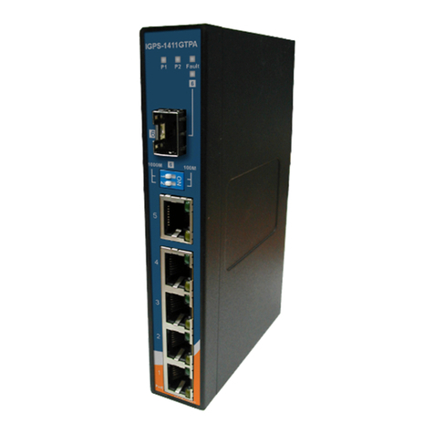
ORiNG IGPS-1041GTA User manual

ORiNG

ORiNG IGPS-1041GTA User manual

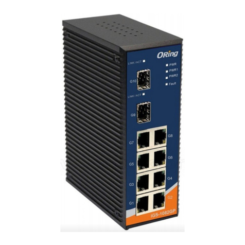
ORiNG IGS-1082GP User manual

ORiNG

ORiNG IGS-1082GP User manual

ORiNG TGPS-9084GT-M12X-BP2-24V User manual

ORiNG

ORiNG TGPS-9084GT-M12X-BP2-24V User manual

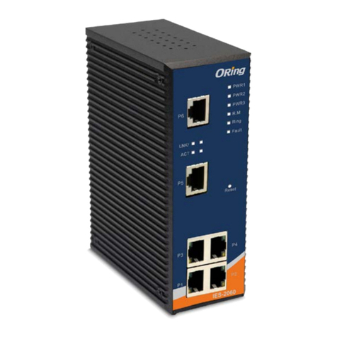
ORiNG IES-2060 Series User manual

ORiNG

ORiNG IES-2060 Series User manual

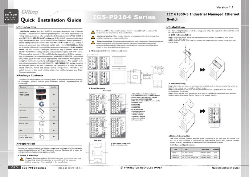
ORiNG IGS-P9164 Series User manual

ORiNG

ORiNG IGS-P9164 Series User manual

ORiNG IGPS-9084GP User manual

ORiNG

ORiNG IGPS-9084GP User manual

ORiNG IGPS-9084GP-LA User manual

ORiNG

ORiNG IGPS-9084GP-LA User manual

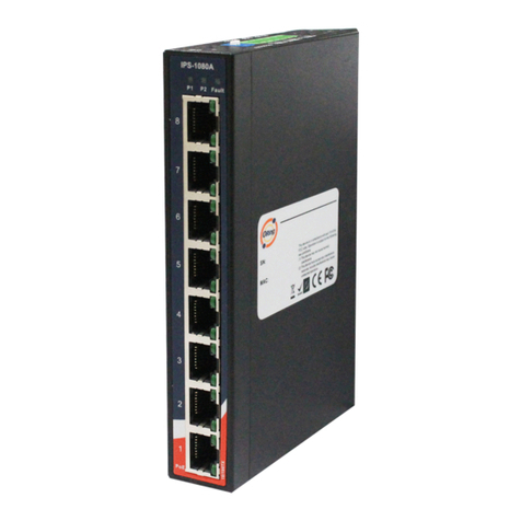
ORiNG IPS-1080A User manual

ORiNG

ORiNG IPS-1080A User manual

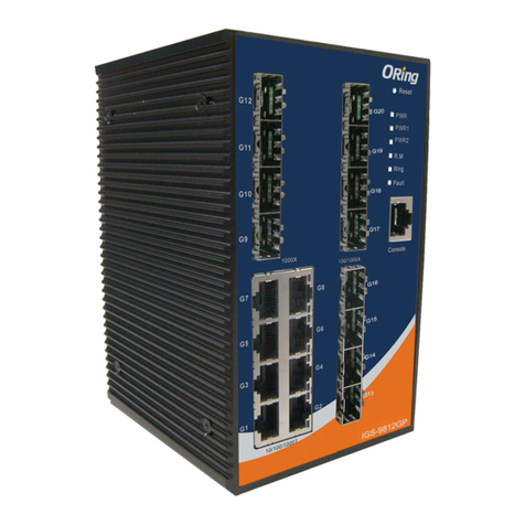
ORiNG IGS-9812GP User manual

ORiNG

ORiNG IGS-9812GP User manual

ORiNG IES-2050-M12 User manual

ORiNG

ORiNG IES-2050-M12 User manual

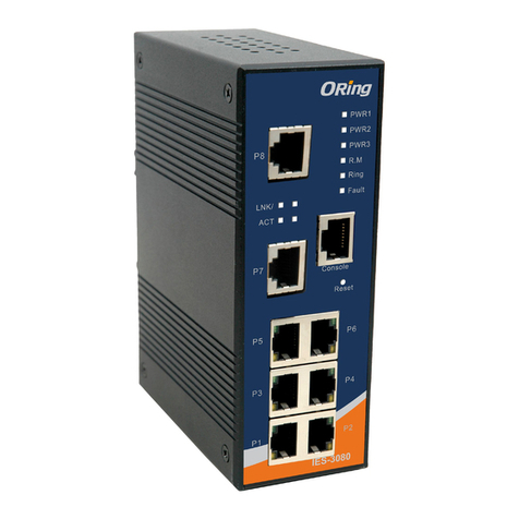
ORiNG IES-3080 Series User manual

ORiNG

ORiNG IES-3080 Series User manual

ORiNG IGS-P9164 Series User manual

ORiNG

ORiNG IGS-P9164 Series User manual

ORiNG IGPS-1411GTPA User manual

ORiNG

ORiNG IGPS-1411GTPA User manual

ORiNG IGPS-R9084GP User manual

ORiNG

ORiNG IGPS-R9084GP User manual

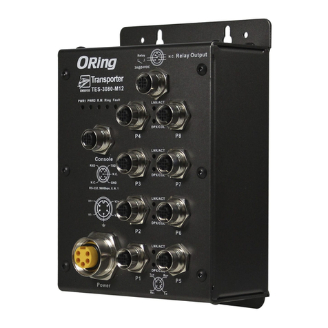
ORiNG TES-3080-M12 Series User manual

ORiNG

ORiNG TES-3080-M12 Series User manual

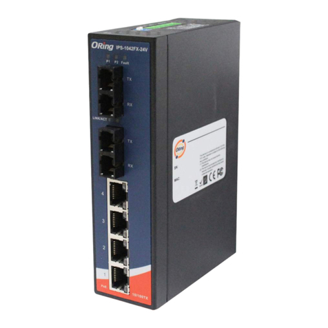
ORiNG IPS-1042FX-24V Series User manual

ORiNG

ORiNG IPS-1042FX-24V Series User manual

ORiNG EN50155 User manual

ORiNG

ORiNG EN50155 User manual

ORiNG TGPS-9168GT-M12-BP2-24V User manual

ORiNG

ORiNG TGPS-9168GT-M12-BP2-24V User manual

ORiNG IGPS-1042GPA User manual

ORiNG

ORiNG IGPS-1042GPA User manual

Popular Switch manuals by other brands

Leader LT 4441 instruction manual

Leader

Leader LT 4441 instruction manual

eks e-light 2MA manual

eks

eks e-light 2MA manual

Kobold SMN operating instructions

Kobold

Kobold SMN operating instructions

D-Link DGS-3100 SERIES Hardware installation guide

D-Link

D-Link DGS-3100 SERIES Hardware installation guide

Madison M8000-C Installation and Maintenance
Madison

Madison M8000-C Installation and Maintenance

Allen-Bradley 140G-M-EOP manual

Allen-Bradley

Allen-Bradley 140G-M-EOP manual

Acnodes KP802 user manual

Acnodes

Acnodes KP802 user manual

Draytek VigorSwitch P2280x quick start guide

Draytek

Draytek VigorSwitch P2280x quick start guide

Kramer VS-41AV user manual

Kramer

Kramer VS-41AV user manual

VXI EX7000 SERIES user manual

VXI

VXI EX7000 SERIES user manual

Grizzly T25448 instructions

Grizzly

Grizzly T25448 instructions

Hored PS2024G user manual

Hored

Hored PS2024G user manual

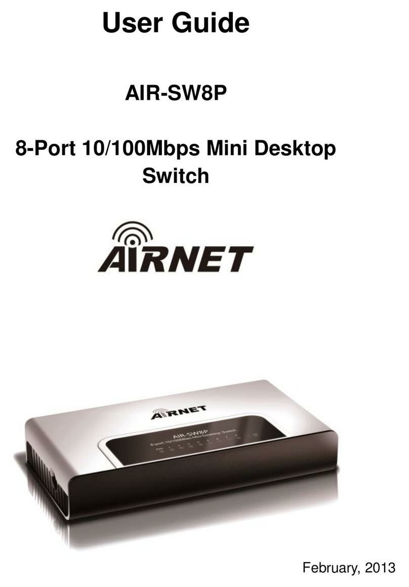
airnet AIR-SW8P user guide

airnet

airnet AIR-SW8P user guide

TRENDnet TK-1602R Specifications

TRENDnet

TRENDnet TK-1602R Specifications

Manhattan MondoHub II instructions

Manhattan

Manhattan MondoHub II instructions

Avaya Cajun P333T user guide

Avaya

Avaya Cajun P333T user guide

Lindy SC5 user guide

Lindy

Lindy SC5 user guide

Intel EXPRESS 330T quick start guide

Intel

Intel EXPRESS 330T quick start guide

manuals.online logo
manuals.online logoBrands
  • About & Mission
  • Contact us
  • Privacy Policy
  • Terms and Conditions

Copyright 2025 Manuals.Online. All Rights Reserved.