sPecIFIcatIoNs
Frequency VHF 44-230 MHz
Range UHF 520-820 MHz
Max Gain VHF: 22-28 dB (W Models ONLY)
UHF: 34 dB
Noise VHF<3 dB
Figure UHF<2.5 dB
Output 105 dB
Figure DIN45004B @(-60 dB IMR)
Gain VHF Tilt Control 14-10 dB
Controls UHF 10 dB
Supply PSK08/F 17.5 V AC and
Voltage PSK06/F 14 V DC @ 80 mA
(PSK02 may also be used).
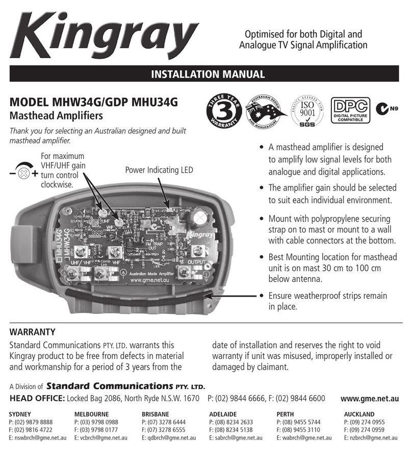
MHW34G/GDP ONLY
Aus Pager Filter -25 dB @ 148 MHz
NZ Pager Filter -25 dB @ 158 MHz
FM Filter -25 dB @ 88 - 108 MHz
Bare back the cable as per diagram, pushing the earth
braid back over the black sheath. Connect the earth
to the saddle and the centre conductor to the screw
connection.
Bare Back Cable with a Cable
Stripper or Stanley Knife.
INstallatIoN
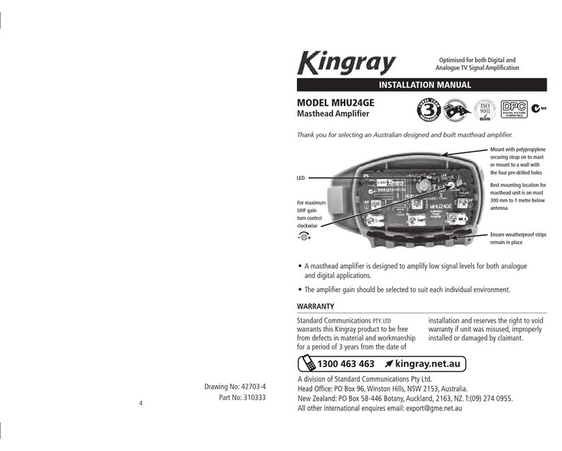
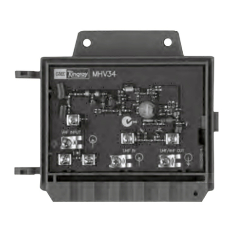
All these models are designed for combined or separate antenna inputs.
Combined Imput Separate Imput
Leave the link
on for a
combined
antenna
or
Remove for
a separate
antenna
FIlter oPtIoNs
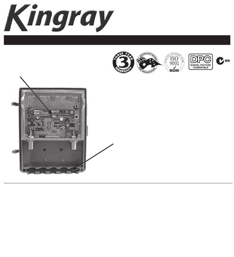
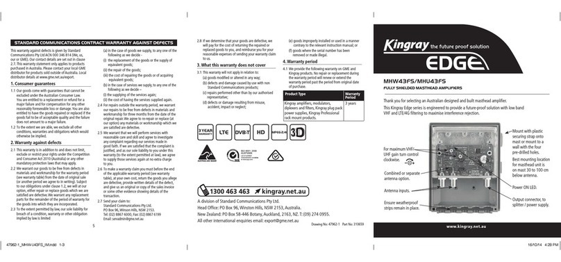
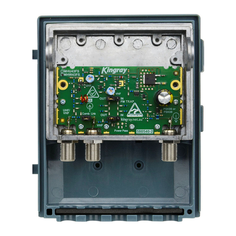
The FM and pager filter are located in the
MHW models only.
The -25 dB Band Stop FM Filter may be disabled by
simply removing the shorting link and placing it on
the specified terminals. The FM trap must be in the out
position to view television channel 3.
Pager Filter set to attenuate between 148 - 158 MHz.
(Pager Filter maybe removed if you need
to amplify 5A, simply remove 2 coils as
indicated on the PCB above the VHF input.)
PoWerING INlINe oPtIoNs
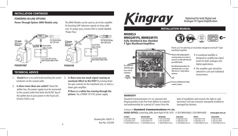
Power Through Option: MHU Models only. The UHF Models can be used as an in-line amplifier for
boosting UHF television signals on long run cable runs.
To power pass connect link to both pins on socket.
2 3
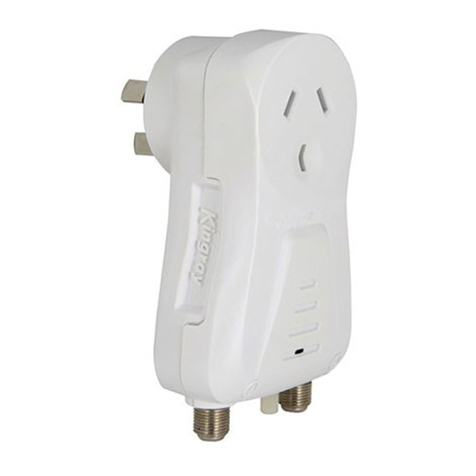
Please note: an F Type Adaptor has been included,
in all Kingray F Type Power Supplies to fit an F Type
wall plate. However, the insert from the wall plate
can be removed and the Power Injector may be fitted
directly with the locking nut provided.
PSK06F/08F PSK06/08
