KITO N6 Series User manual

OM-N6CEOZ-MGE-01
OWNER’S (OPERATOR’S) MANUAL AND
SAFETY INSTRUCTIONS
FOR KITO URETHANE WHEEL CRANES
N6SERIES
ALWAYS SAVE THIS BOOK FOR FUTURE REFERENCE.

Thank you for purchasing the Kito N6 series Urethane wheel type Crane.
This crane has urethane coated steel track wheels. Light weight, quiet and stable,
the crane is designed to improve work efficiency.
Owing to thorough quality controls, this crane has been manufactured to satisfy
requirements for durability.
However, improper handling, usage or maintenance may result in unforeseen
accident or injury. Therefore, read thoroughly this manual before using the
equipment.
Application notes;
This manual is exclusively applied to N6C model cranes.Almost all parts of N6C model
cranes have no interchangeability with N6 model cranes.
All of N6C type end carriages can not be assembled with G1 type geared motor but with
G1B type geared motor only.
<CONTENS>
1. Definitions...............................................................................................................1
2. Intended purpose.....................................................................................................1
3. Before use ...............................................................................................................1
4. Cranes .....................................................................................................................3
5. Assembly, wiring and test run.................................................................................9
6. For better usage.....................................................................................................21
7. Maintenance and inspections ................................................................................21
8. track wheel disassembly and assembly.................................................................25
9. Power supply.........................................................................................................27
10. Troubleshooting ....................................................................................................28
11. Warranty................................................................................................................29
12. Parts list.................................................................................................................30

- 1 -
1. DEFINITIONS
DANGER : indicates an imminently hazardous situation which, if not avoided, will result
in death or serious injury.
WARNING : indicates a potentially hazardous situation which, if not avoided, could result
in death or serious injury.
CAUION : indicates a potentially hazardous situation which, if not avoided, may result
in minor or moderate injury. It may also be used to alert against unsafe
practices.
WLL: indicates maximum mass (working load limit) which a crane is designed to support in general service.
Under WLL, all values are indicated in t (ton).
2. INTENDED PURPOSE
This crane has been designed for vertically lifting, lowering and horizontally carrying loads by means of the
pendant push button switches, under normal atmospheric conditions of the work place.
3. BEFORE USE
3.1 Safety summary
Danger exists when heavy loads are transported, particularly when the equipment is not being used
properly or is poorly maintained. Because accidents and serious injury could result, special safety
precautions apply to the operation, maintenance and inspection of the KITO crane.
WARNING : ALWAYS operate, inspect and maintain this Crane in accordance with
applicable safety codes and regulations.
Following these simple rules can help to avoid hoisting accidents;
WARNING : IMPROPER crane use could result in death or serious injury. To avoid these
hazards.
3.1.1 Before and during operation
NEVER lift or transport loads over or near people.
NEVER use a crane for lifting, supporting or transporting people.
NEVER leave a suspended load unattended.
NEVER lift more than the rated capacity.
NEVER reverse crane operation abruptly or inch the crane excessively in travel.

- 2 -
NEVER pull a load from an extreme angle.
NEVER allow the crane to impact the stopper or other crane.
ALWAYS inspect the crane before use and at periodic intervals.
ALWAYS pay attention to load swing while operating the crane.
ALWAYS be aware of what is going on in the vicinity of the crane during use.
ALWAYS keep travel and traverse paths, and shelters, unobstructed.
ALWAYS operate the push buttons from a location from where both the hook and load can be seen.
ALWAYS check slings and loads are properly installed before use.
ALWAYS walk behind or alongside a suspended load, and keep eyes looking forward, while operating the crane.
ALWAYS read the “Safety Instructions” for your hoist and trolley respectively
provided.----------------------------------------------------------------------------------
3.1.2 Maintenance and checks
ALWAYS have maintenance, check and repairs performed by a qualified person.
ALWAYS place an “OUT OF SERVICE” sign on the crane when performing maintenance, checks or repairs.
ALWAYS turn OFF power to the hoist, trolley and crane before performing maintenance, checks
or repairs.
ALWAYS wear a helmet and safety belt when performing maintenance, checks or repairs.

- 3 -
4. Cranes
4.1 Features
[Geared motor]
(a) Employs an electromagnetic brake to mechanically adjust brake torque in stopping.
(b) Travel is kept quiet because of the helical gear used in the reduction gear.
(c) Comes in 3 models with different single speed specification (low, standard and high) and 1 model
with dual speed specification (Reduction ratio of 4:1).
[Low-head end carriage]
(a) Track wheels are easily taken off. This greatly shortens installation and maintenance work.
(b) High tension bolts (H.T.B) are used to couple the end carriage to the girder as standard for low-
head type.
(c) The center punch for girder installation holes is marked on the end carriage to make centering
easier.
(d) The end carriage is coated with a red primer when shipped from the factory.
(e) Travel is kept quiet with urethanecoated wheels. The wheels are cold and weather resistant, and
water resistant.
(f) Travel is kept quiet with a pinion L made from nylon. The pinion is weather and wear resistant.
(g) The end carriage uses press formed frames designed by Kito.
[Overhead end carriage]
(a) The end carriage has an open frame construction to facilitate track wheel maintenance.
(b) The end carriage is built with side rollers to keep travel smooth and stable.
(c) The centerpunchfor girder installation holes, girders andtravel rails are marked on theend carriage
to make centering easier.
(d) Span is easily adjusted on-site because the end carriage is coupled to the frame by bolts.
(e) The end carriage is coated with a red primer when shipped from the factory.
(f) Travel is kept quiet with urethanecoated wheels. The wheels are cold and weather resistant, and
water resistant.
(g) The end carriage uses press formed frames designed by Kito.
[Double girder end carriage]
(a) The end carriage has an open frame construction to facilitate track wheel maintenance.
(b) The end carriage is built with side rollers to keep travel smooth and stable.
(c) The center punch for girders and travel rails are marked on the end carriage to make centering
easier.
(d) The end carriage uses press formed frames (channel type) designed by Kito.
(e) The end carriage is coated with a red primer when shipped from the factory.
(f) Travel is kept quiet with urethanecoated wheels. The wheels are cold and weather resistant, and
water resistant.

- 4 -
General view (For your reference)
[Low-head crane]
[Overhead crane]
[Double girder crane]

- 5 -
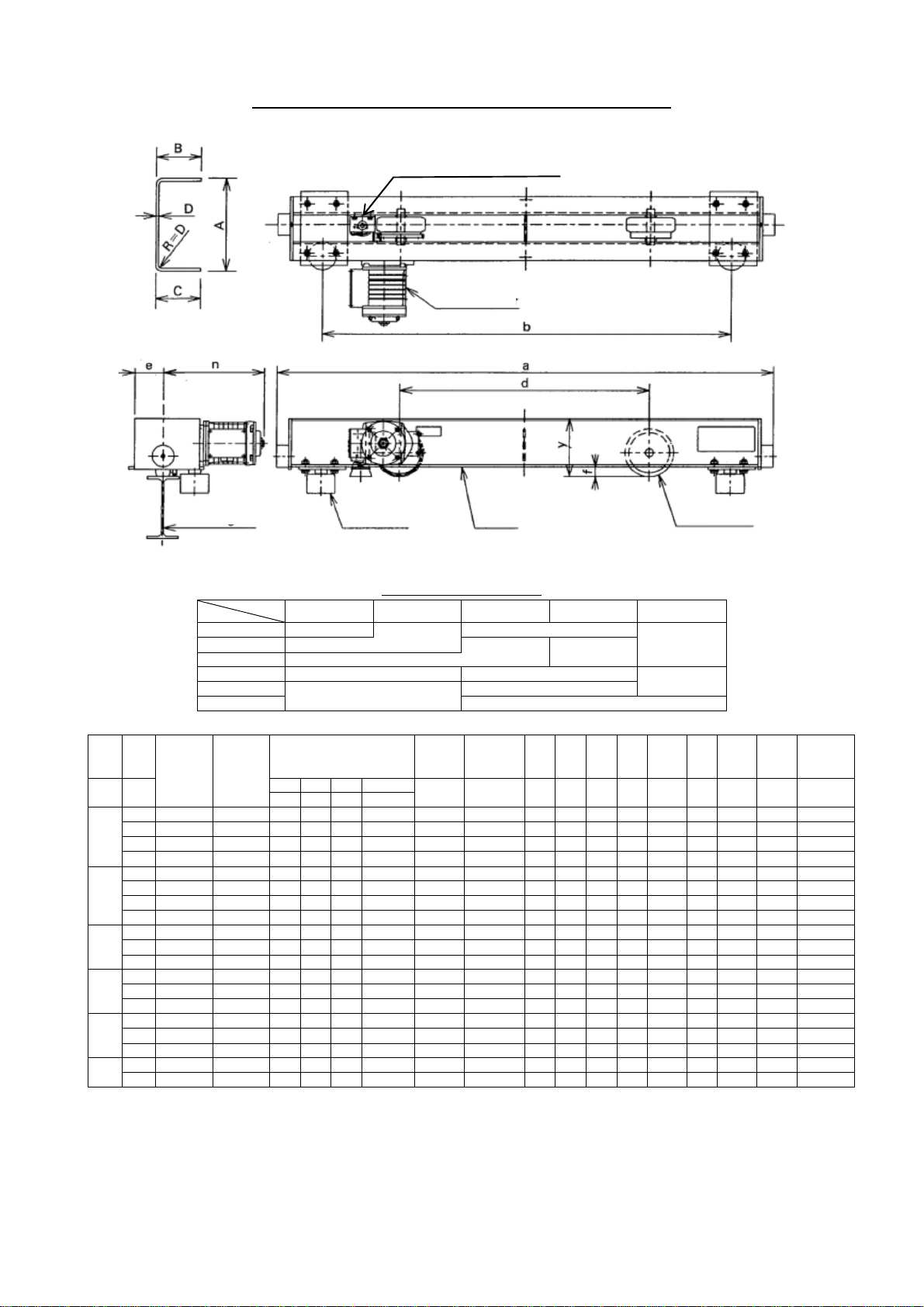
4.2 Specifications and outer appearance
Urethane wheel low-head type motorized end carriage
Frame size ABCD (mm)
Span (m)
WLL (t) 6 9
1 15560606
2 20080809
WLL M
ax.
span Type Code Traveling motor output [kW2]
50/60Hz [m/min] Wheel
diameter
Applicable
traveling rail
width a d m u x *2y*1n
Max.
wheel
pressure
Net
weight
[t] [m] L S H SD [mm] [mm] [mm] [mm] [mm] [mm] [mm] [mm] [mm] [kg] [kg]
10/12 20/24 30/36 20:5/24:6
1 9 CEL010-9 N6CL310V 0.25 0.20 0.25 0.25/0.063 95 125 to 150 1500 1060 t+171 34 241-t/2 121 t/2+288 390 143
2 9 CEL020-9 N6CL320V 0.4 0.4 0.75 0.4/0.1 125 125 to 150 1500 1060 t+211 35 281-t/2 165 t/2+336 710 231
*1: Dimensions for standard speed geared motor
*2: Height from the traveling surface of the rail to the top point of the end carriage.
WLL: Working load limit
Travelling rail
Track wheel
Stay holder
Geared motor
Frame
Section of frame
Earth Device
(
Optio
nal ite
m
)
- 6 -
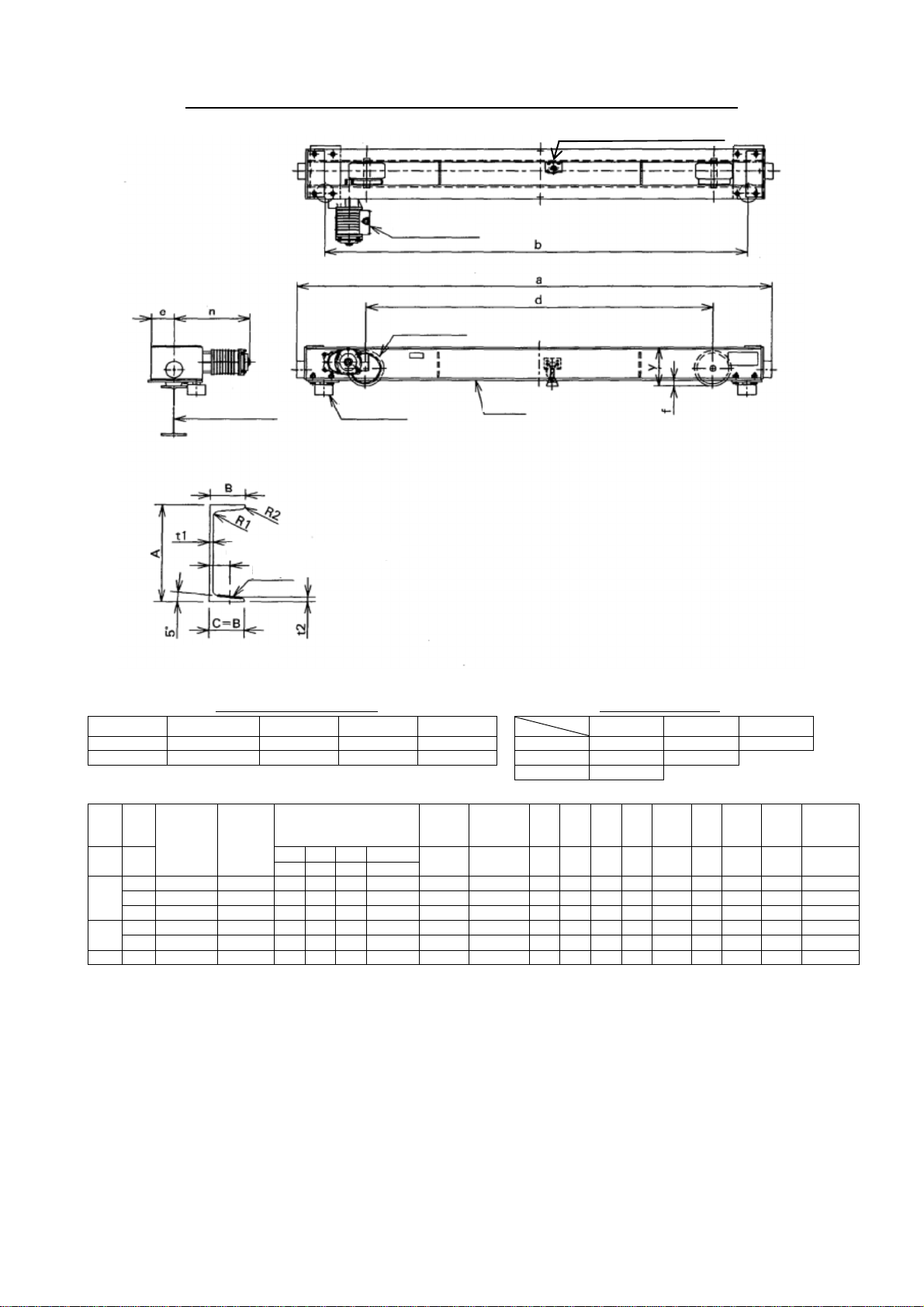
Urethane wheel overhead type motorized end carriage
Frame size ABCD (mm)
S
pan (m)
WLL (t)
9 12 15 18 21
1 15560606 20070706
2 1556060620095956 20090909
3 20095956
5 20095956 200808092401051059
7.5 200808092401051059
10 3001251259
WLL M
ax.
span Type Code Traveling motor output [kW2]
50/60Hz [m/min] Wheel
diameter
Applicable
traveling rail
width a d m u x *2y*1n
Max.
wheel
pressure Net weight
[t] [m] L S H SD [mm] [mm] [mm] [mm] [mm] [mm] [mm] [mm] [mm] [kg] [kg]
10/12 20/24 30/36 20:5/24:6
1
9 CEO010-9 N6CO310E 0.25 0.25 0.25 0.25/0.063 155 100 to 150 1586 1307 800 92 32 188 317 800 156
12 CEO020-12 N6CO420E 0.4 0.4 0.4 0.4/0.1 175 150 to 200 1696 1445 900 112 32 188 383 1500 202
18 CEO010-18 N6CO610E 0.4 0.4 0.4 0.4/0.1 175 150 to 200 2356 2105 1200 122 32 233 383 1500 265
21 CEO030-21 N6CO730E 0.75 0.75 0.75 0.75/0.19 220 150 to 200 2792 2499 1400 147 39 239 454 3400 502
2
12 CEO020-12 N6CO420E 0.4 0.4 0.4 0.4/0.1 175 150 to 200 1696 1445 900 112 32 188 383 1500 202
15 CEO030-15 N6CO530E 0.75 0.75 0.75 0.75/0.19 220 150 to 200 2082 1761 1000 152 39 239 451 3400 384
18 CEO030-18 N6CO630E 0.75 0.75 0.75 0.75/0.19 220 150 to 200 2422 2101 1200 152 39 239 451 3400 398
21 CEO030-21 N6CO730E 0.75 0.75 0.75 0.75/0.19 220 150 to 200 2792 2499 1400 147 39 239 454 3400 502
315 CEO030-15 N6CO530E 0.75 0.75 0.75 0.75/0.19 220 150 to 200 2082 1761 1000 152 39 239 451 3400 384
18 CEO030-18 N6CO630E 0.75 0.75 0.75 0.75/0.19 220 150 to 200 2422 2101 1200 152 39 239 451 3400 384
21 CEO030-21 N6CO730E 0.75 0.75 0.75 0.75/0.19 220 150 to 200 2792 2499 1400 147 39 239 454 3400 502
512 CEO050-12 N6CO450E 0.75 0.75 1.5 0.75/0.19 220 150 to 200 1852 1531 900 152 39 239 451 3400 355
18 CEO050-18 N6CO650E 1.5 1.5 1.5 1.5/0.38 260 150 to 200 2402 2106 1200 139 39 239 540 4200 543
21 CEO075-21 N6CO775E 1.5 1.5 1.5 1.5/0.38 340 150 to 200 2821 2506 1400 184 39 279 553 6300 665
7.5 12 CEO100-12 N6CO411E 1.5 1.5 1.5 1.5/0.38 340 150 to 200 2081 1766 900 159 39 239 553 6300 525
18 CEO075-18 N6CO675E 1.5 1.5 1.5 1.5/0.38 340 150 to 200 2421 2106 1200 184 39 279 553 6300 627
21 CEO075-21 N6CO775E 1.5 1.5 1.5 1.5/0.38 340 150 to 200 2821 2506 1400 184 39 279 553 6300 665
10 12 CEO100-12 N6CO411E 1.5 1.5 1.5 1.5/0.38 340 150 to 200 2081 1766 900 159 39 239 553 6300 525
21 CEO100-21 N6CO711E 1.5 1.5 1.52 1.5/0.38 440 200 to 250 2849 2509 1400 234 46 346 592 8300 1027[1220]
*1: Dimensions for standard speed geared motor
*2: height from the traveling surface of the rail to the top point of the end carriage.
WLL: Working load limit
Section of frame
Travelling rail
Track wheel
Frame
Side roller
Geared motor
Earth Device
(
Optio
nal ite
m
)
- 7 -
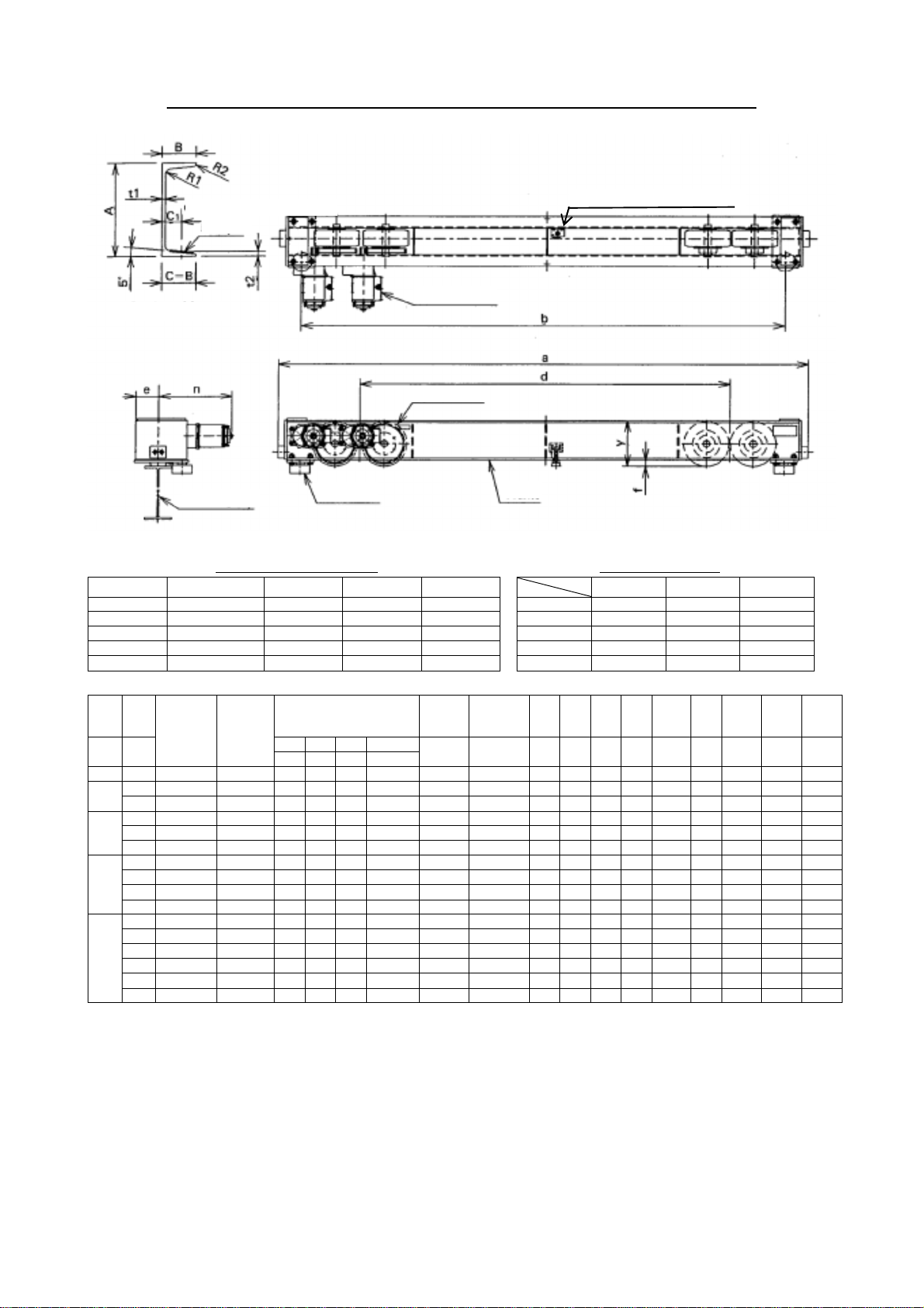
Urethane wheel overhead type double girder motorized end carriage (1)
Frame size ABt1t2 (mm) Symbol of frame size
Symbol Size R1 R2 C1
S
pan (m)
WLL (t)
15 21 27
FRM1 200807.511 12 6 47 3 FRM1 FRM1 FRM2
FRM2 25090913 14 7 53 5
7.5 FRM2
WLL M
ax.
span Type Code Traveling motor output [kW2]
50/60Hz [m/min] Wheel
diameter
Applicable
traveling rail
width a d m u x *2y*1n
Max.
wheel
pressure Net weight
[t] [m] L S H SD [mm] [mm] [mm] [mm] [mm] [mm] [mm] [mm] [mm] [kg] [kg]
10/12 20/24 30/36 20:5/24:6
315 WCO030-15 N6KO530E 0.75 0.75 1.5 0.75/0.19 220 150 to 200 2851 2539 2085 137 39 239 453 3400 524
21 WCO030-21 N6KO730E 1.5 1.5 1.5 1.5/0.38 260 150 to 200 3111 2796 2295 139 39 239 538 4200 653
27 WCO030-27 N6KO930E 1.5 1.5 1.5 1.5/0.38 300 150 to 200 3211 2896 2140 159 39 239 548 4400 881
515 WCO030-21 N6KO730E 1.5 1.5 1.5 1.5/0.38 260 150 to 200 3111 2796 2295 139 39 239 538 4200 653
21 WCO075-15 N6KO575E 1.5 1.5 1.5 1.5/0.38 340 150 to 200 3091 2776 2230 169 39 239 553 6300 930
7.5 15 WCO075-15 N6KO575E 1.5 1.5 1.5 1.5/0.38 340 150 to 200 3091 2776 2230 169 39 239 553 6300 930
*1: Dimensions for standard speed geared motor
*2: Height from the traveling surface of the rail to the top point of the end carriage.
WLL: Working load limit
Travelling rail
Track wheel
Frame
Side roller
Geared motor
C1: distance to middle of slope
5
slope
Section of frame
Earth Device
(
Optio
nal item
)
- 8 -
Urethane wheel overhead type with double girder motorized end carriage (2)
Frame size ABt1t2 (mm) Symbol of frame size
Symbol Size R1 R2 C1
S
pan (m)
WLL (t)
15 21 27
FRM1 25090913 14 7 53 5
FRM2 30090913 14 7 53 7.5 FRM1 FRM1 FRM2
FRM3 300901015.5 19 9.5 55 10
FRM4 38010010.516 18 9 60 15 FRM3 FRM4
FRM5 3801001320 24 12 62 20 FRM4 FRM5 FRM5
WLL M
ax.
span Type Code Traveling motor output [kW2]
50/60Hz [m/min] Wheel
diameter
Applicable
traveling rail
width a d m u x *2y *1n
Max.
wheel
pressure
Net
weight
[t] [m] L S H SD [mm] [mm] [mm] [mm] [mm] [mm] [mm] [mm] [mm] [kg] [kg]
10/12 20/24 30/36 20:5/24:6
5 27 WCO075-21 N6KO775E 1.52 1.52 1.52 1.5/0.382 2602 175 to 200 3771 3456 2700 149 39 289 540 4200 1150
7.5 21 WCO075-21 N6KO775E 1.52 1.52 1.52 1.5/0.382 2602 175 to 200 3771 3456 2700 149 39 289 540 4200 1160
27 WCO075-27 N6KO975E 1.52 1.52 1.52 1.5/0.382 3002 175 to 200 4059 3701 2900 159 46 346 548 4400 1438
10 15 WCO075-21 N6KO775E 1.52 1.52 1.52 1.5/0.382 2602 175 to 200 3771 3456 2700 149 39 289 540 4200 1160
21 WCO075-27 N6KO975E 1.52 1.52 1.52 1.5/0.382 3002 175 to 200 4059 3701 2900 159 46 346 548 4400 1438
27 WCO150-21 N6KO715E 1.52 1.52 1.52 1.5/0.382 3402 200 to 250 4412 4063 3220 179 46 426 554 6300 1672
15
15 WCO150-15 N6KO515E 1.52 1.52 1.52 1.5/0.382 3402 200 to 250 3992 3643 2790 169 46 346 554 6300 1378
21 WCO150-21 N6KO715E 1.52 1.52 1.52 1.5/0.382 3402 200 to 250 4412 4063 3220 179 46 426 554 6300 1672
27 WCO200-21 N6KO721E 1.52 1.52 - 1.5/0.382 3402 250 to 300 5172 4823 3800 209 46 426 593 8300 2575
27 WCO200-21 N6KO721E - - 2.22 - 4402 250 to 300 5292 4943 3840 209 46 426 709 8300 2700
20
15 WCO200-15 N6KO521E 1.52 1.52 - 1.5/0.382 4402 250 to 300 4742 4393 3380 209 46 426 593 8300 2214
15 WCO200-15 N6KO521E - - 2.22 - 4402 250 to 300 4872 4523 3420 209 46 426 709 8300 2336
21 WCO200-21 N6KO721E 1.52 1.52 - 1.5/0.382 4402 250 to 300 5172 4823 3800 209 46 426 593 8300 2575
21 WCO200-21 N6KO721E - - 2.22 - 4402 250 to 300 5292 4943 3840 209 46 426 709 8300 2700
27 WCO200-27 N6KO921E 1.52 1.52 - 1.5/0.382 4402 250 to 300 5422 5073 4070 209 46 426 593 8300 2944
27 WCO200-27 N6KO921E - - 2.22 - 4402 250 to 300 5552 5203 4110 209 46 426 709 8300 3071
*1: Dimensions for standard speed geared motor
*2: Height from the traveling surface of the rail to the top point of the end carriage.
WLL: Working load limit
distance to middle of slope
5
slope
Section of frame
Geared motor
Travelling rail
Side roller
Frame
Track wheel
Earth Device
(
Optio
nal ite
m
)
- 9 -
5. Assembly, wiring and test run
WARNING : ALWAYS make sure that the load supporting structures and load attaching
device are strong enough to hold the weight of load and hoist.
Have all assembly works by the authorized people. Off-limits to unauthorized
people in assembly works area.
5.1 Assembly
For detailed assembly instructions, refer to the urethane wheel crane’s assembly manual. The end
carriage can be easily set on the travel rails with the following procedure.
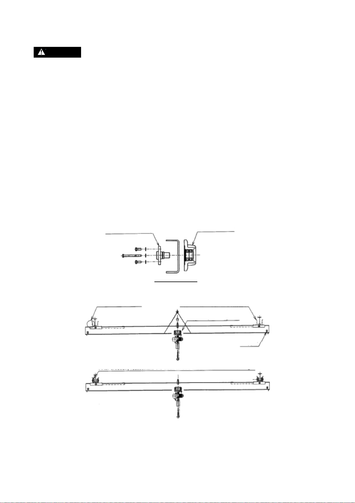
<Low-head type carriage>
(a) Detach all track wheels and axles from the end carriage as shown in Fig. 1.
The end carriage frame can be erected without detaching it from the girder. Reassemble the track
wheels and axles when the end carriage is in position.
There is always the risk of the hoist and trolley moving when installing, therefore it is easy to fix
them to the girder.Also, pay attention when assembling with the power supply cable, junction cable
and other accessories.
(b) Installing as shown in Fig. 1.
Fig. 1
Track wheel axle ass’y
Track wheel ass’y
Detail of track wheel
Track wheel position
Erect frame and girder together.
Fix the hoist and trolley to
the girder.
Stopper
After
erection, reassemble the track wheels and axles in the end carriage.
- 10 -
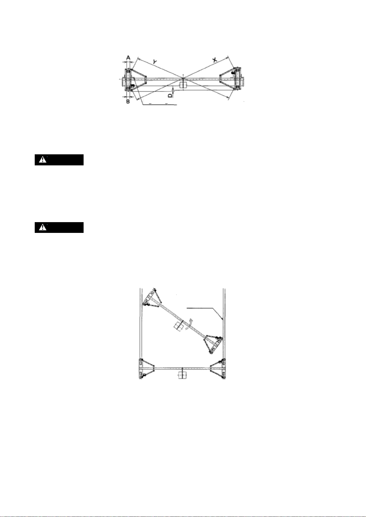
(c) Precautions in installation (Refer to Fig. 2)
Pay attention to the following points when coupling the end carriage to the girder on site.
Fig. 2
Keep the end carriage frames parallel (Aand B should be the same).
Minimize any discrepancy between the left and right end carriage frames position (D should be
minimized).
WARNING : If improperly assembled and installed, the crane will repeatedly strike the
stopper on the travel rail. This may cause bolts to loosen or other trouble.
Keep the end carriage at a right angle to the girder.
Minimize any discrepancy in angling between the left and right end carriage frames (X and Y
dimensions).
WARNING : When installing the hoist and trolley on the girder, refer to the “Safety
Instructions” for your hoist and trolley respectively provided.
<Overhead type crane>
(a) Generally, the simple way to erect the completed crane is shown in Fig. 3. Lift crane into position
of following figure, then turn the crane so as to fit on the travel rails.
Fig. 3
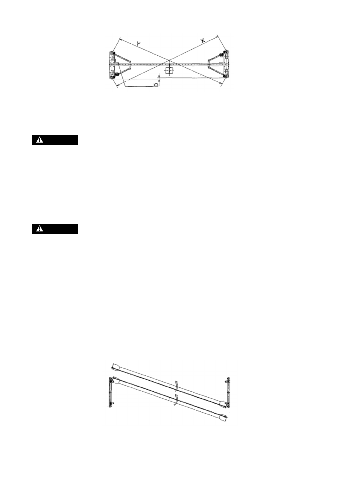
(b) Precautions in installation (Refer to Fig. 4).
The end carriage comes set at a right angle to the girder and squared to size when delivered,
nevertheless, pay attention to the following points when coupling the end carriage to the girder on-
site.
Right angle
Travel rail
- 11 -
Fig. 4
Minimize any discrepancy between the left and right end carriage frames position (D should be
minimized).
WARNING : If improperly assembled and installed, the crane will repeatedly strike the
stopper on the travel rail. This may cause bolts to loosen or other trouble.
Keep the end carriage at a right angle to the girder.
Minimize any discrepancy in angling between the left and right end carriage frames (X and Y
dimensions).
When using a urethane wheel crane, please lay a dedicated earth wire. When using an earth brush,
do not paint on the running surface of the track wheel. (Painting can also cause the track wheel to
slip)
WARNING : When installing the hoist and trolley on the girder, refer to the “Safety
Instructions” for your hoist and trolley respectively provided.
<Double girder crane>
Many double girder cranes come equipped with peripheral equipment and accessories, and there are
equally as many different ways to erect them.
(a) If the crane can be erected with the left and right end carriage frames attached to the girder, then
erect the crane according to the same procedure described for overhead cranes, check dimensions
after erecting the equipment, and adjust where necessary.
(b) If the crane cannot be erected with the left and right end carriage frames attached to the girder, then
first erect the end carriage frames on the travel rails as shown in Fig. 5. Next, turn the girders so as
to fit between the travel rails and lift into position, and attach the girders to the end carriage frames
on the travel rail.When assembling, set the end carriages to a right angle with the girder and square
with one another, and adjust span as necessary. (Refer to Fig.5)
Fig. 5
Right angle
- 12 -
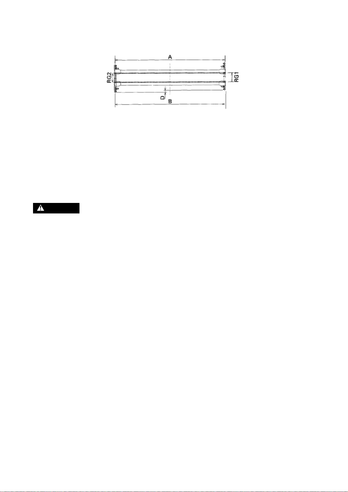
(c) Precautions in installation (Refer to Fig. 6).
Pay attention to the following points when coupling the end carriage to the girder on-site.
Fig. 6
Minimize any discrepancy between the left and right end carriage frames position (D should be
minimized). If improperly assembled and installed, the crane will repeatedly strike the stopper on
the travel rail. This may cause bolts to loosen or other trouble.
Minimize any discrepancy in rail gauge between the traverse rails (RG1 and RG2 dimensions9.
Keep the end carriage frames parallel (Aand B should be the same).
5.2 Wiring
DANGER : ALWAYS turn OFF power source or breaker switch to prevent electric shock
before beginning the wiring process.
HAVE all wiring performed by an authorized electrician.
Power can be supplied by the cable power supply, tro-reel, or trolley duct systems. For wiring from the
power source to the crane’s control box, refer to “9. Power supply” in this manual.
5.2.1 Control box internal wiring
Control box wiring differs depending on whether the emergency stop device (option) to the push
button switch is attached or not, and whether an electric chain hoist or rope hoist is used. Check
wiring diagrams before wiring.
For your reference, typical wiring schemes are shown in Figs. 7 through 12.
- 13 -
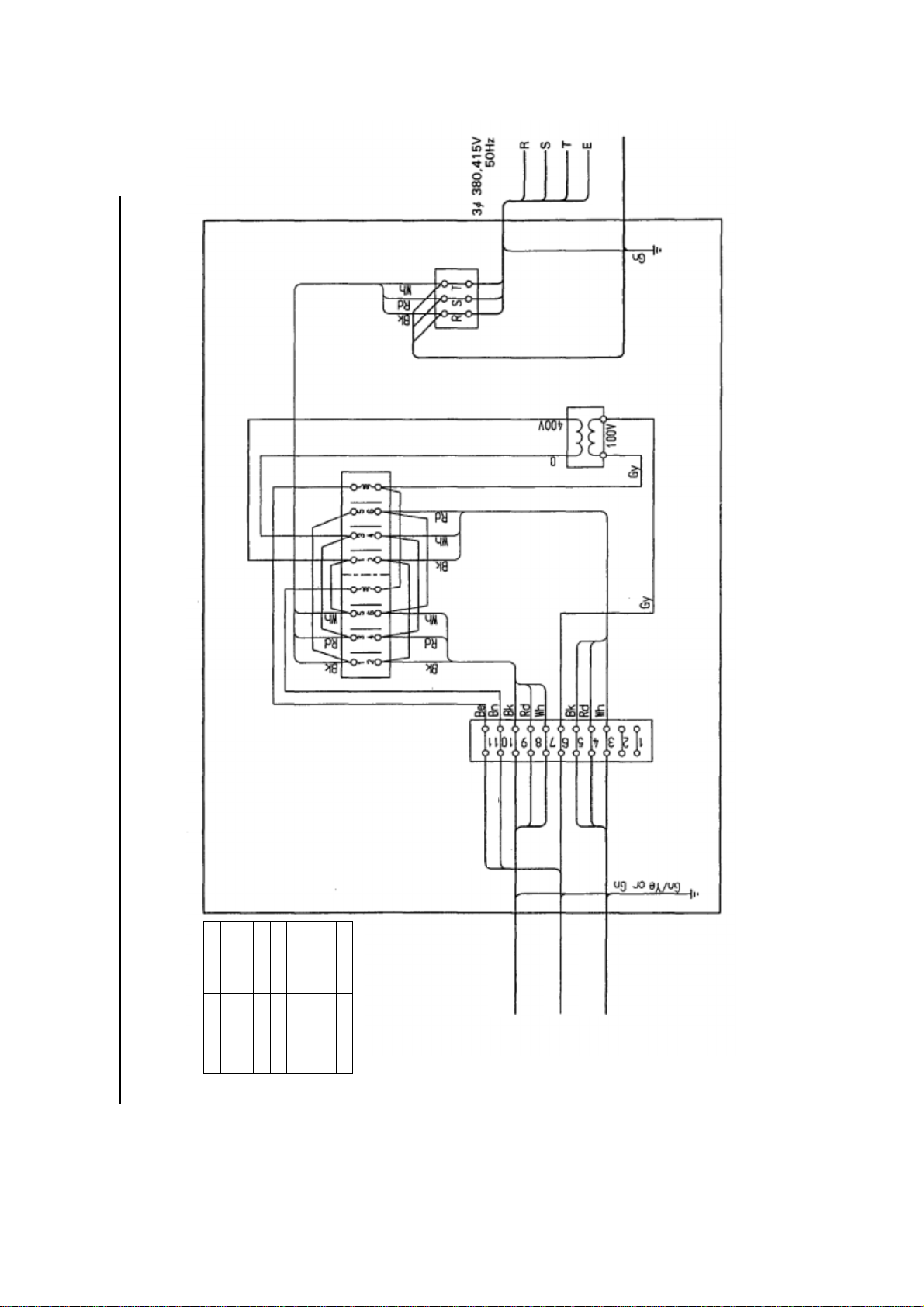
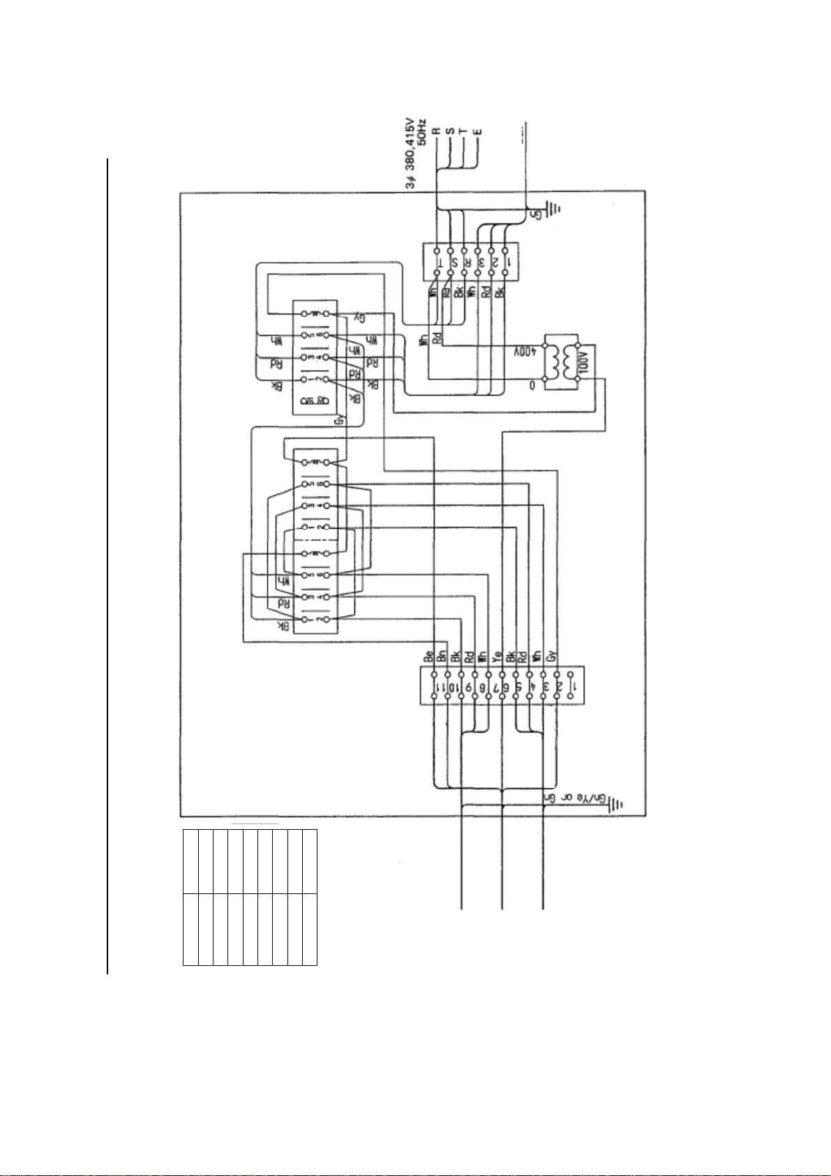
5.2.1
Electric traversing wire rope hoist with motorized trolley single speed (end carriage), without emergency stop device.
Hoist control
box
Fir travelling
Fir travelling
For control circuit
Geared motor
of crane
Hoist control box
Geared motor
of crane
Abbreviation
Bk
Rd
Wh
Gy
Bn
Be
Gn
Gn/Ye
Color
Black
Red
White
Gray
Brown
Blue
Green
Green & Yellow
Fig. 7
- 14 -
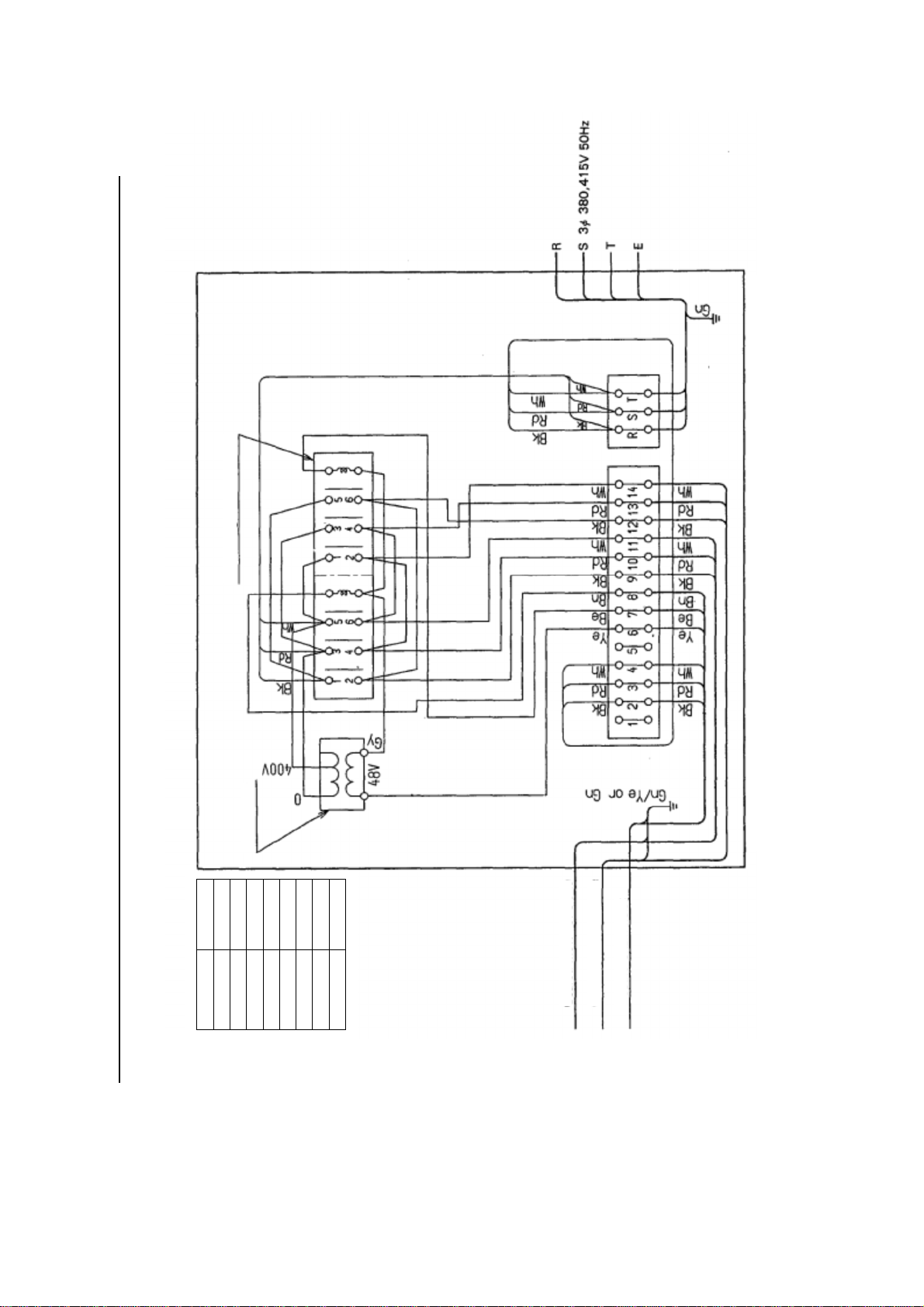
5.2.1
Electric traversing wire rope hoist with motorized trolley single speed (end carriage), without emergency stop device.
Fig. 8
Hoist control
box
Fir travelling
Fir travelling
Geared motor
of crane
Hoist control box
Geared motor
of crane
For
control circuit
For emergency stop
Abbreviation
Bk
Rd
Wh
Gy
Bn
Be
Gn
Gn/Ye
Color
Black
Red
White
Gray
Brown
Blue
Green
Green & Yellow
- 15 -
Abbreviation
Bk
Rd
Wh
Gy
Bn
Be
Gn
Gn/Ye
Color
Black
Red
White
Gray
Brown
Blue
Green
Green & Yellow
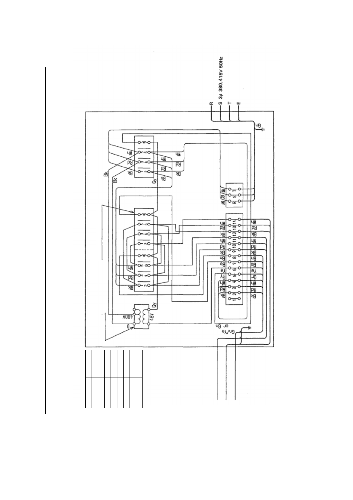
5.2.1
Electric traversing wire rope hoist with motorized trolley single speed (end carriage), without emergency stop device.
Fig. 9
Geared motor of crane
Electric Chain hoist
Geared motor of crane
Transformer
Electromagnetic contractor
* A disuse wire
among three wires of the primary side of the transformer shall be isolated and rolled to be fixed securely.
- 16 -
5.2.1
Electric traversing wire rope hoist with motorized trolley single speed (end carriage), without emergency stop device.
Fig. 10
Geared motor of crane
Electric Chain hoist
Geared motor of crane
Transformer
Electromagnetic contractor
Abbreviation
Bk
Rd
Wh
Gy
Bn
Be
Gn
Gn/Ye
Color
Black
Red
White
Gray
Brown
Blue
Green
Green & Yellow

- 17 -
5.2.1
Electric traversing wire rope hoist with
motorized trolley single speed (end carriage), without emergency stop device.
Fig. 11
Geared motor
of crane
Electromagnetic
contractor
Abbreviation
Bk
Rd
Wh
Gy
Bn
Be
Gn
Gn/Ye
Color
Black
Red
White
Gray
Brown
Blue
Green
Green & Yellow
Transformer
Geared motor
of crane
Electric Chain
hoist

- 18 -
5.2.1
Electric
chain
hoist with motorized trolley
, dual
speed (end carriage), with emergency stop device.
Fig. 12
Geared motor
of crane
Electric Chain
hoist
Geared motor
of crane
Transformer
Electromagnetic
contractor
Timer
Abbreviation
Bk
Rd
Wh
Gy
Bn
Be
Gn
Gn/Ye
Color
Black
Red
White
Gray
Brown
Blue
Green
Green & Yellow
Table of contents
Other KITO Construction Equipment manuals


Popular Construction Equipment manuals by other brands


HYVA
HYVA HC801 WARNING, OPERATING AND MAINTENANCE MANUAL

Delta Kitchen
Delta Kitchen 16929 Series Installation instruction

IMER
IMER KOINE 4 OPERATION, MAINTENANCE AND SPARE PARTS MANUAL

felton industries
felton industries DELUXE GRANDSTAND FEL6DG Assembly instruction

Titan
Titan SteamMaster operating manual

Kubota
Kubota KC120HC Operator's manual


