Table of Contents
Introduction..........................................................................................................................................4
Disclaimer.............................................................................................................................................4
Overview..............................................................................................................................................5
719 Series PPK................................................................................................................................5
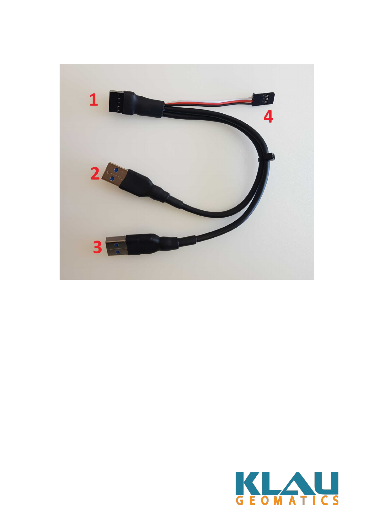
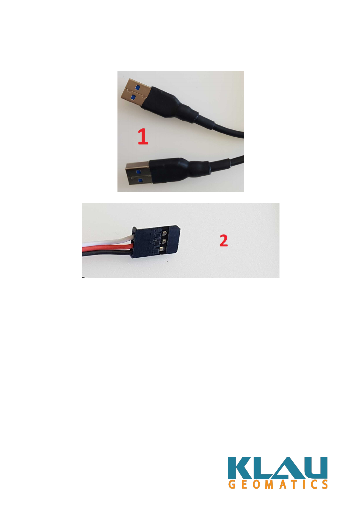
719 Series Wire arness..................................................................................................................6
729 Series PPK................................................................................................................................7
729 Series Wire arness..................................................................................................................8
Antenna............................................................................................................................................9
General Operation..............................................................................................................................10
Technical Specifications – 719 Series................................................................................................11
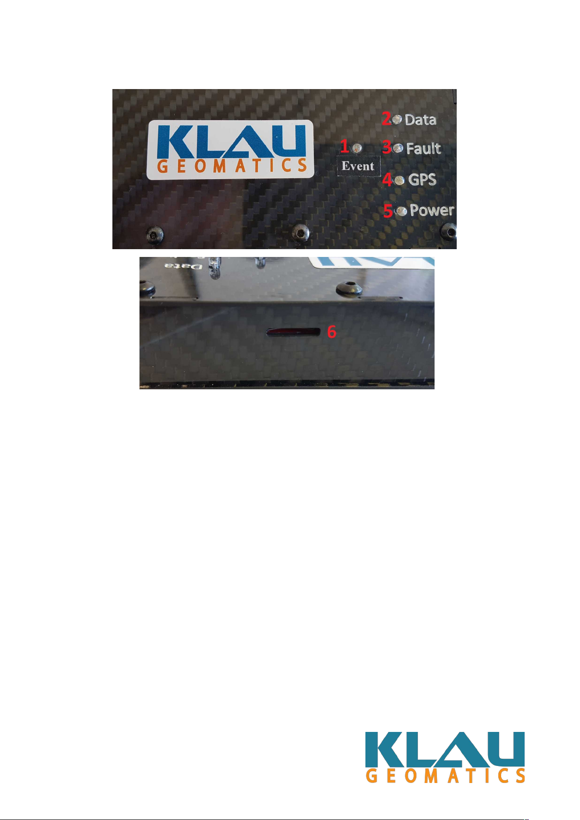
Connections....................................................................................................................................11
Dimensions & Weight....................................................................................................................11
Battery Recommendations.............................................................................................................11
Power Input....................................................................................................................................11
Operating Temperature..................................................................................................................11
Event/Top of Frame Input..............................................................................................................12
Antenna..........................................................................................................................................12
Micro SD Card...............................................................................................................................12
Main Connector.............................................................................................................................13
Technical Specifications – 729 Series................................................................................................14
Connections...................................................................................................................................14
Dimensions & Weight....................................................................................................................14
Battery Recommendations.............................................................................................................14
Power Input....................................................................................................................................14
Operating Temperature..................................................................................................................14
Event/Top of Frame Input..............................................................................................................15
Antenna..........................................................................................................................................15
Micro SD Card...............................................................................................................................15
Warning..............................................................................................................................................16
Rev- 1.00
2